Fab Academy 2015
How to make almost anything

Luis Peña Mendoza

    Assignment 4 - week 4 - Feb 18

    Make the FabISP in-circuit programmer

    Electronics Production

    The task of this week was: Make the FabISP in circuit programmer. I was asked to mill, stuff and program the Fab ISP board, The FabISP is an in-system programmer for AVR microcontrollers, designed for production within a FabLab. This task which allows to program brand new AVR microcontrollers with the desired firmware.

    FAB ISP

    The FAB ISP design we decided to build in the lab is the Neil’s version. The first thing we do is install the Fabmodules, for this we continue the tutorial of Anna Kaziunas

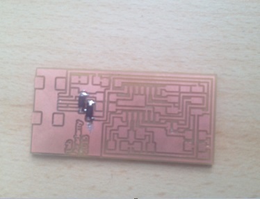
    A. Milling the board

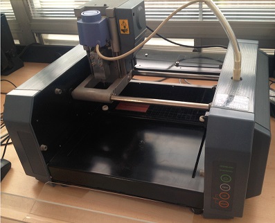
    I milled the board starting from the PNG design available on the class webpage, using the Fab Modules on the lab’s Roland MDX-20 Modela mill. I never used such tool before so took some time to understand its operation, especially regarding the homing and fitting the different milling bits for proper operation. The process was quite straightforward, and the integration with fab modules made it very smooth.
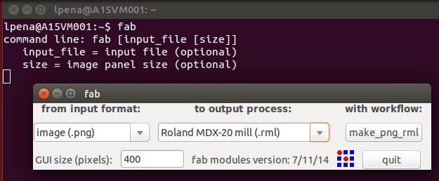
    Once we have installed the Fabmodules, we do the following:

    1. In the terminal of Ubuntu, we write sudo bash for log in as lpena.

    2. I write "fab".

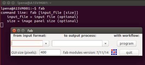
    3. I will get in to the GUI of the Fab Modules.
    4. I select the format and process that we will perform. In this case, Image(.png) and Roland Modela MDX20 mill (.rml).

    5. I click in make_png_rml.
    6. I load the file .png of board.
    7. I select the type of cutter that we will use (1/64) .
    8. I regulate the parameters of milling.

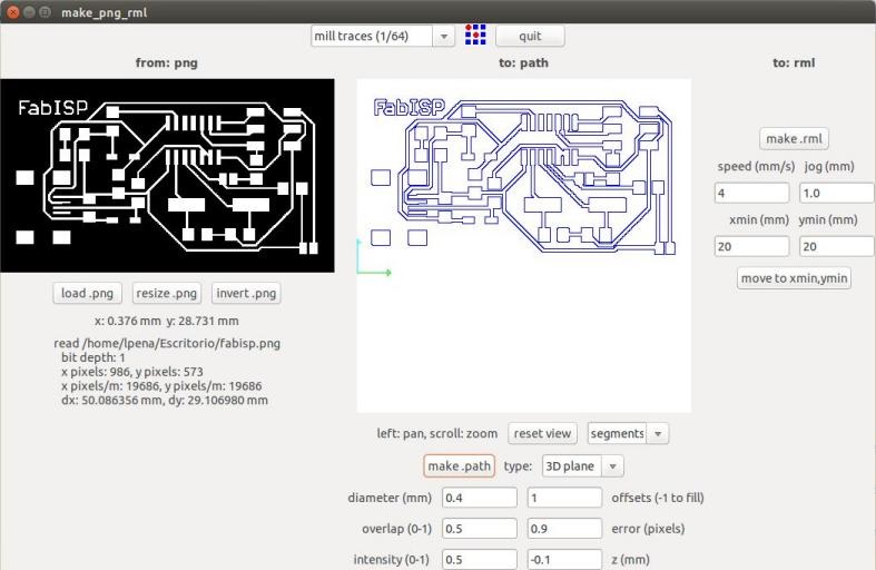
    diameter: 0.4 mm - overlap: 0.5 - offsets: 1 - error: 0.9 pixels - intensity: 0.5 - z: -0.1 mm
    9. I click in make_path, to generate the G-code that will be the file with the trajectories of headstock.
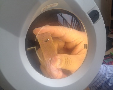
    10. I cleaned up the copper board of impurities (isopropyl alcohol).
    11. I put masking tape on the board in order to attach it in the iron of the Modela MDX20.
    12. I calibrate the origin of the axes X and Y in the milling machine, considering the position of the copper board.
    13. I calibrate the Z-axis, for an optimal milling of the board.
    14. I give you click make.rml

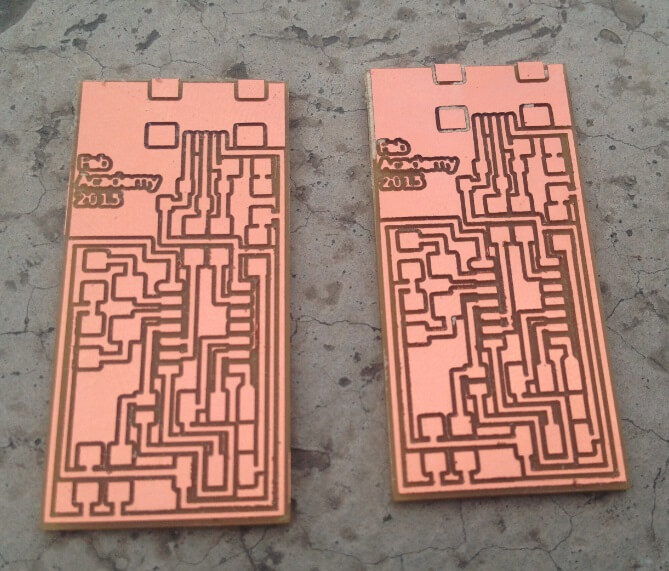
    For milling the traces I used the 1/64’’ inch bit, while for cutting out the board I used the 1/32’’ inch bits. The machine settings I used are:

    • Speed 4, Jog Height 1.0 for milling the traces
    • Speed 2, Jog Height 1.8 for cutting the board

    I experimented with different settings for the jog height, homing the mill in different places of the board to get the lowest possible setting. This finally resulted in a properly milled board. A very interesting fact is that even after several times switching to view mode, and milling attempts the Modela totally respected the homing coordinates, resulting in no displacement of the resulting traces. Cutting out the board took almost the same procedure, and worked quite immediately. This was done by removing the wooden block and putting under the milled board another sheet instead, which made the calibration process much easier thanks to the uniform surface.

    B. Stuffing the FabISP

    Before starting the actual stuffing I took some time to produce a Bill of Materials, matching codes in the schematic with a description and quantity required for each part. This helped me a lot in collecting components from the lab inventory, and will also be useful to track which components are needed to make another similar board in the future. I also managed to salvage the ISP connector from an old board, so I had all material ready. I had already create some boards using through hole parts, but I had never soldered SMD components before, so found it quite intimidating handling such small parts. Even if I followed my instructor advice I found it very difficult to use the magnifying monocular and my glasses at the same time. This led me to much frustration in getting the connection properly soldered and resulted in not very clean component alignment.

    The following is to weld the electronic devices, the bill of material is as follows:

    As a lesson learnt, I will equip my soldering workstation with a magnifying lamp allowing me to solder with glasses on and with more freedom of movement. Repeating this process more times I will propably also get more confident and produce better results. The process took me a couple of hours to complete, mostly because I could not get some of the components to sit cleanly. Another lesson is I should use less solder possible before adding the components to get an easier alignment.

    By testing all the connections to the ATTiny pins I could be more confident while progressing, but later I realized that some of the could be redone in a much cleaner way.


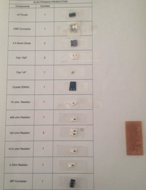
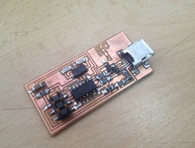
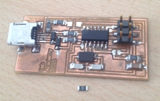
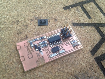
    The welding is according the image below:


    C. Programming the FabISP

    Being my first board I wasn't really sure it would work at first. I downloaded the firmware plus all dependencies and followed the make clean, make program cycle using my instructor FabISP plugged on a second USB port. No error message, so I unsoldered the jumper but my board wouldn't be recognized.

    After several tries, restoring every time the jumper, I couldn't make it work. Then I took a better look at the Makefile. Turned out I needed to uncomment the line invoking avrdude to tell it to use usbtinyisp instead of avrisp.

    AVRDUDE = avrdude -c usbtiny -p $(DEVICE) # edit this line for your programmer
    			# AVRDUDE = avrdude -c avrisp2 -P usb -p $(DEVICE) # edit this line for your programmer

    The process this time was successful, my ISP was recognized by OSX, and it also worked for programming one of my collegues board.


    The next was programming the board.
    For programming we do the following:

    1. Connect Avr Programmer with FabISP. If the led glows green on the programmer, then we can proceed to the next step, if we do not recheck the solder.

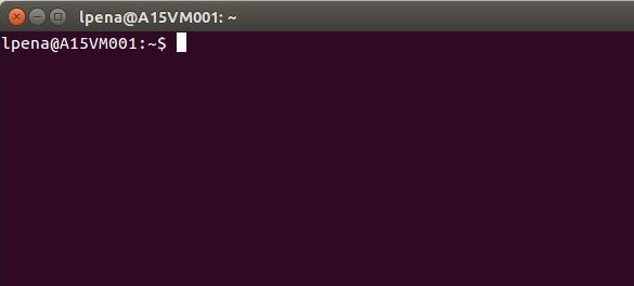
    2. Copy the next syntax in the terminal of Ubuntu as root.

    sudo apt-get install flex byacc bison gcc libusb-dev avrdude 
    sudo apt-get install gcc-avr 
    sudo apt-get install avr-libc 
    sudo apt-get install libc6-dev 
    

    Firmware.
    4. Program the Fab ISP copying the next code inside Firmware folder.

    make clean 
    make hex
    sudo make fuse
    sudo make program


    					avrdude -c avrisp2 -P usb -p attiny44 -U flash:w:main.hex:i
    
    avrdude: AVR device initialized and ready to accept instructions
    
    Reading | ################################################## | 100% 0.01s
    
    avrdude: Device signature = 0x1e9207
    avrdude: NOTE: FLASH memory has been specified, an erase cycle will be performed
    To disable this feature, specify the -D option.
    avrdude: erasing chip
    avrdude: reading input file “main.hex”
    avrdude: writing flash (2020 bytes):
    
    Writing | ################################################## | 100% 0.70s
    
    avrdude: 2020 bytes of flash written
    avrdude: verifying flash memory against main.hex:
    avrdude: load data flash data from input file main.hex:
    avrdude: input file main.hex contains 2020 bytes
    avrdude: reading on-chip flash data:
    
    Reading | ################################################## | 100% 0.59s
    
    avrdude: verifying …
    avrdude: 2020 bytes of flash verified
    
    avrdude: safemode: Fuses OK
    
    avrdude done. Thank you.
    
    avrdude -c avrisp2 -P usb -p attiny44 -U hfuse:w:0xDF:m -U lfuse:w:0xFF:m
    
    avrdude: AVR device initialized and ready to accept instructions
    
    Reading | ################################################## | 100% 0.01s
    
    avrdude: Device signature = 0x1e9207
    
    avrdude: reading input file “0xDF”
    avrdude: writing hfuse (1 bytes):
    
    Writing | ################################################## | 100% 0.00s
    
    avrdude: 1 bytes of hfuse written
    avrdude: verifying hfuse memory against 0xDF:
    avrdude: load data hfuse data from input file 0xDF:
    avrdude: input file 0xDF contains 1 bytes
    avrdude: reading on-chip hfuse data:
    
    Reading | ################################################## | 100% 0.00s
    
    avrdude: verifying …
    avrdude: 1 bytes of hfuse verified
    avrdude: reading input file “0xFF”
    avrdude: writing lfuse (1 bytes):
    
    Writing | ################################################## | 100% 0.00s
    
    avrdude: 1 bytes of lfuse written
    avrdude: verifying lfuse memory against 0xFF:
    avrdude: load data lfuse data from input file 0xFF:
    avrdude: input file 0xFF contains 1 bytes
    avrdude: reading on-chip lfuse data:
    
    Reading | ################################################## | 100% 0.00s
    
    avrdude: verifying …
    avrdude: 1 bytes of lfuse verified
    
    avrdude: safemode: Fuses OK
    
    avrdude done. Thank you.


    5. For verify that the computer is recognizing the device, type:

    lsusb
    

    6. Desolder jumpers.

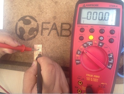
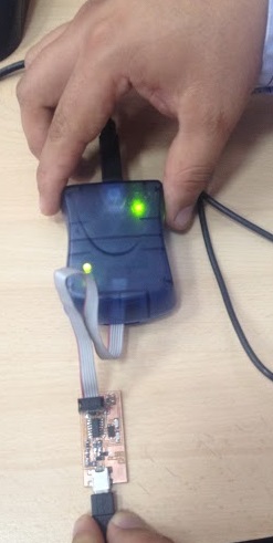
    7. Make IDC ISP cable.
    8. Congratulations, your FabISP is ready!

    D. Conclusion

    I enjoyed much this week assignment. Being able to create from scratch a working board and programming it made the process very rewarding.
    Is recomedable use a table of sacrifice to protect the machine.
    To weld we have to be careful not to heat up too the integrated and avoid the lift of the tracks.
    Another recommendation is to see the orientation of the diodes and the Attiny44a.
    For weld repair, as best we can do is help us with a magnifying glass, paste to weld and a multimeter to detect errors. By placing a point of tin and then warming up the area with the soldering iron to weld the piece.
    We recommend using solder remover to remove excess solder