Assignment 3 - week 3 - 11/02
| Design, make, and document a press fit construction kit |
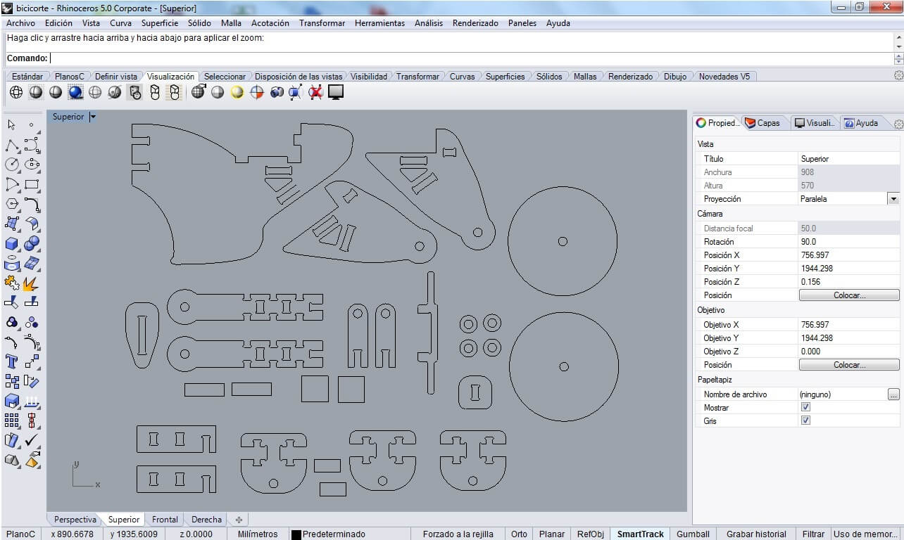
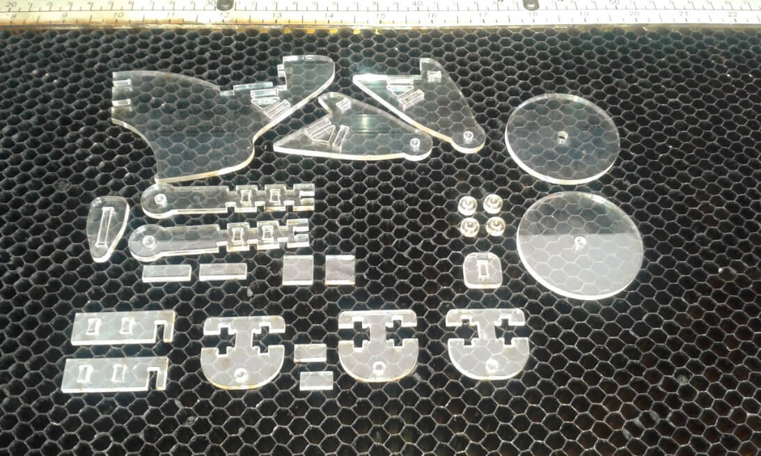
The major issues I found are related to my choice of using press-fit joint with an horizontal design for acrylic
A.5 Acrylic for the mototcycle kit
Using this design with acrylic has proven to be a challenge.
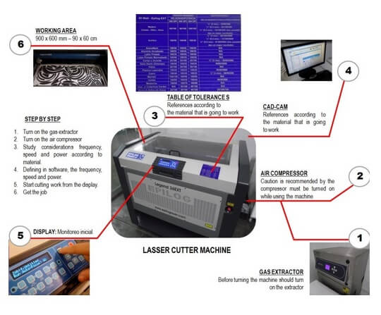
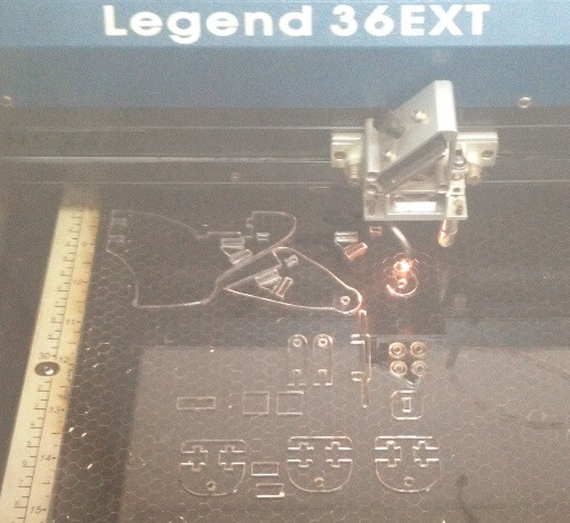
For the acrylic we have used the following parameters on the Epilog Laser Cut - Legend 36EX
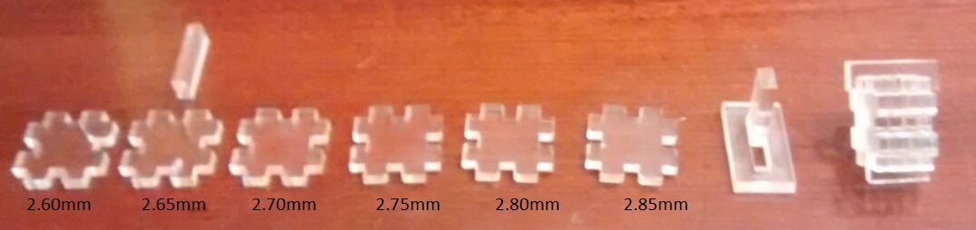
The material is very irregular each test needs to be repeated many times, especially for the configuration of cutting power. In my first tests with acrylic with a speed:14%, power:100% and frecuency:5000 Hz, the cutting of material was not complete, I changed the speed:9%, power:100% and frecuency:5000 Hz, this setting was better.
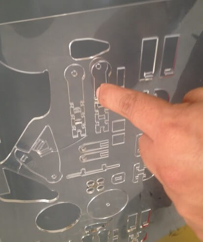
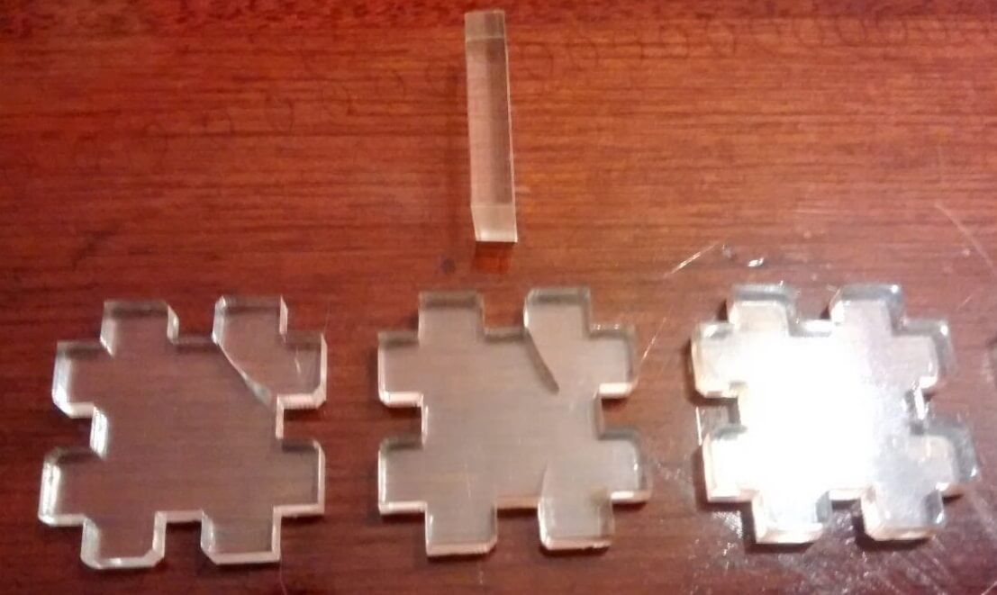
The complete motorcycle, not totally cut
A.6 Results achieved and lessons learnt
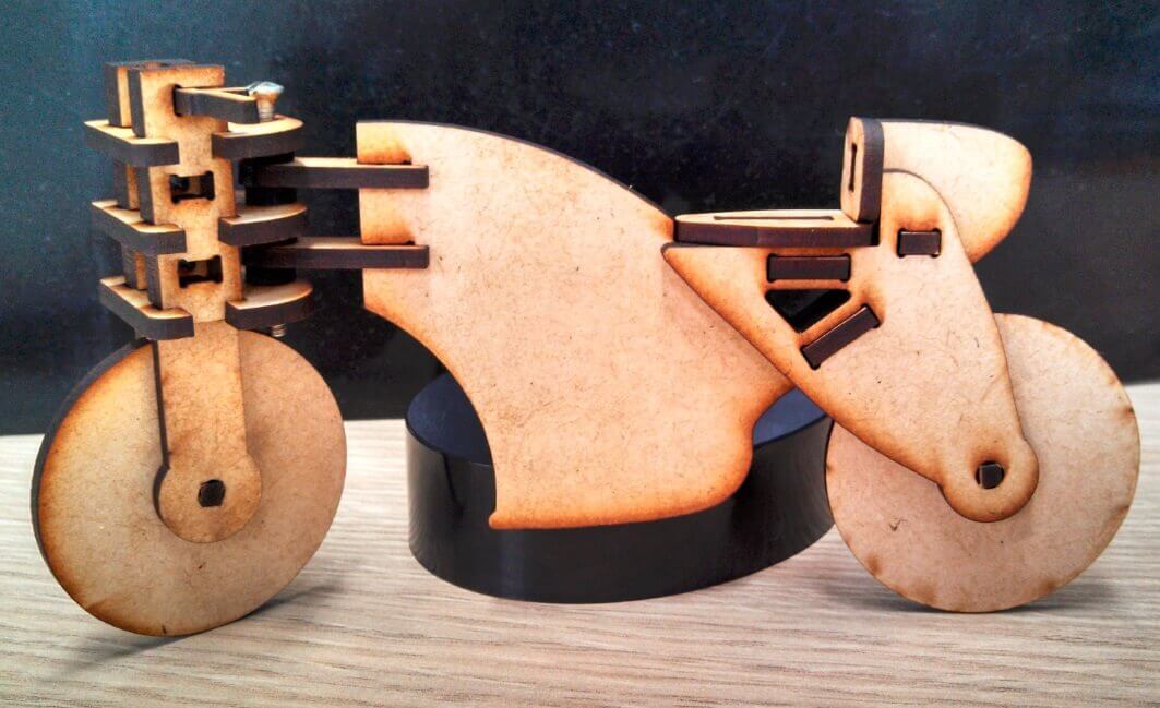
I am satisfied with the overall results of the tool. The following picture shows the final result.
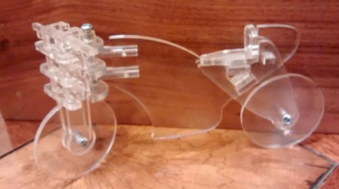
Motorcycle assembled
I felt my design would be better suited for other kind of lasercut material such as mdf.
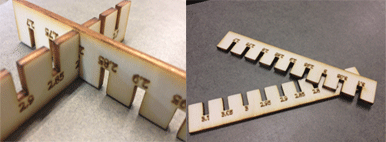
I followed the same process I used for mdf. Having a bit more experience I immediately started with several tests for the laser power and speed, creating a small test board with parameters in it, till I found the right settings.
Finally I was able to assemble the motorcycle in mdf using the new pieces. The fit was much more solid than the equivalent made in acrylic.
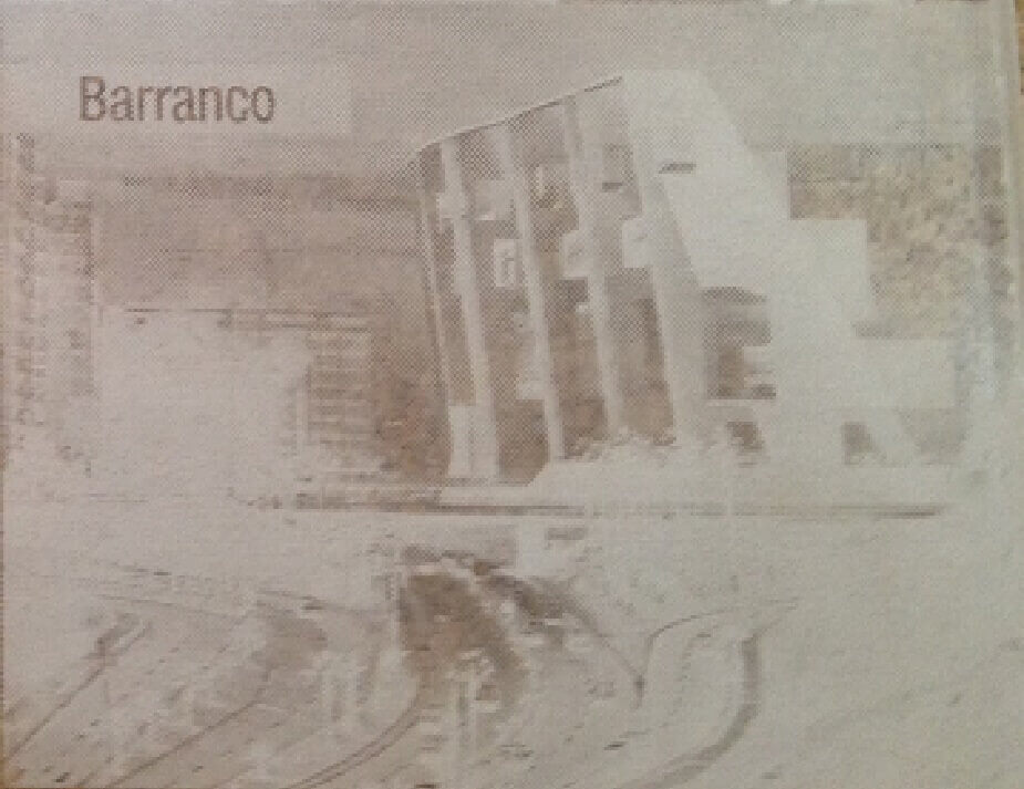
Also I experienced whith raster process in acrylic, as shown in figure following:
A.7 Conclusion
I liked the simplicity and immediate results Offering laser cutter available in the Tecsup Fab Lab. The use of the machine is very simple, the key element is the setting should be done before the final cut
It is highly recommended to start working with the test material before the preparation of the design, you can save time if work is done in this order .
Differences observed Between work in acrylic and mdf Were:
1. mdf absorbs moisture because it is made from wood, this material is hygroscopic, in press fit joints can be skipped when the material swells.
2. Both the acrylic as MDF show variability in the thickness of the plates and even within a single plate variability also exists.
3. The model turned me mdf more stable than the model in acrylic.
4. For constructions using MDF press fit could use a lower tolerance because this material is flexible and allows a better fits, however with acrylic this is not possible as this material is broken.
B. Second Part: Making vynil cut stancils
B.1 Desing and cut of the stancils
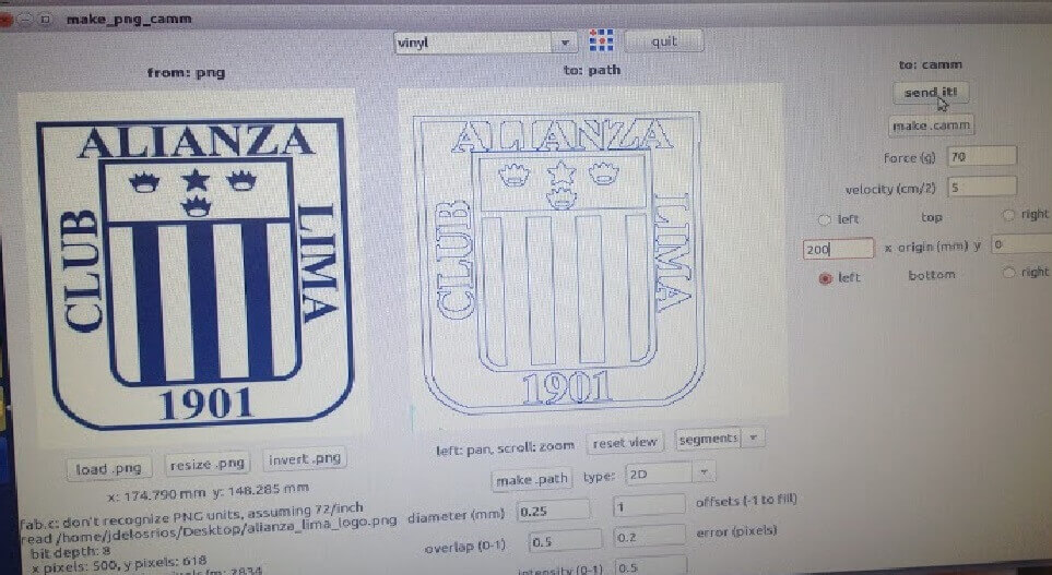
During the week l used the laser cutter, but luckily found some time also to explore the possibilities given by the vynil cutter. I managed to find a small logo of my favourite football team in Peru: Alianza Lima and created some stickers for my library.The stickers where created starting from JPG files, but they were converted into PNG files for processing, using PNG files with the fab modules.
First sticker with small typeface
I initially tried to add to the sticker some text in a quite small typeface. This made the whole process really difficult, because letters were too small to stick well and the fill of some letters required some patience to be separated by the transfer tape. I eventually managed to transfer it on a piece of paper , but had to relocate some smaller elements practically by hand.
As a second try and using bigger letters, I cut again a similar logo, this time the process was very smooth, and I easily managed to transfer the logo on a piece of paper with the transfer material, as shown in the picture.
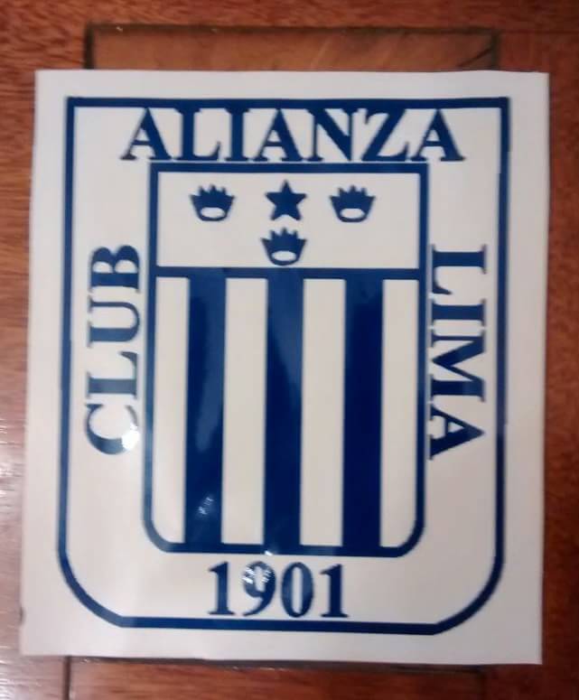
First sticker with small typeface
Downloading link for my archives:
Archives
B.2 Conclusion
I really liked the simplicity and immediate results offered by the large vynil cutter available in the Tecsup Fab Lab, much more advanced than the small A4 cutter I had used previously. The ability to cut in different parts of the material and to exactly know the area available for cutting allowed me to reuse the same vynil for several tests.
Also the possibility to use the transfer sheet for moving the stickers from one surface to another is a great improvement from my previous workflow.
C. Third Part: Additional Research
I researched about other technologies also available for cutting
I show a list of references about other technologies:
- Waterjet: A water jet cutter, also known as a water jet or waterjet, is an industrial tool capable of cutting a wide variety of materials using a very high-pressure jet of water, or a mixture of water and an abrasive substance. The term abrasivejet refers specifically to the use of a mixture of water and abrasive to cut hard materials such as metal or granite, while the terms pure waterjet and water-only cutting refer to waterjet cutting without the use of added abrasives, often used for softer materials such as wood or rubber.Waterjet cutting is often used during fabrication of machine parts. It is the preferred method when the materials being cut are sensitive to the high temperatures generated by other methods. Waterjet cutting is used in various industries, including mining and aerospace, for cutting, shaping, and reaming.
- Wire EDM: Electric discharge machining (EDM), sometimes colloquially also referred to as spark machining, spark eroding, burning, die sinking, wire burning or wire erosion, is a manufacturing process whereby a desired shape is obtained using electrical discharges (sparks). Material is removed from the workpiece by a series of rapidly recurring current discharges between two electrodes, separated by a dielectric liquid and subject to an electric voltage. One of the electrodes is called the tool-electrode, or simply the "tool" or "electrode", while the other is called the workpiece-electrode, or "workpiece".When the distance between the two electrodes is reduced, the intensity of the electric field in the volume between the electrodes becomes greater than the strength of the dielectric (at least in some point(s)), which breaks, allowing current to flow between the two electrodes. This phenomenon is the same as the breakdown of a capacitor (condenser) (see also breakdown voltage). As a result, material is removed from both electrodes. Once the current stops (or is stopped, depending on the type of generator), new liquid dielectric is usually conveyed into the inter-electrode volume, enabling the solid particles (debris) to be carried away and the insulating properties of the dielectric to be restored. Adding new liquid dielectric in the inter-electrode volume is commonly referred to as "flushing". Also, after a current flow, the difference of potential between the electrodes is restored to what it was before the breakdown, so that a new liquid dielectric breakdown can occur.
- Hot Wire: A hot-wire foam cutter is a tool used to cut polystyrene foam and similar materials. The device consists of a thin, taut metal wire, often made of nichrome or stainless steel, or a thicker wire preformed into a desired shape, which is heated via electrical resistance to approximately 200°C. As the wire is passed through the material to be cut, the heat from the wire vaporises the material just in advance of contact.The depth of the cut is limited only by the wire length. Width of cut is limited by throat, if any.