Assignment 2 - week 2 - 04/02

    Model (draw, render, animate, simulate,....) a possible final project and post it in your class page

    Computer Aided Design

    The Assignment for this week was to try different design softwares.

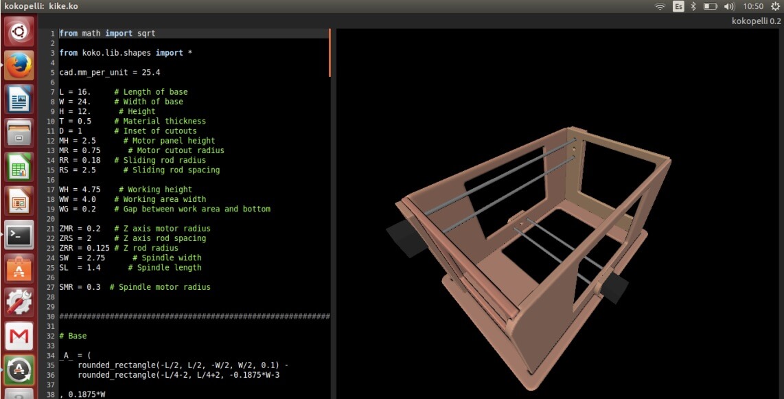
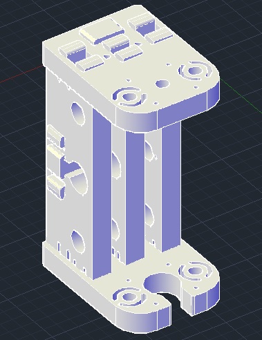
    A. Generative Design

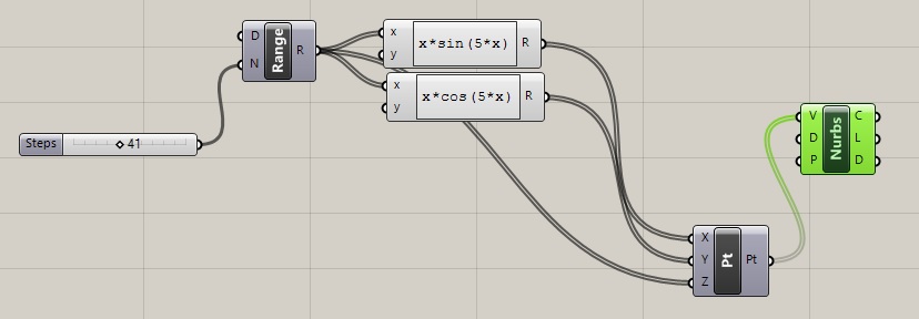
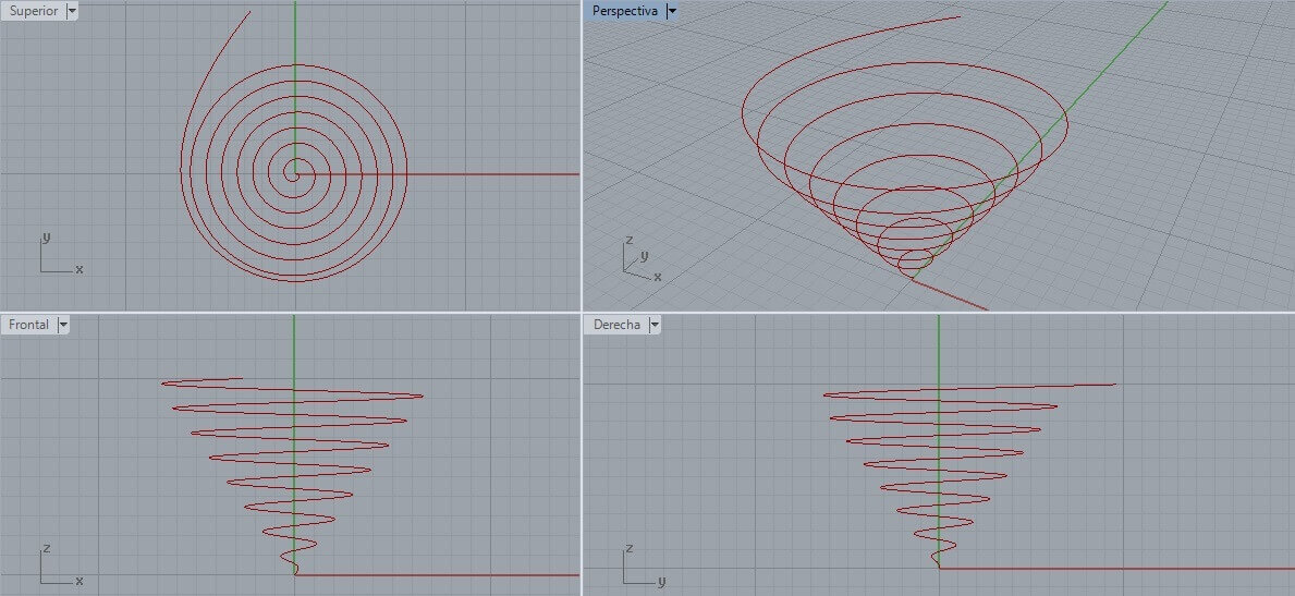
    Design method of creating models and animations from algorithms or sets of rules by using programming languages such as Processing for example,It is based on parametric modeling. It is a fast method of exploring design possibilities that is used in various design fields such as art, architecture, communication design, and product design.


    a.1. Processing

    The first software of generative design I used was processing , this is an programming language open source, Processing is based on Java, but because program elements in Processing are fairly simple, I learnt to use it even although I didn't know about Java. The first software of generative designg I used was processing , this is an open source programming language and integrated development environment (IDE) built for the electronic arts, new media art, and visual design communities with the purpose of teaching the fundamentals of computer programming in a visual context, and to serve as the foundation for electronic sketchbooks. The project was initiated in 2001 by Casey Reas and Benjamin Fry, both formerly of the Aesthetics and Computation Group at the MIT Media Lab. One of the stated aims of Processing is to act as a tool to get non-programmers started with programming, through the instant gratification of visual feedback. Processing is based on Java, but because program elements in Processing are fairly simple, I learnt to use it even although I didn't know about Java. I decided to create my own program to generate a fractal (an irregular geometric object with an infinite nesting of structure at all scales) in Processing.

    int max_left_deep = 12, max_right_deep = 12, max_deep = 12;
    					color bc = color( 160, 82, 45 );
    					color ec = color( 0, 255, 0 );
    					int prod = 60; 
    					int branchLeft = 100, branchRight = 100;
    					int deep = 0;
    					float angL = PI/5, angR = PI/4;
    					 
    					void setup() {
    					size( 800, 600 );
    					strokeWeight( 6 );
    					frameRate( 1 );
    					background(255); 
    					}
    					 
    					void keyPressed() {
    					switch( key ) {
    					case 'q': branchLeft += 5; break;
    					case 'a': branchLeft -= 5; break;
    					case 'w': branchRight += 5; break;
    					case 's': branchRight -= 5; break;
    					     
    					}
    					 
    					branchLeft = constrain( branchLeft, 5, 100 );
    					branchRight = constrain( branchRight, 5, 100 );
    					}
    					 
    					void draw() {
    					background( 255 );
    					float tl =map( random(150), 0, width, 0, PI ), tr =map( random(150), 0, height, 0, PI );
    					angL += (tl - angL)/5;
    					angR += (tr - angR)/5;
    					 
    					 
    					float grL = map( angL, 0, PI, 0, 180 ), grR = map( angR, 0, PI, 0, 180 );
    					draw_branch( width / 2, height - 100, -HALF_PI, 1.0 );
    
    					}
    					 
    
    					void draw_part() {
    					stroke( color(
    					map( deep, 0, max_deep, red(bc), red(ec) ),
    					map( deep, 0, max_deep, green(bc), green(ec) ),
    					map( deep, 0, max_deep, blue(bc), blue(ec) )
    					) );   
    
    					line( 0, 0, 100, 0 );
    					}
    					 
    					void draw_branch( int originX, int originY, float ang, float scal ) {
    					deep++;
    					 
    					pushMatrix();
    					translate( originX, originY );
    					rotate( ang );
    					scale( scal );
    					 
    					draw_part();
    					 
    					if ( deep < max_left_deep )
    					draw_branch( branchLeft, 0, -angL, 0.8 );


    					translate( 100, 0 );
    					scale( 0.8 );
    					rotate( PI / 12 );
    					draw_part();
    					if ( deep < max_right_deep )
    					draw_branch( branchRight, 0, angR, 0.8 );
    					translate( 100, 0 );
    					rotate( -PI / 12 );
    					scale( 0.8 );
    
    					if ( deep == max_deep-1 && random( 100 ) < prod ) { 
    					noStroke();
    					fill( #FFA500 );
    					ellipse( 100, 0, 100, 100 );
    					}
    					 
    					popMatrix();
    					deep--;
    					}
    					

    B. Parametric Design

    Parametric design uses parameters to define a model (dimensions, for example). Examples of parameters are: dimensions used to create model features, material density, formulas to describe swept features, imported data (that describe a reference surface, for example). The parameter may be modified later, and the model will update to reflect the modification. Typically, there is a relationship between parts, assemblies, and drawings. A part consists of multiple features, and an assembly consists of multiple parts. Drawings can be made from either parts or assemblies. Example: A shaft is created by extruding a circle 100 mm. A hub is assembled to the end of the shaft. Later, the shaft is modified to be 200 mm long (click on the shaft, select the length dimension, modify to 200). When the model is updated the shaft will be 200 mm long, the hub will relocate to the end of the shaft to which it was assembled, and the engineering drawings and mass properties will reflect all changes automatically.


    b.1 Rhinoceros and Grasshopper
    The next software I used was Rhinoceros, which is a licensed software, it is designed to model products, furniture, structures and complex geometric systems via Grasshopper. Rhinoceros is based on NURBS tecnology (non-uniform rational B-spline), which is a mathematical model based on Pierre Bézier´s theory to generate curves and surfaces. This makes it very popular in graph computation.
    Grasshopper is a Rhinoceros plug in that allows us to create models by using graph programming (nodes via). It is oriented towards generative designs.


    b.3 Autodesk Inventor
    Autodesk Inventor is a parametric software. This is 3D mechanical CAD software for creating 3D digital prototypes used in the design, visualization and simulation of products.

    The following is an example I used Inventor to design same part of my project.


    Downloading link for the program:
    Inventor

    Downloading link for my archives:
    Archives


    b.4 123D Make
    From the family of the 123D Autodesk software, this tool helps us to obtain different types of models from a file in 3D. The reason I chose it because I wanted to experiment with the technique Waffle. 123D Make comes with the option "Interlocked Slices". Sometimes it is necessary to adjust the thickness values of each section or regulate dimensions to avoid errors.

    The following is an example of what can be done from a human head.

    Downloading link for the program:
    123D Make

    Downloading link for my archives:
    Archives


    b.5 Kokopelli
    Kokopelli is parametric, comparative, implicit frameworks for computer-aided design that grew at the Center for Bits and Atoms – – and was tested in the Fab Academy. At the moment, kokopelli is suitable for 2D and 3D modeling (and some even use it for PCB design!). It can export .pngs, .svgs, and .stls, and there’s basic built-in CAM for 2-, 3-, and 5-axis subtractive machining.

    The following is an example I used Kokopelli to design the structure of my project from code

    Downloading link for the program:
    Kokopelli


    Downloading link for my archives:
    Archives


    C. Final Project

    I have worked previously with AutoCAD to modeling parts , but working with Inventor , Solidworks and Rhino were not too complicated . For my final project I decided to use AutoCAD to model the structure of my project because I have more experience in the use of this software. I drawed piece by piece of my final project then I assembled the pieces to form components or sub systems. I used the GrabCAD sofware- a library for solids - to download bearing 3ds , the servomotors , etc. The collet cone is based on the BT30 model (0.5 scale) I downloaded from: www.tools-n-gizmos.com . The system of automatic tool changer model is based in a component made of the Archlab of the University of Navarra.


    To render and to simulate I decided to use AutoCAD is very easy to perform this operation in this software


    Downloading link for my archives:
    Archives