Fab Academy 2015
How to make almost anything

Luis Peña Mendoza

    Assignment 16 - week 16 - May 13

    Propose a final project that integrates the range of units covered:

    what will it do?

    who's done what beforehand?

    what materials and components will be required?

    where will they come from?

    how much will it cost?

    what parts and systems will be made?

    what processes will be used?

    what tasks need to be completed?

    what questions need to be answered?

    what is the schedule?

    how will it be evaluated?

    projects can be separate or joint, but need to show individual mastery of all of the skills where possible, you should make rather than buy the parts of your project

    Applications and Implications

    What will it do?

    The project was to develop a CNC milling machine for PCB plates, which mill has the capacity to double-layer plates and a system of automatic exchange of tools. One of the main problems when designing an electronic board is the distribution of the components and routing their paths, this is easily solved by designing a double sided PCB. However in this process both sides must be aligned, otherwise the holes and vias in each layer won't match this usually happens when turning the boards manually. I decided to build a machine that can make double side PCB boards easier, as current machines usually finish one side of the board first and then the user swaps the board side being careful to keep the pcb same location. My project seek to reduce or even eliminate the time spent changing the side of the board.

    Who's done what beforehand?

    A list of references where I take some of my inspirations to make this experiment and for further research:

    1. Patrick Thorn - MDX40A Rotary Axis
    2. Mikey Sklar - Double Sided PCB CNC Milling
    3. FlatCAM
        http://flatcam.org/manual/procedures.html#side-pcb

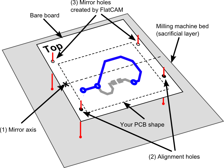
        The main idea behind this process is to ensure that when you turn your board around to mill the bottom side of your PCB it will be perfectly aligned with the top side.The alignment is accomplished by using alignment holes/pins. These are holes on your board and on the milling machine bed (typically a board made of wood, known as “sacrificial” layer). The pins are used to align the holes on the board to the holes on the sacrificial layer. The holes are always symmetrical across a mirror axis. This ensures that when you turn your board around, the board can be aligned using the same alignment holes as before.

    4. HungSic Jang - Homemade CNC ATC Test Automatic Tool Changer

What materials and components will be required?

Initially for this phase of the prototype, it requires the following
  • Micro Environment materials
    • Wood, Plastic, Acrylics, 3D print board cases,
  • Other Components:
    • Power Source, RGB Leds, Electrical filaments, Electronic components
    • Sensors
      • Software:
        • OpenCV (Open Source Computer Vision), Processing for local testing and rapid prototyping


      • Where will they come from?

        The majority are laboratory materials, except the sheet of extruded acrylic, bolts, nuts, threaded rods, and servo motors.
        The mechanical components I bought are from the Malvinas shopping center in the center of Lima.
        The servo motors I bought in ideasmultiples labs, importing company in Lima.
        What processes will be used?

        To obtain the case and part of the mechanical, I used the process of mechanical design and modeling with CAD software, in addition to the cutting process on the shopbot machine.
        To make the control plate, use the process of schematic design and routing of the board, in addition to the milling process of the copper plate.