


Output Devices
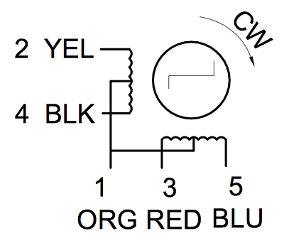
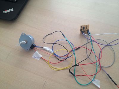
This week assignment was to make some output devices. For this assignment I will need to move up and down a single elements with a step motor. To drive a motor I need to create a board with a controller (Attiny44a) and MOSFETs. The metal–oxide–semiconductor field-effect transistor practically is a switch that can be driven by applying a voltage to one of its three pins (called gate). Each MOSFET has a Gate, a source and a drain (flange). If there is not positive voltage applied between the gate and the source the MOSFET is not conducting. The stepper motor consist of a stator an a rotor. The rotor carries a set of permanent magnets, and the stator has the coils. There are four coils (90 angle between each other) and they are activated in a ciclic order. It divides a full rotation into a number of equal steps and we can control the position (move and hold) of these steps without any feedback sensor. There are different driving modes: Wave drive (only one coil is energized each time), Full step drive (the coils are energized in pairs so the motor will need double of the voltage), Half Stepping (all coil pairs can be energized simultaneously, causing the rotor to rotate half the way as a normal step), microstepping (power the coils with a waveform, in this way, the positioning from one step to the other is smoother). For my assignment I will use an unipolar stepper motor. It has 6 wires (four for the out pin and two for the power input). It moves at 7.5 degrees/step with one step at time and it draws 500mA. I will need to calcolate the speed and movement (up / down) based on the diameter of my gear. 360/7.5 gives me 48 steps every revolution. If I use a gear of 1" diameter (2.54 cm) I will have 2.54 cm*pi/2)= 3.98 cm per revolution....too much. I am going to create a smaller model so I think I will use the gear on the motor. 1/4"*2.54 * pi/2= 0.99cm per revolution.
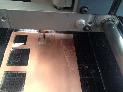
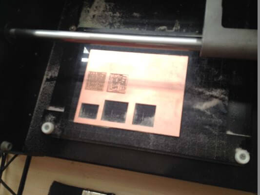
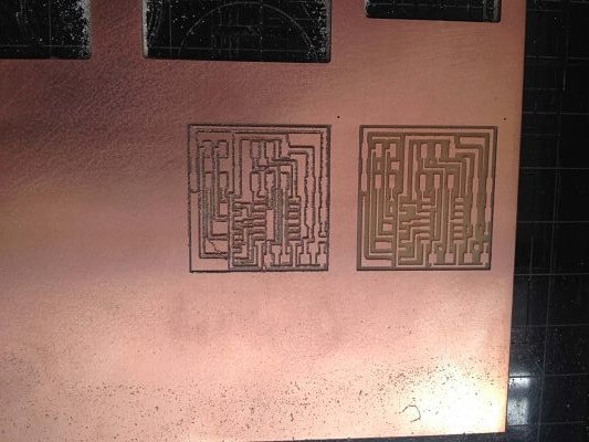
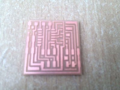
A. Manufacturing the board
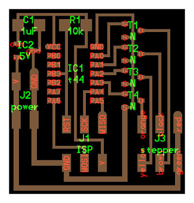
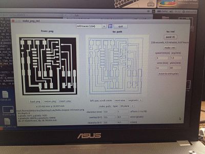
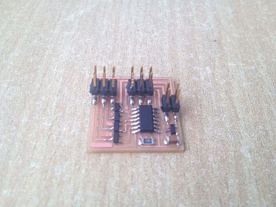
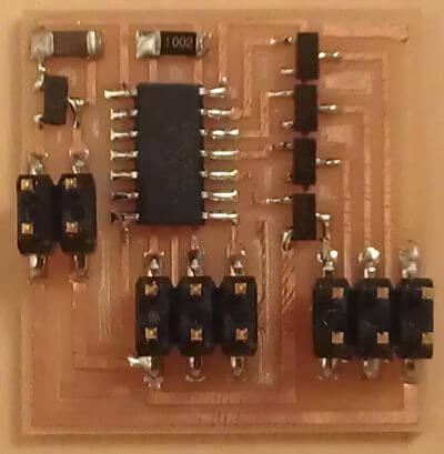
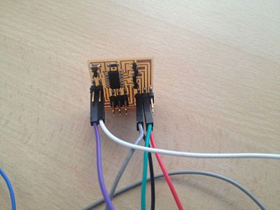
: For manufacturing I used the Roland modeled MDX20, double-sided tape, isopropyl alcohol and a copper plate. Bill of material: Stepper - 1 microcontroller AtTiny44 - 1 Fab ISP conector - 1 conector for stepper - 1 capacitor 1UF - 1 resistors of 10k Ω - 4 Mosfet 355 Channel N - 1 power conector - 1 voltage regulator 5V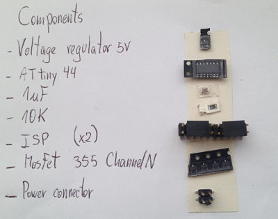
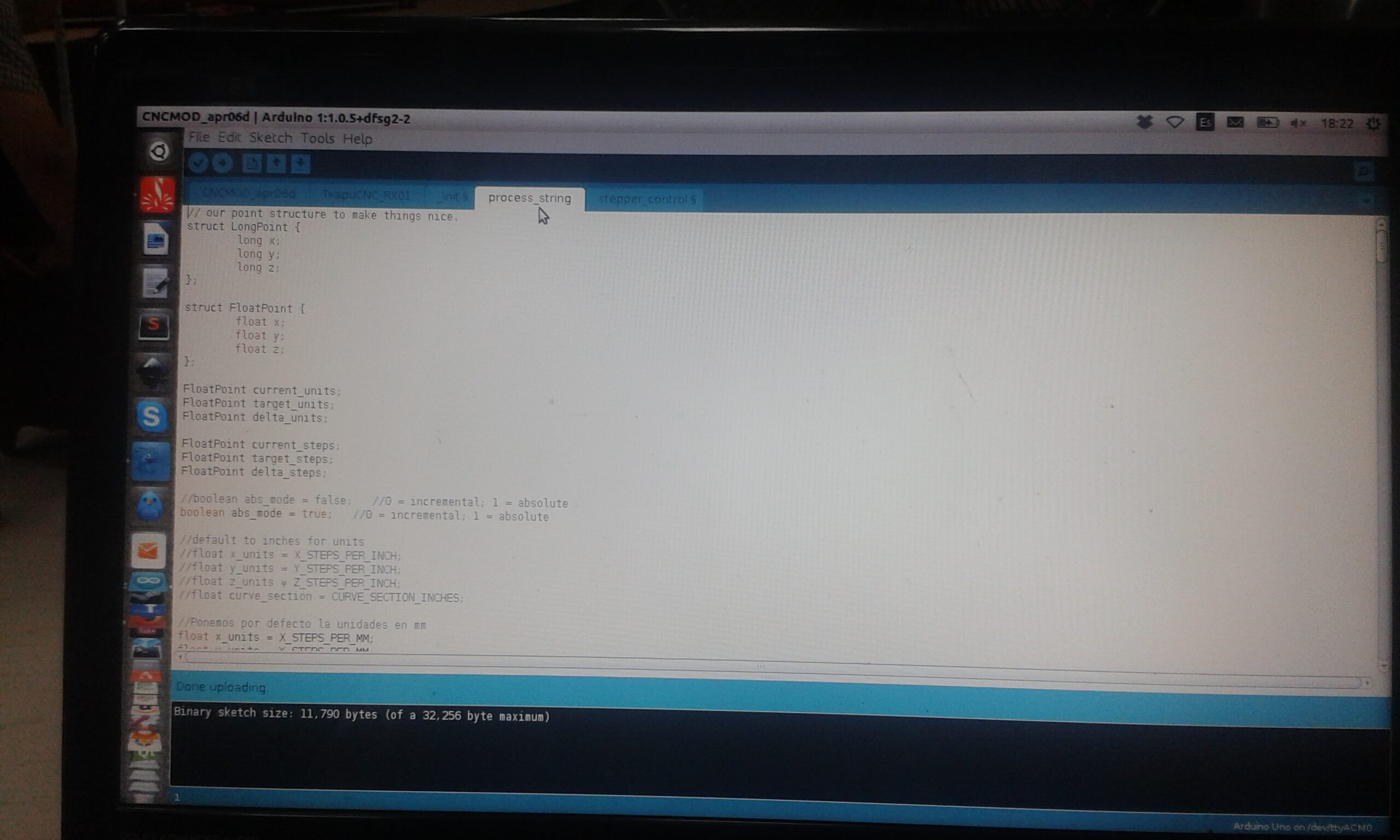
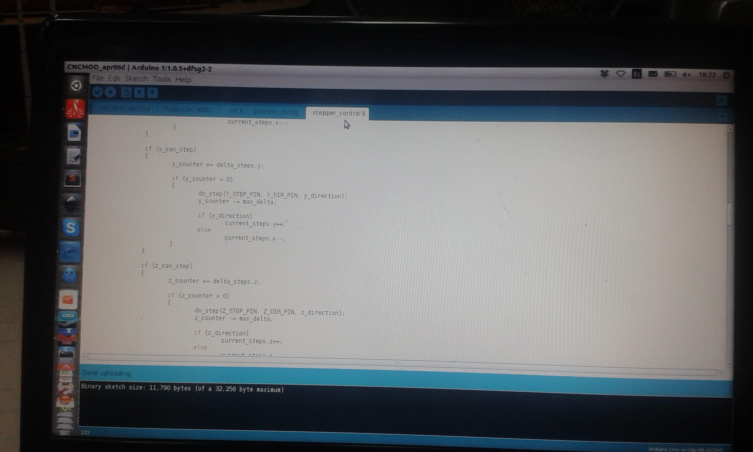
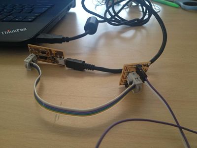
A. Programming the board
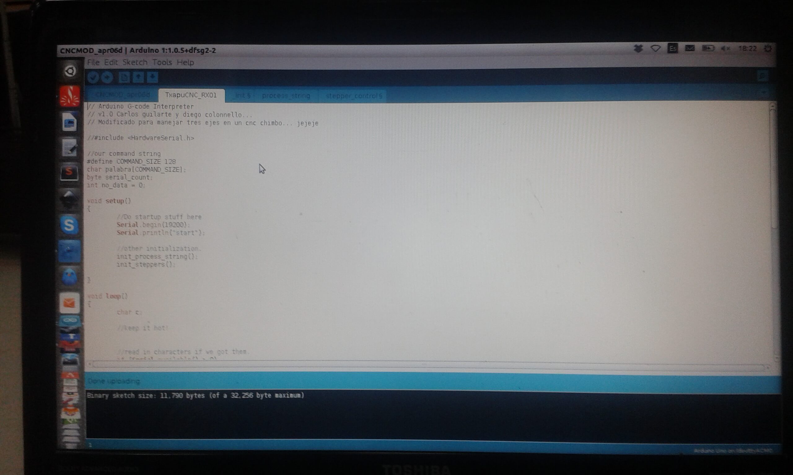
For programming the board you need the C and makefiles, you can grab them from this week class web, download them and put the files in a folder anywhere on your hard drive. Then open a terminal window and change directory "cd" to the folder where you save the files from before. Once there plug both FAB ISP (check for corresponding black wire with GND pin and red with VCC pin, otherwise you can get your board fried) and in the terminal execute the following commands: To schedule our sensors, we are going to take as example the temperature sensor. What we do is to enter the page: http://academy.cba.mit.edu/classes/input_devices/index.html And we download the files .c and "make" Then we opened the console of UBUNTU and we going to the folder where we have the files.
We write in the console: sudo make -f hello.stepper.44.full.make program-usbtiny.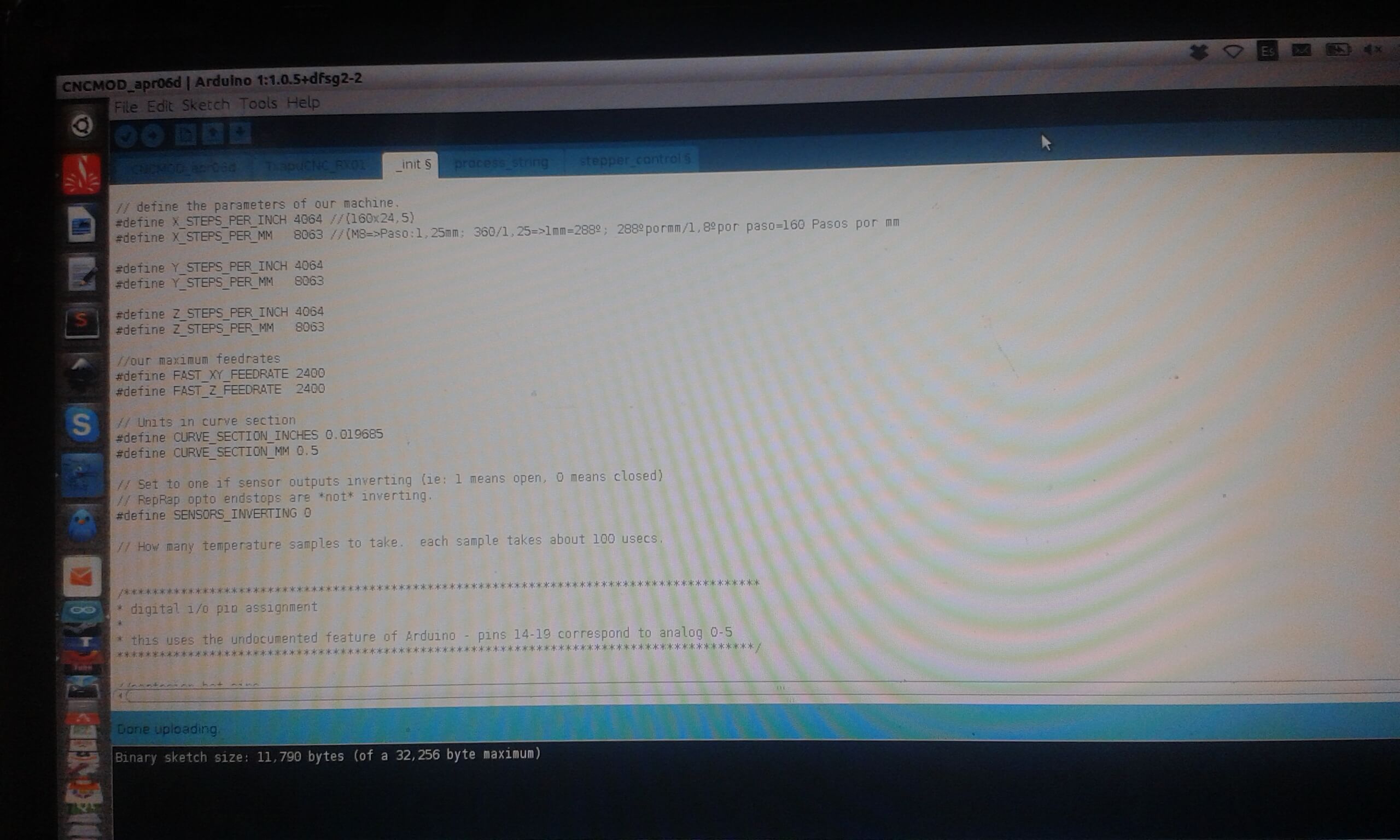
Downloading link for my archives: Archives