

Input Devices
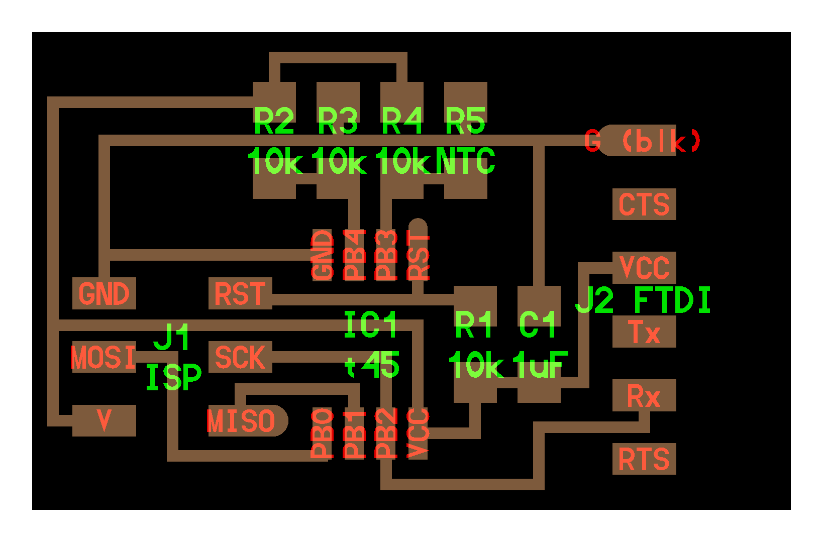
This week assignment was to make some input devices. An input device provides information about a work environment, this information is sensed by a device called sensor and then is processed and measured by a microcontroller. Some sensors like the thermistor measures temperature, hall effect sensors measure the magnetic field or simply buttons that sense the state on a microcontrollers input. For the assignment I fabbricated one of Neil's input devices: temperature.
A. Manufacturing the board
: For manufacturing I used the Roland modeled MDX20, double-sided tape, isopropyl alcohol and a copper plate. Modela machining parameters First, we entered the FabModules, and select make_png_rml and follow the steps. Step 1. We select the top MILL TRACES (1/64) This first step is important because otherwise we can not cut anything, or we err by making the stroke of the tracks. Step 2. Load the image with the Load.png button and verify the size or our board dx and dy in millimeters. We verified that the image which is going to make tracks. Step 3. We MAKE.PATH click, and select segments, so we'll see traces of milling. We enter the parameters of diameter (0.4) mm, overlap (0.5), intensity (0.5), offsets (1), error (0.9), z (-0.1) mm. And select Make.Path to update the changes. We must verify that no crosses on the slopes, otherwise we have to modify the design. Step 4. We place 1/64 milling tool and move to the point of origin (xmin, ymin) where engraving will. Step 5. seteamos the z until this next to the board. Step 6. Make.rml and Send.it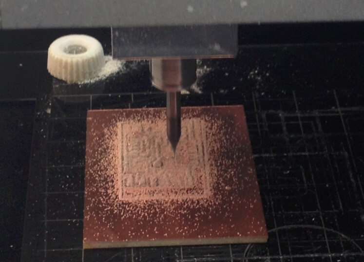
A. Programming the board
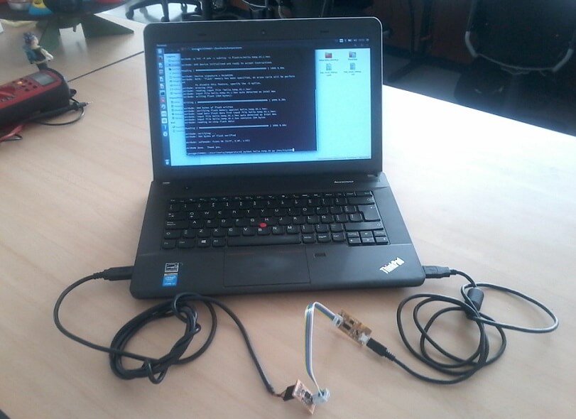
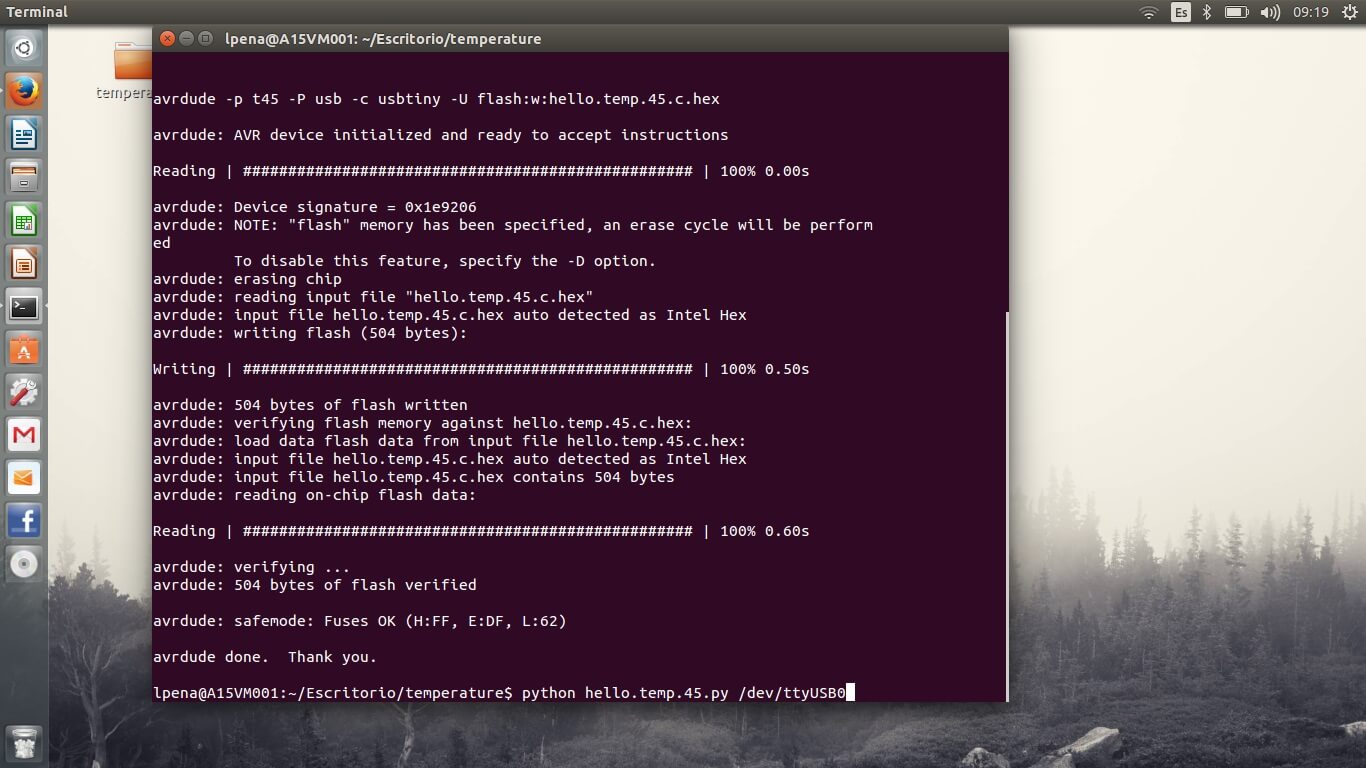
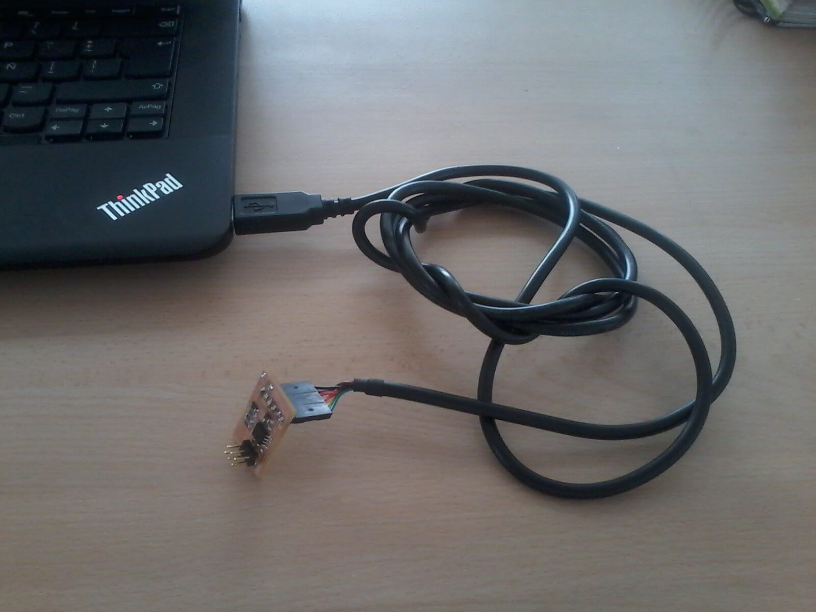
For programming the board you need the C and makefiles, you can grab them from this week class web, download them and put the files in a folder anywhere on your hard drive. Then open a terminal window and change directory "cd" to the folder where you save the files from before. Once there plug both FAB ISP and FTDI cable (check for corresponding black wire with GND pin and red with VCC pin, otherwise you can get your board fried) and in the terminal execute the following commands: To schedule our sensors, we are going to take as example the temperature sensor. What we do is to enter the page: http://academy.cba.mit.edu/classes/input_devices/index.html And we download the files .c and "make" We connected the FabISP and the FTDI cable to the card as in the following image: Then we opened the console of UBUNTU and we going to the folder where we have the files. We write in the console: sudo make -f hello.temp.45.make program-usbtiny. We obtain: