


"Double sided layer - PCB Milling Machine"
After spending many hours thinking about my final project proposal I decided to build a machine that can make double side PCB boards easier, as current machines usually finish one side of the board first and then the user swaps the board side being careful to keep the pcb same location. My project seek to reduce or even eliminate the time spent changing the side of the board using a camera to align the PCB board on the work area.
A. Problems and difficulties
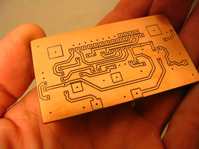
One of the main problems when designing an electronic board is the distribution of the components and routing their paths, this is easily solved by designing a double sided PCB. However in this process both sides must be aligned, otherwise the holes and vias in each layer won't match this usually happens when turning the boards manually.
B. Some inspirational references
A list of references where I take some of my inspirations to make this experiment and for further research:
- Patrick Thorn - MDX40A Rotary Axis
- Mikey Sklar - Double Sided PCB CNC Milling
- FlatCAM
-
http://flatcam.org/manual/procedures.html#side-pcb
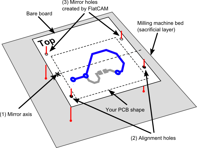
The main idea behind this process is to ensure that when you turn your board around to mill the bottom side of your PCB it will be perfectly aligned with the top side.The alignment is accomplished by using alignment holes/pins. These are holes on your board and on the milling machine bed (typically a board made of wood, known as “sacrificial” layer). The pins are used to align the holes on the board to the holes on the sacrificial layer. The holes are always symmetrical across a mirror axis. This ensures that when you turn your board around, the board can be aligned using the same alignment holes as before.
- HungSic Jang - Homemade CNC ATC Test Automatic Tool Changer
C. First concept ideas
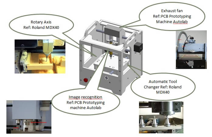
To do this we will design and build a "Double sided layer - PCB Machine" This machine can perform drilling, milling and routing any PCB for a maximum area of 10x10cm. Additionally it will include a system that will rotate the boards for routing the back copper layer. This prototype will also have an automatic tool changer and an extraction fan
D. Improvements:
- Automatic Tool Changer
- The prototype system will include an automatic tool changer. For example, in one work routine, it can mill the PCB and then drill holes without sending a new command from the PC.
- Rotary Axis
- The machine will also have a rotating system which will allow routing double-sided PCBs more easily, without the need to remove the board and relocate it in the same location and angle.
- Image Recognition
- Another tool that the project will have is a camera that recognizes a pair of drill holes that will be made on the board. Then camera can verify that the board is properly positioned. These holes will also create a reference point in the X and Y axis that will be used to recalculate the paths for milling and drilling the holes.
- Particle Extraction fan
- This machine will have an air extractor system that absorbs the copper particles removed from the plate.
E. Possible materials, components
Below you can find a list of possibles materials, components and boards that I pretend to use. There are another ones that could possible appears along the course.
- Micro Environment materials
- Wood, Plastic, Acrylics, 3D print board cases,
- Other Components:
- Power Source, RGB Leds, Electrical filaments, Electronic components
- Sensors
- Software:
- OpenCV (Open Source Computer Vision), Processing for local testing and rapid prototyping
F. Digital Fabrication Processes
Computer-Aided Design, Computer-Controlled Cutting, Electronics Production, Computer-Controlled Machining, Electronics Design, Molding and Casting: for bio light containers, Composites , Embedded Programming, 3D scanning a printing, Input devices, Interface and application programming, Output Devices, Networking and Communications
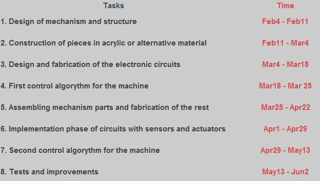
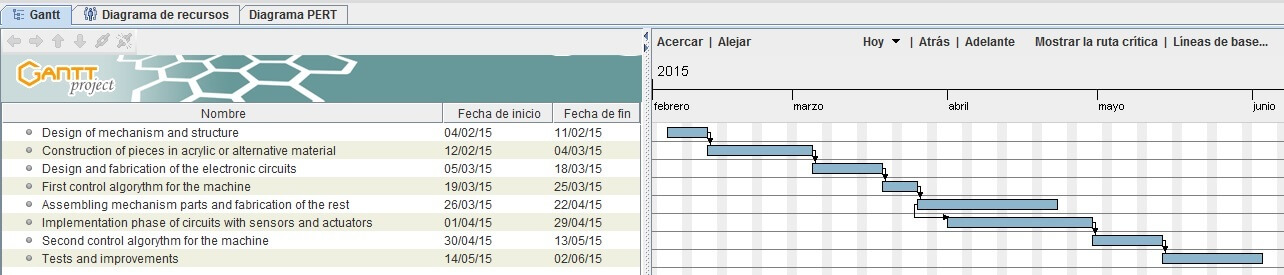
G. Schedule
The main idea is to develop this project over the journey of Fab Academy 2015. Many of the learning processes are included so I will take as an opportunity to experiment with other ideas as well.
Here we go Fab Academy!!!