

FOURTEENTH WEEK ASSIGNMENT
 |
 |
 |
 |
Interface and Application Programming
For
this assignment I first made a fabduino, then it was programmed so that
it could read 2 analog input and send the values through SERIAL
COMMUNICATIONS.
The second stage consisted of implementing an interface for 2 analog signal, first I tried to display only numerical variables, then to represent the variables simulating an analog instrument.
As an additional task I´m planning to buid my own USD FRTI cable, which is very necessary for the communication of our fabduino.
BUILDING A FABDUINO
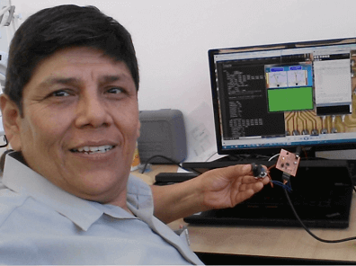
The fabduino was built with the assistance od jose de los Rios, a fablab instructor at TECSUP.
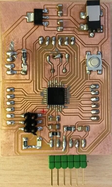
It has been a week of hard work, but you can see the satisfation in my face. I´m plannig to use this in my final project.
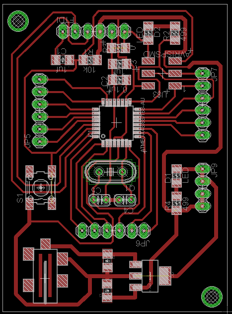
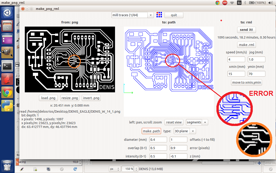
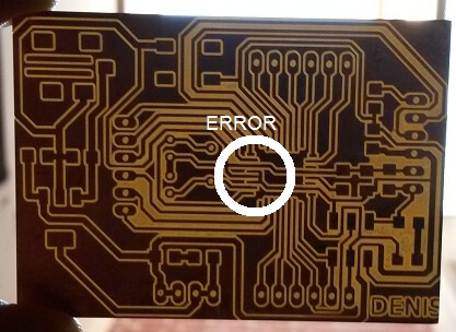
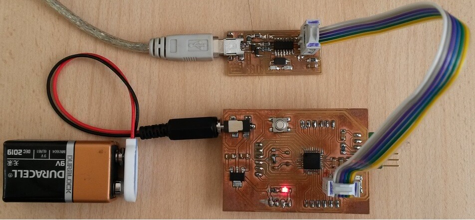
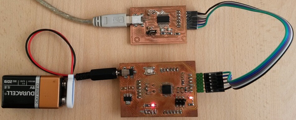
I built 2 boards, the first was ruined by the MODELA in which 2 tracks were too close together below the ATMEGA 328. You can see this error in the pictures.
The attached file has these problems already corrected.
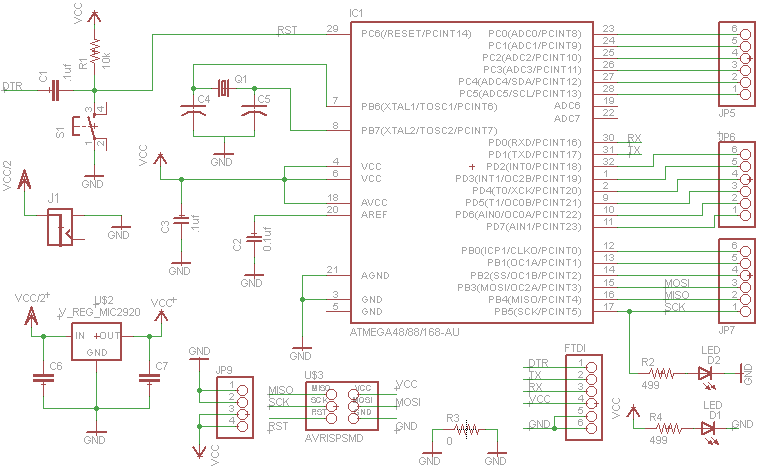
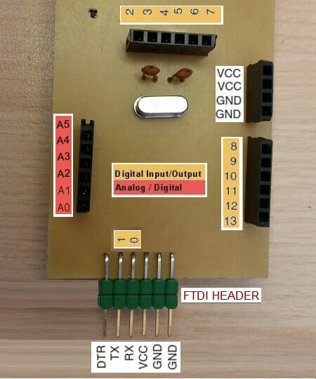
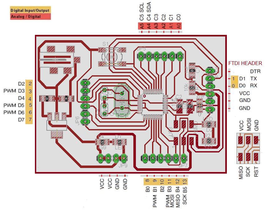
Our fabduino will have the connections as follows:.
Burning the Boot Loader
To burn the bootloader connect the programmer to the FabISP.
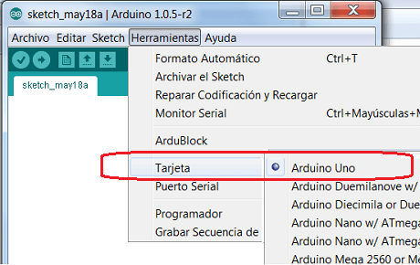
Choose the board type. For an ATmega328 (with a cristal of 16MHz) correspond to an Arduino UNO board.
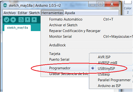
Then choose the programmer. (In my case FAB ISP)
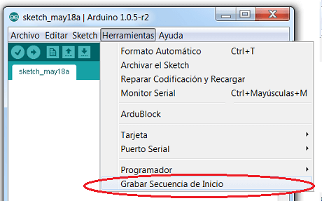
But when trying to download burn the bootloader appeared a mesaje in the IDE Aduino:
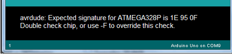
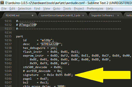
This problem was solved by opening the avrdude.conf file using Sublime Text. I had to change line 9245.
The original line is: signature - 0x1e 0x95 0x0f;
The new line is : signature - 0x1e 0x95 0x14;
/ Sending analog input 0 to the serial port
potPin int = 0; // number of analog input
potPin2 int = 1; // number of analog input
void setup () {
Serial.begin (19200); // Set the transmission rate to the port
}
void loop () {
int val = analogRead (potPin); // val as the read port value
val = val / 4; // Condition the read value to fit the window size
Serial.write (val); // Sends val Port BYTE format
int val2 = analogRead (potPin2); // val as the read port value
val2 = val2 / 4; // read value 2
Serial.write (val2); // Sends val2
delay (75); // Wait 75 ms
I show below manufacturing.
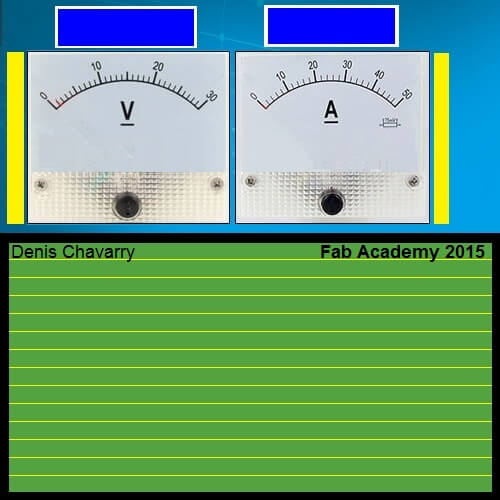
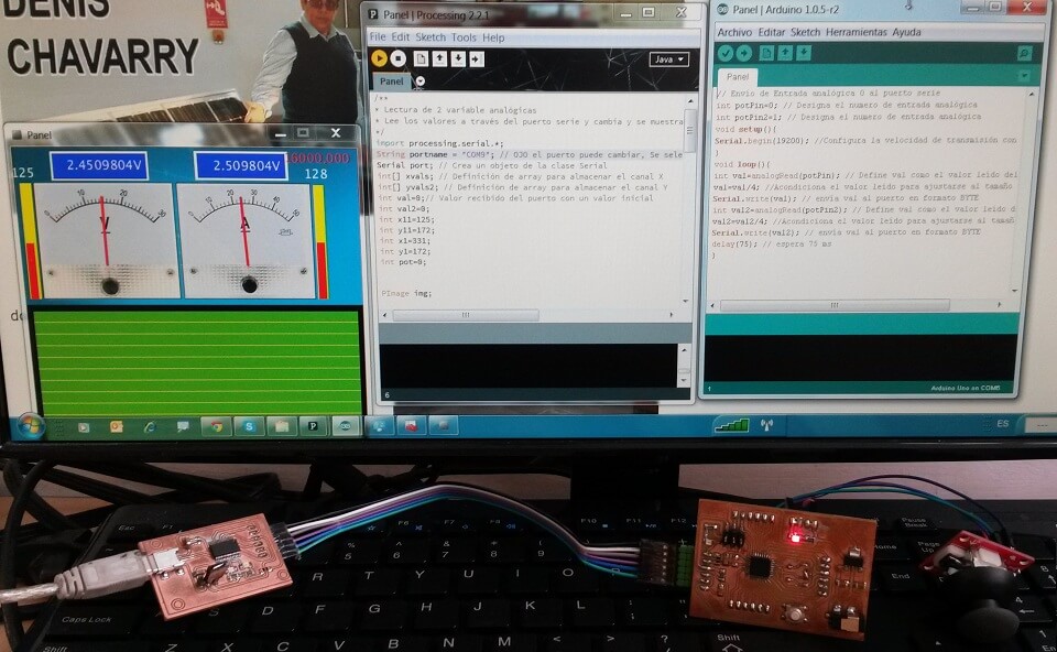
Program PROCESSING allows me to see 2 analog variables that are sent from the fabduino via SERIAL COMUNICATION.
This interface shows the values of the analog signals in numeric format (between 0 and 255), in analog format it shows indicators on an instrument and it also shows the plotted values on the time axis. The files for processing and imaging are found HERE.
* Lectura de 2 variable analógicas
* Lee los valores a través del puerto serie y cambia y se muestra como valor analogico digital y ploteo.
*/
import processing.serial.*;
String portname = "COM4"; // OJO el puerto puede cambiar, Se selecciona el puerto por el que se realizará la comunicación con fabduino
Serial port; // Crea un objeto de la clase Serial
int[] xvals; // Definición de array para almacenar el canal X
int[] yvals2; // Definición de array para almacenar el canal Y
int val=0;// Valor recibido del puerto con un valor inicial
int val2=0;
int x11=125;
int y11=172;
int x1=331;
int y1=172;
int pot=0;
PImage img;
void setup()
{
size(500,500);
// Images must be in the "data" directory to load correctly
img = loadImage("fondo_panel.jpg"); //la imagen tiene 500x233 pixels
// Abre el puerto conectado a la tarjeta
port = new Serial(this, portname, 19200);
}
void draw()
{
image(img, 0, 0);
if (port.available() > 0) { // Si el dato a leer está disponible
val = port.read(); // lee y almacena el valor
val2 = port.read(); // lee y almacena el valor2
}
{
// Dibuja la figura 1
float angulo1=(val2/153.7); //el angulo debe estar en RADIANES 255 a 90° = PI/2
float x21=x11-(100*cos(0.76+angulo1)); //43°= 0.75049 rad
float y21=y11-(100*sin(0.76+angulo1));
strokeWeight(4);
stroke(255,0,0);
line(x11,y11,x21,y21);
strokeWeight(1);
rect(8,223,11,-val2/1.5178); // /1.5178 es para ajustar en la barrra 255 a 168 de la altura
fill(255,255,255);
textSize(18);
textAlign(RIGHT);
text(val2, 29, 43); //valor 0-255 encima de la columna
text(5.0*(val2/255.0)+"V",188,32); //valor de entrada analoga 0-5V en Voltios
fill(250,0,0);
}
{
// Dibuja la figura2
float angulo2=(val/162.33); //el angulo debe estar en RADIANES 255 a 90° = PI/2
float x2=x1-(100*cos(0.75049+angulo2)); //43°= 0.75049 rad
float y2=y1-(100*sin(0.75049+angulo2));
strokeWeight(4);
stroke(255,0,0);
line(x1,y1,x2,y2);
strokeWeight(1);
rect(435,223,11,-val/1.5178); // /1.5178 es para ajustar en la barrra 255 a 168 de la altura
fill(255,255,255);
textSize(18);
textAlign(RIGHT);
text(val, 456, 43); //valor 0-255 encima de la columna
text(5.0*(val/255.0)+"V",388,32); //valor de entrada analoga 0-5V en Voltios
fill(250,0,0);
}
float pot = (val*val2);
textSize(18);
textAlign(RIGHT);
text(pot, 490, 20); // potencia
}
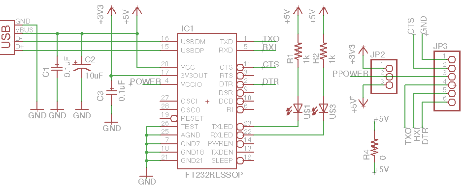
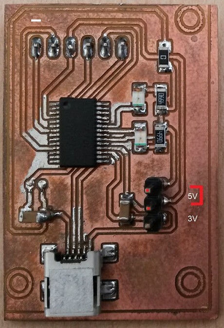
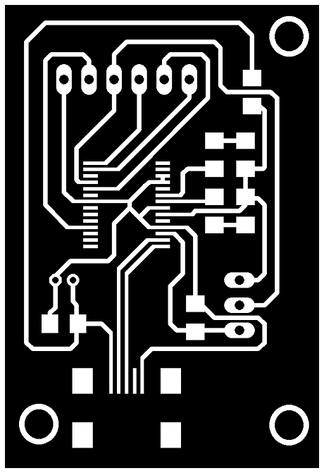
This FTDI cable is necesary to be able to program the fabduino, and we only have one at Fablab TECSUP so it was importand to build ours.
The files to build an FTDI cable were downloaded from Jose de los Rios´s web site of his final project. The board files were made with eagle, you can download them here.
ASSIGNMENT COMPLETED
Task accomplished.
Finally, I have two cards manufactured and a interface program.
Finally, I have two cards manufactured and a interface program.