
Claudia Aguilar
FAB ACADEMY 2015

CREATING AN OUTPUT DEVICE
For this week we have to add an output device to a microcontroller board that I have designed and also program to make something. For this and taking into acount my inexperience in electronics I desided to analize the existing examples and take it as a start point.
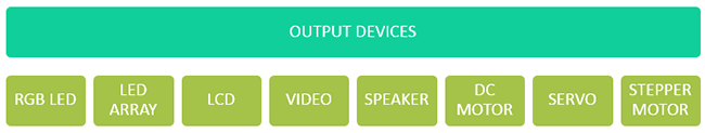
The output devices I have for choosing are RGB LED, LED array, LCD, video, Speaker, DC motor, servo, Stepper motor. In this case I'll be working with the speaker example as my final project has to have sound or music.
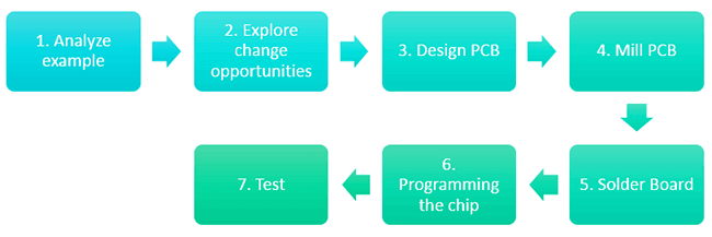
Next you can se the process I'm having starting with an analyze phase where I study the existing example, then I'll explore the modification opportunities I have and understanding them I can generate my own Output PCB.
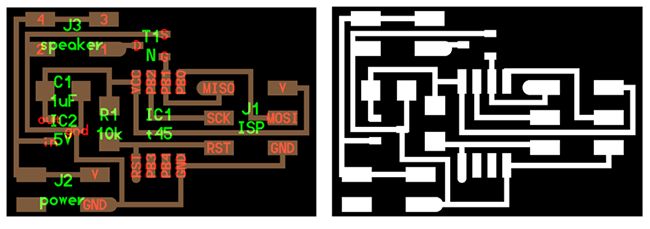
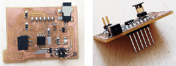
As I decided to use the Speaker example you can see next the existing speaker board design.
Once having this, I also analize the last weeks assignment INPUT DEVICE, so I can have an OUTPUT but also introduce a FTDI to provide an other power source and also a way to interact with an interfase.
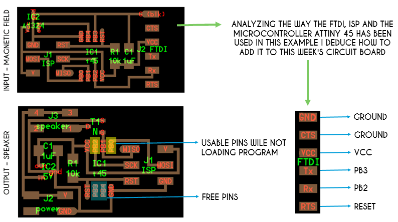
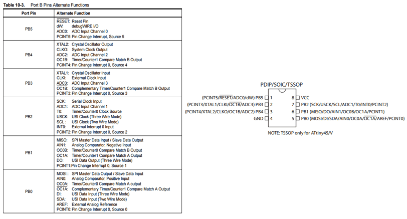
This adaptation is purely by deducing the connections in the circuit board. To prove everything is ok I also studied the Attiny45 datasheet to see if all the pins of the microcontroller were properly used.
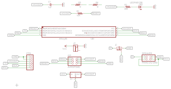
Once having the complete idea of the board I used EAGLE to generate the scheme of the board.
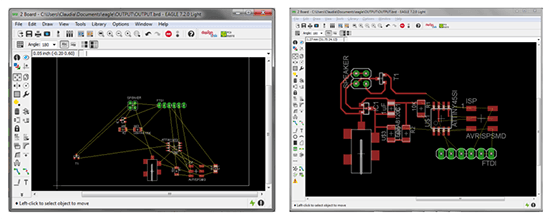
Then I generate the board design. You can see next some images of the design process.
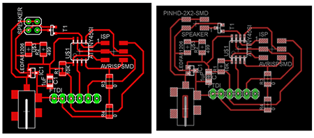
After lots of test you can see next the final design which had only one change in the speaker pins.
You can downoad here the EAGLE files.
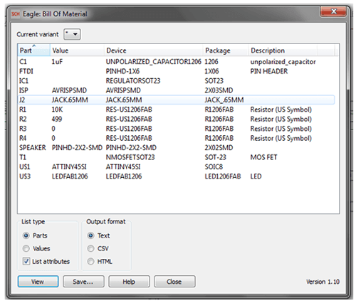
This week I also learned the comand RUN BOM wich means Run Bill of Material. This way I had the complete table of components used and then search for them in the laboratory inventory.
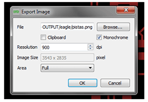
This week I also had to recall how to export the PNG file out of the board design on EAGLE. Next you can see the dialog window for it.
You can download here de PNG files.
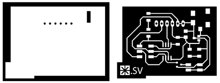
Once having this file you can mill in the MODELA. You can see the instructions for this in my WEEK 4 DOCUMENTATION.
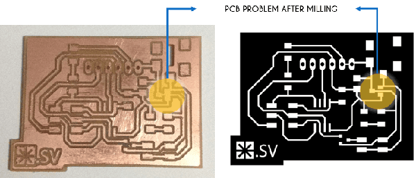
You can see in the next image the only problem I had after milling the board. It happens that some component supports were together so I had to fix the problem just removing carefully some material to generate the routes as they had to be. Also I had to be very careful with this in the moment of sold the components.
You can see next the final board with all the components in.
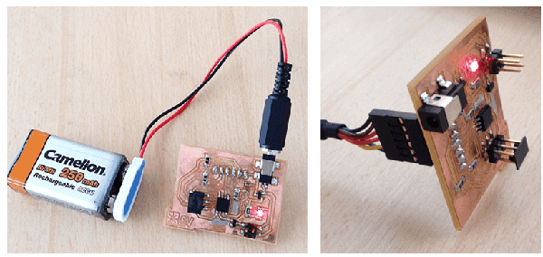
Adding the FTDI to the board has two benefits: one is having a communication with the computer and the other is having an other power sources. To prove it you can see in the images the red LED on which shows the current flow on the circuit.
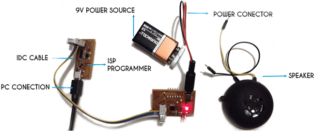
Having the board ready we can now connect it to the ISP, generate and load the Programming files to make it work.
In this case I use the same files as the existing board because beating the programming code is steel difficult for me.
I steel want to generate my own music for this assignment so I found this tutorial that teach you how to generate a C code from music. You only need a MIDI file to generate it and then you can load it to your chip with Arduino.
You can downoad here the programming files used for this assignment.
Next you can see the programmed circuit board working.
Click here to see this class content
Click here to see this class recorded video