Week 4
Electronics production
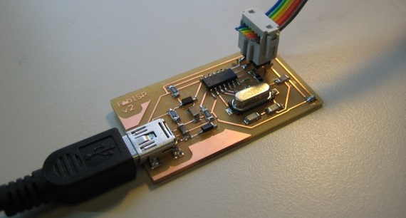
This week I had to make a FabISP in-circuit programming.
For this I followed the instructions of
David A. Mellis.
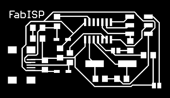
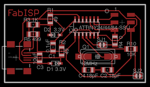
I started by downloading the .png files (photo below) of the circuit and the contour. I then used the Fabmodules to create the G-code that the cnc mill need to machine the pcb.

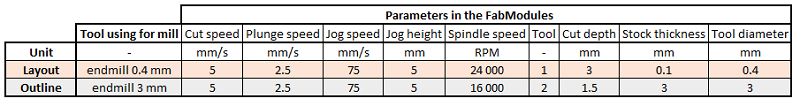
We chose the parameters with the experience of LabManager, paying attention to the size of the tools used, the thickness of the pcb and features of the cnc mill. In the Happylab of Vienna we have a CNC mill BZT PFK 1607 PX and to use it I chose the parameters below.
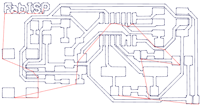
You can see the path followed by the tool on the image below. Everything looked good according to the drawing.
I saved it as an .NC file but it was not finished. The FabModules calculates distances in inches but the
CNC mill operates in mm. So I had to make some changes. I described those changes in the mini tutorial below.
************************************************************

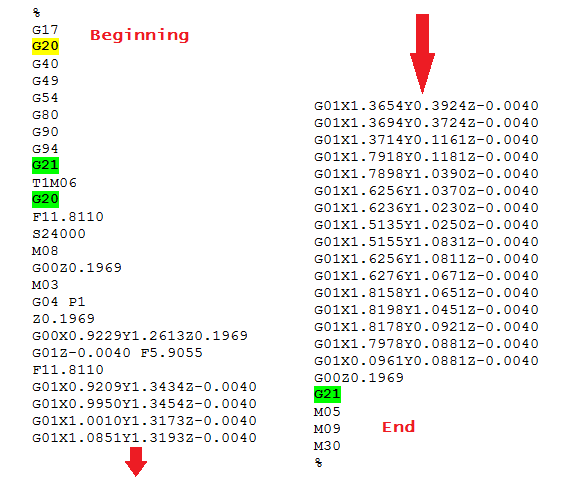
- Open the G-code on WordPad
- G20 means "in inch" so I removed the yellow G20 (look just below)
- G21 means "in mm" so I wrote the green G21
- T1M06 is the tool change so the machine will mesure the tool in mm
- After, the tool will move to machine the piece but the distances are
in inch so we have to put the green G20 just after the tool change
- All commands are in inch up to the end but we add the second green G21
at the end because the machine can't change the units by itself and it's better to calling into mm for the next who will
have a nasty surprise otherwise (:
************************************************************
And here is the final G-code I used : .
.
We did the same thing with the contour and here is the second G-code :
.
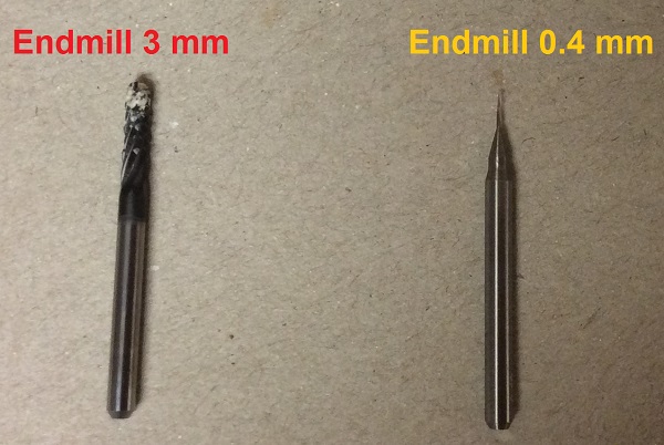
We couldn't make only one G-code because the FabModules can not consider different tools and we needed a tool to etch the board (endmill 0.4mm) and another to cut the contour (endmill 3mm).
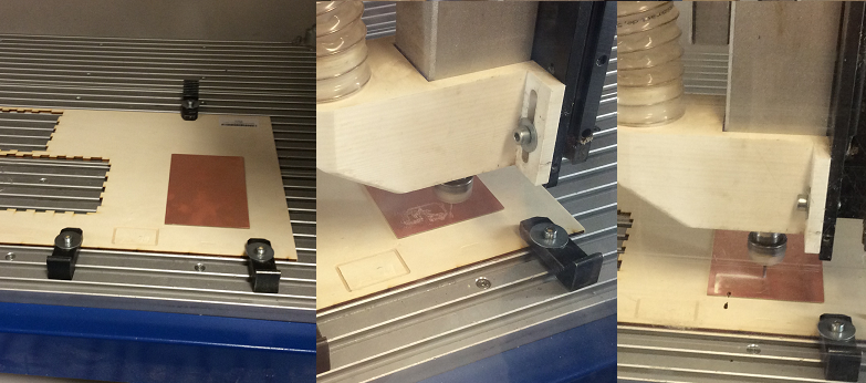
So I fixed the pcb with tape on a piece of wood and then I fixed the wood in the cnc mill.
At this time the challenge was to define the origin for machining since the goal was to remove only
a thickness of 0.1 mm. So by placing originally just 0.1mm too high, nothing was going to be machined.
The method proposed by Neils during the last lecture did not work on our mill so we tried slowly down
the tool and drag it until a fine stripe is emerging on the pcb.
After that we started machining.
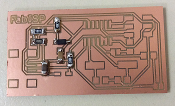
We got what we see below.
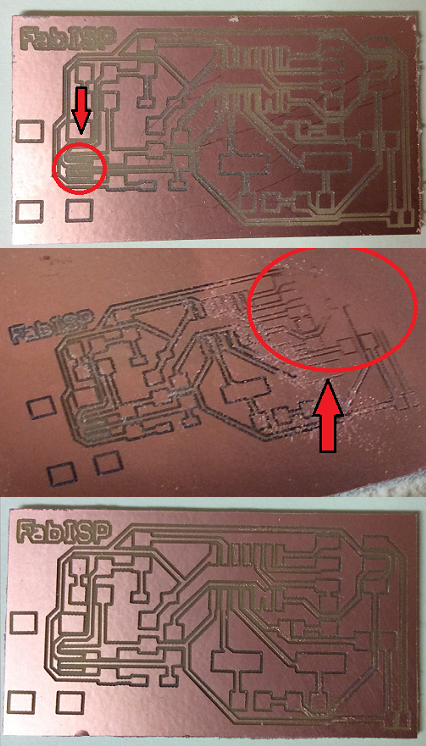
The first try was not successful because as we can see, the circled portion in red was too thin.
So we changed the settings to get the G-code to obtain thicker lines, ie the tool had to pass further the edges.
The second trial was better at the location of the thin lines, but this time the right part of the circuit has not
been properly machined as can be seen in the second picture.
So we decided to change the tool. Instead of continuing with the graver (with a hint of 0.2mm that we thought more
accurate but difficult to use to get a good result), we used an 0,4 endmill. And the third try was successful as
we can see on the third picture ! We had no problem with the contour.
The LabManager ordered the components we needed on two sites: RS Components and Digikey.
So I soldered each component in its place with help of the diagram above.
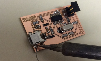
It was my first time soldering such tiny components in this way, I mean with SMD components.
And it really was not easy but after a few corrections with the multimeter, everything was good.
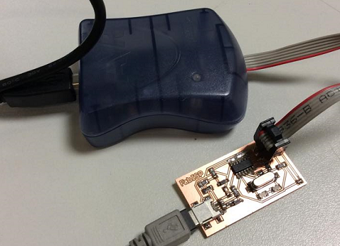
I then downloaded the AtmelStudio software. We connected the pcb to the programmer (that we ordered with the microcontrollers) and to the computer for power. So we were able to load the program into the microcontroller and apparently it works (:
Software and website used