Week 11
Output devices
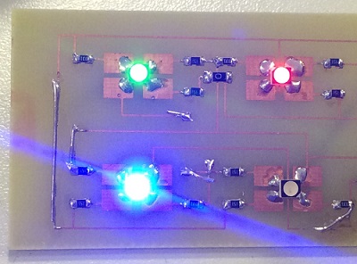
This week I decided to use some RGB LEDs (PLCC4 3 in 1 SMD LED) because this is what I would like to use for my final project. And as I will use 82 LEDs for my display, I started to study the method of Charlieplexing.
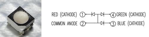
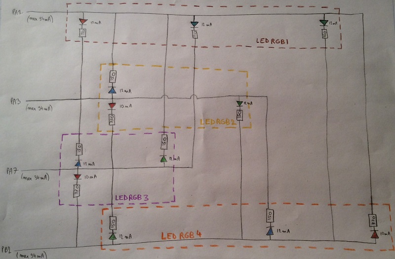
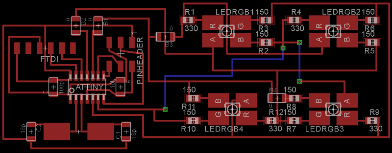
The first step was to design the circuit. I understood quickly the Charlieplexing method explained here but I had some problems because one LED RGB is in fact three simple LEDs but with the same ground ! And that was the bigger issue this week but I finally draw the circuit just below.
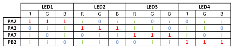
I created a table according to my circuit to know which state I have to use for which pin in order
to light the LEDs and choose the color.
- 1 correspond to Vcc (5V)
- 0 correspond to Gnd (0V)
- i correspond to input (hight impedance)
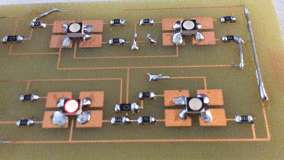
I then designed the schematic by using the same components than in week 10 but I removed the photoresistor and the simple LED to put four new RGB LEDs (with the associated resistors).
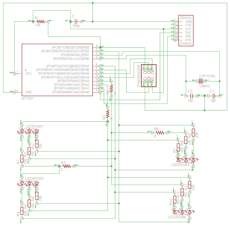
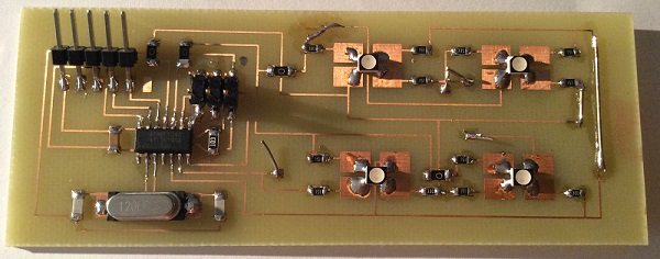
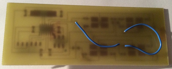
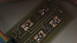
And I continued with the board, which was really not easy to make. So I used 6 bridges : 4 0ohm resistors (B1, B2, B3 and B4) and 2 wires (in blue).
I used the same chemical method as last week to build my pcb and I had no problem to make it this week. Here is the pdf I used. And here is the eagle file.
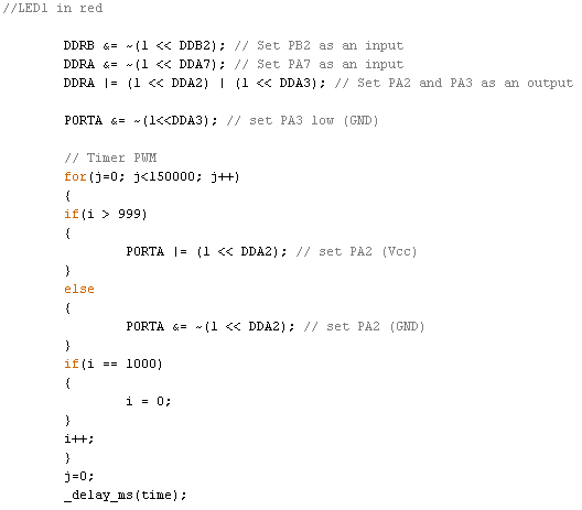
I started to write a program, according to the table above and here is the code. There is an extract just below.
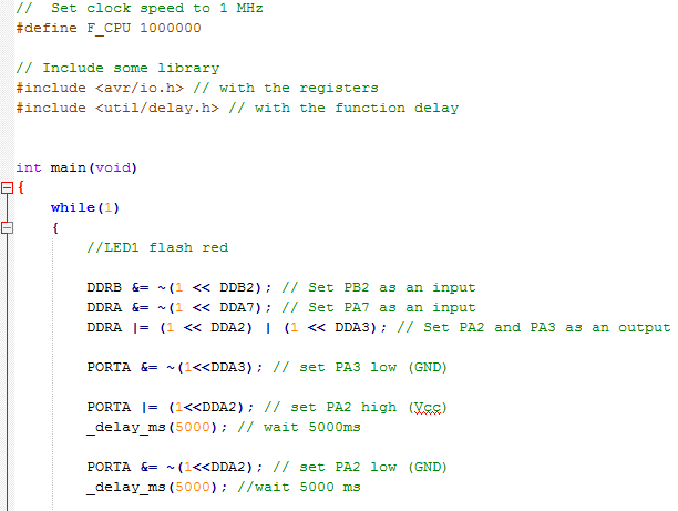
But first it didn't work. The LEDs light up but not like I wanted. There were always three LEDs turned on, the one I wanted plus two other (which lighted much less). So I looked at my circuit and I think I found the problem. If you look at the circuit drawing on the top of this page. If I set PA2 as an output, PA3 as an output, PA7 as an input, PB2 as an input and then set PA2 to 1 (Vcc) and PA3 to 0 (GND), the red LED of the LEDRGB1 should light up. BUT the blue LED of the LEDRGB3 and the blue LED of the LEDRGB4 could light up too !!! Because the 5V can go through an other LED and arrived to PA7 and PB2.
I first thought that I have made a mistake but I found
this page which
explains that it's normal. But I have to use a timer PWM in order to reduce the lighting time of the
LEDs I want to turn on.
I then changed my program by adding a PWM to turn on an LED.
It worked for the red LED but not for the other colors !!! The problem is that the blue and green LEDs have not the same voltage as the red one. So I wasn't able to reduce more the green light without turn it off.
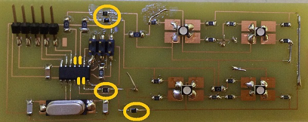
This is at this moment that I found this. I found someone who had the same problem as me and he solved it by putting a resistor (330ohms) just after each pin of the microcontroller which are used for the charlieplexing. I put four 150 ohms resistors just after the four pins I used and now it works perfectly !!!
And we see the lights even when it's not dark in the room (:
Software and website used