Week 10
Input devices
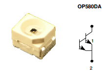
This week we continue with electronics devices ! The goal was to mesure something with a sensor we chose. I decided to use a phototransistor (Silicon Photo Darlington in PLCC-2 Package OP580DA).
I had to design and make a new board adding a phototransistor and an LED. My goal was to successfully
write a small program to measure the brightness in first. But then ensure that the LED shines
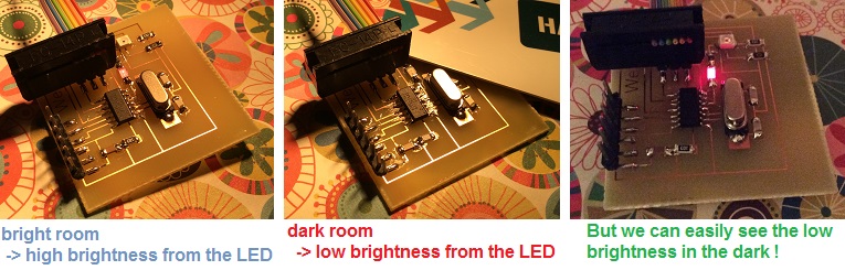
stronger when the sensor detects a lot of light (day) and it shines less strong when it is dark
(night). That's why I added an LED, to test this feature I would like also added to my alarm
clock (final project).
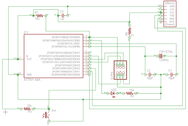
So I again use Eagle in the same way at week 6. I used the same components but removing 2 LED and
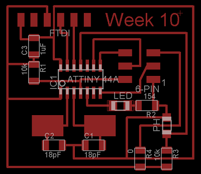
the button and adding a phototransistor. I made the schematic and then I created the board.
I used the same chemical process that at week 6 with the same steps I have already detailed before.
You can download the pdf file I used here. Don't forget to print
it in mirror ! And here is the eagle file.
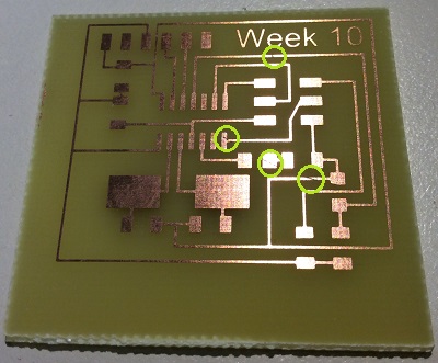
The first try (on the left, photo below) wasn't so good, I don't know why but maybe it's because I
have not left the pcb in the developer adequate time. Or maybe the Sodium Persulfate bath was too old
because to obtain the left one, I put it in the bath during approximatly 1h.
The second try was much more better after only 20 minutes in a new Sodium Persulfate bath!
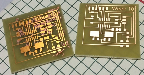
However, one can observe some micro-cut (in green circles), which is probably due to the poor initial quality of the pcb used but with the soldering iron this problem is quickly solved (:
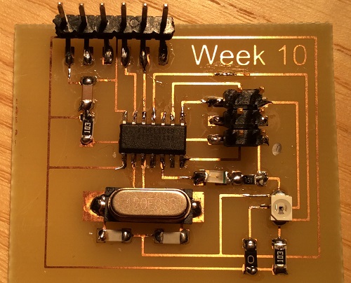
It only remained for me to solder the components.
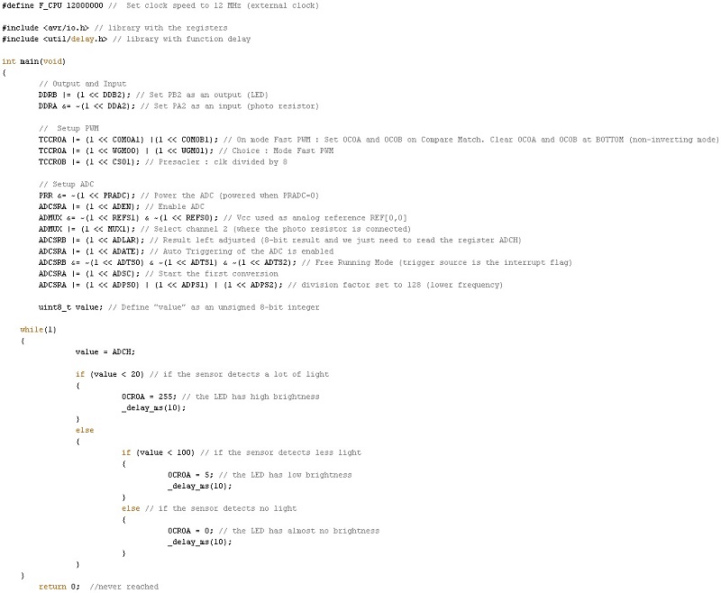
And I had to write my little program ! For this I started to read the parts I needed in the microcontroller
datasheet to understand how work the ADC and the Timer with PWM.
I wrote this program (see below).
I used my arduino UNO to powered my board and my FabISP to program it. This time I used the Arduino software and everything worked perfectly ! Just one thing, I didn't find how to change the fuses with arduino to use the external 12MHz clock instead of the internal 1MHz of the ATTINY44A.
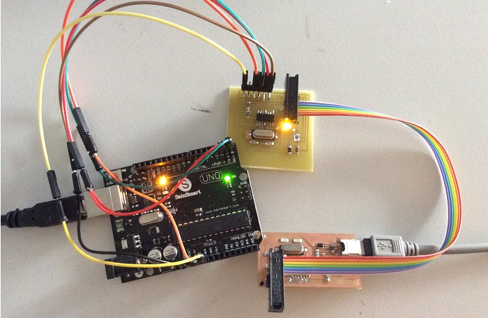
The concept is to vary the brightness of the LED according to the brightness of the room (so that the screen does not wake me up during the night for example).
I was really surprised that everything worked like I wanted :)
You can see the three states : high brightness and normal brightness on
the first gif, normal brightness and low brightness on the second gif.
![]()
![]()
Software and website used