
You can make a wired connection, or wireless. Communications and protocols are the same. For wireless you need extra piece of hardware.
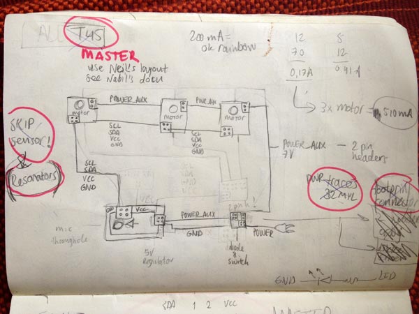
------------I want to create a master-slave configuration based on the MIC board from the input devices week and the stepper board I did for output devices. The idea is that when you blow into the mic, the motor on the slave is activated, moving a small mechanical bug in a bell glass frame. I can build on this for the final project by producing more slaves (I want three ideally). Because I'm keeping the final designs small and light I guestimate for now that the stepper motors will do if I supply enough power for a strong torque. But I can modify my choice of materials based on this decision without problems.
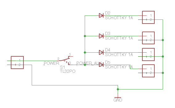
I will make a separate switch board to connect an adapter to power all the boards. The adapter is 7V/600mA. One stepper motor pulls 170mA, three motors at the same time will pull 510mA. So everything needs to be a bit bigger and better to support that.
Figuring everything out...
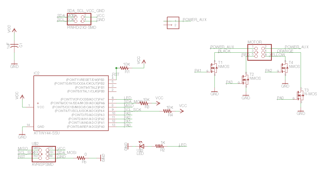
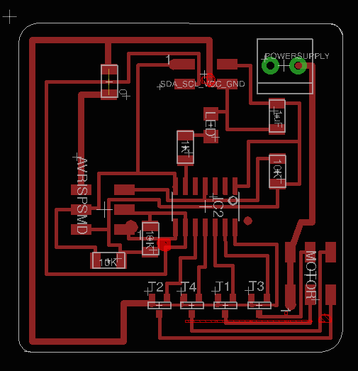
I will start with getting one slave to work and then at more towards finals. On the motor boards (slaves) I need to have:
The master will control the motors and will have the MIC sensor to do readings on it.
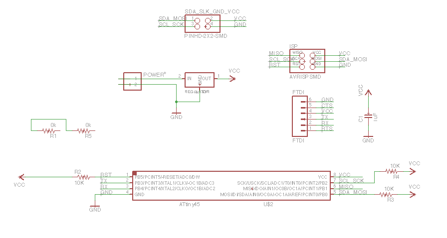
I had to look carefully at my components, wirings and connectors because I will be pulling a lot of amps with more than one motors. I looked at all the datasheet and calculated the current for these parts of the circuit. Then I found out a bit late the I2C is not supported for ATTiny44. But looking at the documentation of Nabil it looks like it's possible to communicate with t44 slaves if you have a t45 master. I need this because to control a motor I need more pins than the tiny45 can offer. I changed my schematics and layouts again to fix it. For the master board it meant that I had to skip including the Opamp/Mic sensor parts because they wouldn't fit either. That's actually a blessing because it would become a pretty complex board.
I originally wanted to keep a resonator on board rather than to accurate the clock in the code. Zaerc has written some code to do that easily. Let's see how it goes. But because I have to use an ATTiny45 for the master (I2C protocol not supported on 44) I had no choice and not enough pins to do it.
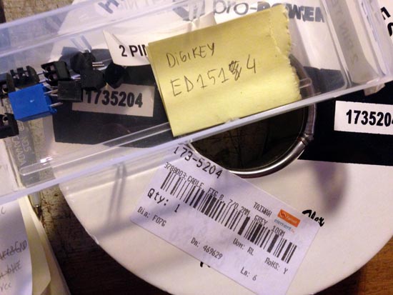
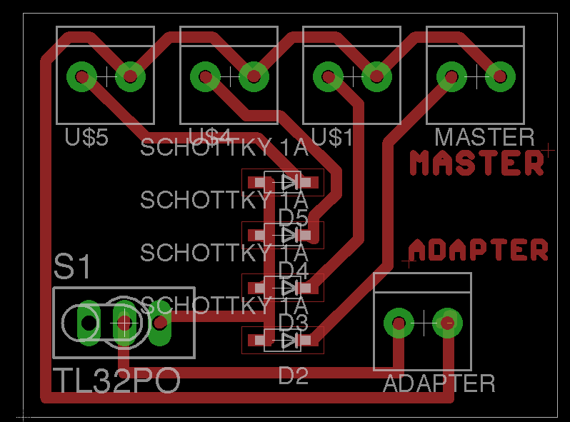
I had to find a footprint for the 2 pin terminals, I found one with 3.5mm dimensions like the one I need in the adafruit library called ADAPTER 1X2-3.5MM package 3.5MMTERM that I think will work. But otherwise this is useful:
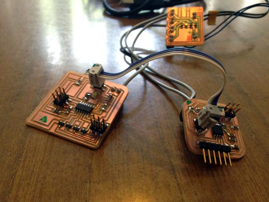
All looks well, I had to eventually throw some stuff off the boards because of a lack of pins. I'll have to make a separate board for sensor input but that can be done without too many problems and can be added without making an extra board even. I have quite some wires running between boards but we'll deal with elegant solutions for that later.
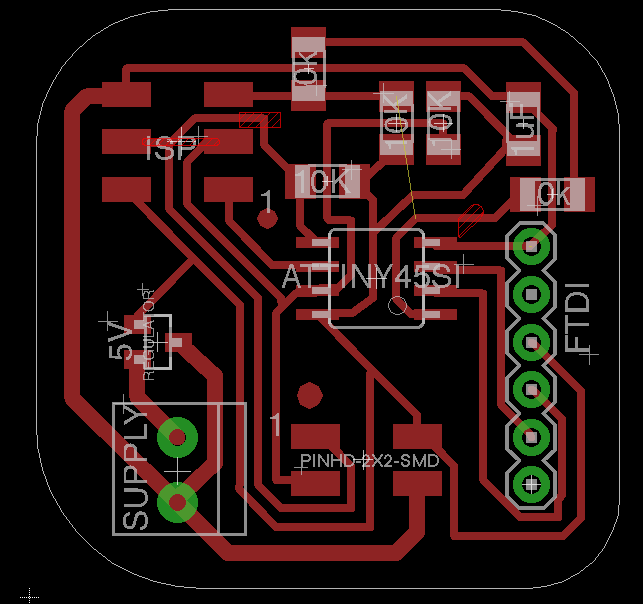
It didn't want to mill the cutout because I'd left too little buffer for the size of the milling bit. By telling the modules that the milling bit was smaller than it actually was I could trick it. But next time I should make the margin for the png slightly bigger.
All good, had to look carefully about what goes where.
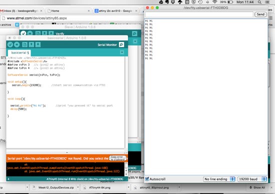
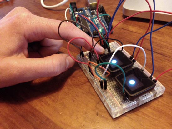
Before trying to set up the communication I debugged the board:
Refer to Neil's C and code. Or look into Wire library in Arduino: TinyWireM (master) and TinyWireS (for Slave). Big bonus of this protocol is that there are supported libraries that work with Attiny. And it's very efficient in terms of wiring (only two wires to support many slaves).
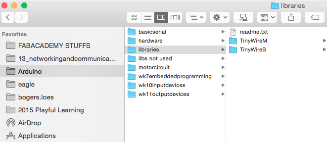
It's not super easy to set it up. I downloaded the library for the Master45 (default) and the modified Slave44 version via this webpage. But I struggled a bit with importing it and getting the filestructure correctly to access the right lib for each. This is what it should look like.
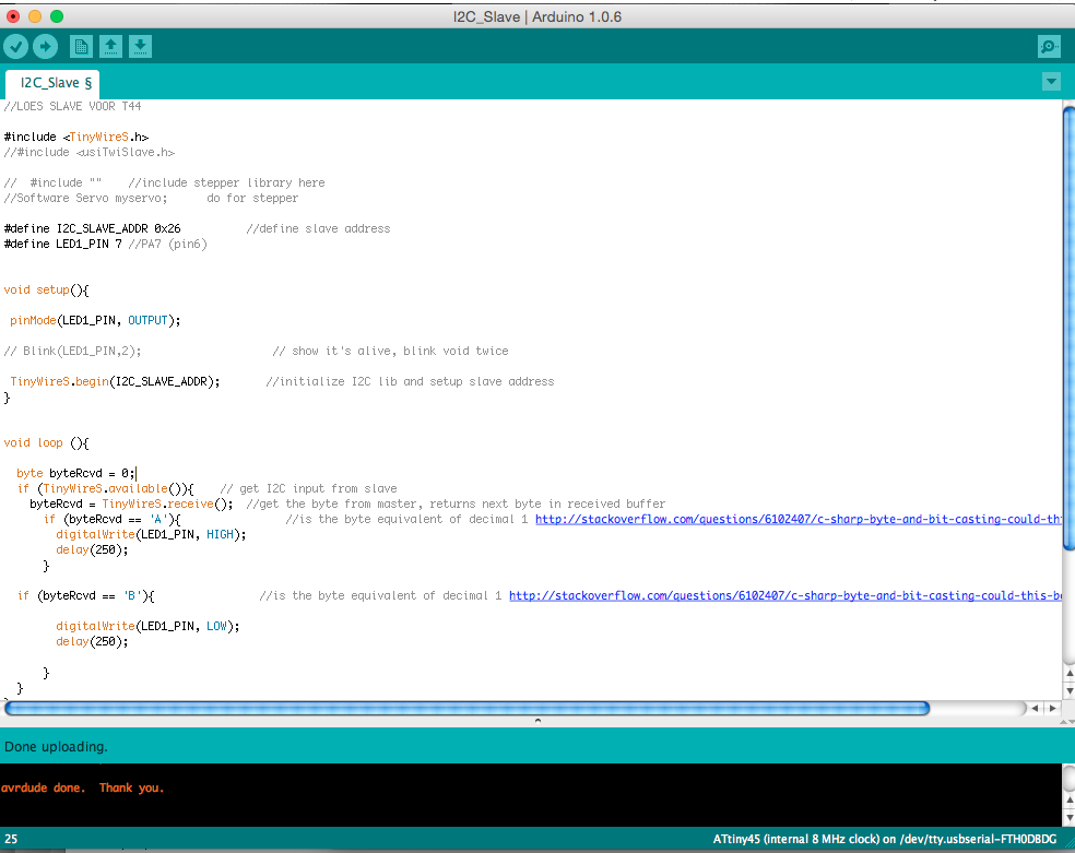
then I cobbled together sketches from the arduino examples and started testing it out. I just want to give input via the serial monitor and have the master transmit to slave who responds by blinking the LED.
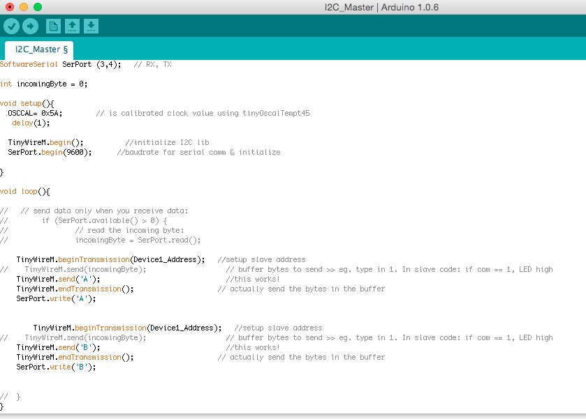
The first attempt I got the master sketch to do everything it's supposed to: it responds to serial monitor input saying "Online", "Starting Transmission", "Ending Transmission". So far so good, but no response from the slave yet. The slave sketch is obeying what I tell it in the setup: blink the LED twice to show you're alive. But then nothing. But actually all this serial stuff was just to confirm initializing a serial communication. So I simplified the sketch to just send a byte to the slave (1 in decimals = 0x01 in bytes).Then I got so far as getting the light on by sending 0x01 (decimal 1) to the slave. But it seemed a bit arbitrary. I calibrated the clock using this code by Zaerc. The best values were beteen 0x53 and 0x62. When you open programmer mode in calculator to add these up and divide by two you get 0x5A. In the setup you put this:
OSCCAL= 0x5A; // is calibrated clock value using tinyOscalTempt45
delay(1);
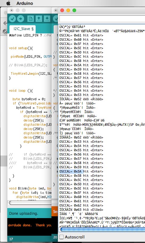
What I ended up with was this working code. But it gives very irregular on and off signals....
This is what that looks like. We checked with a program called Logic to see what signals are being sent up and down. It basically visualizes exactly what bits are being sent to and fro. Quite nice. But it didn't tell us much new except that it's weird. It looks like it's giving the same commands all the time where it should be alternating on/off. Thats also what the LED is doing so double weird.
I understand working with the libraries and the debugging but I would have to do more serious debugging to figure out why the communication is behaving strangely.
We went back into the boards and checked board by board that the were getting the right voltage, on the ICs and the right voltage on the higher power lines of 7-9V. We'd established that the adapter was broken, it worked earlier but when I plugged it to the boards, afterwards it wasn't working anymore which was a concern. We used the power supply in the lab. All the boards and the regulator on the master were working fine. But as soon as we mounted the stepper to the slave board it started pulling a lot of current. Something there needs to be looked at.
I debugged the boards by adding a bigger GND line from the switch board to the slave with the motor. (Before it was just going via the SDA/SCL/VCC/GND ribbon wire. But because a motor pulls a lot of current it would be better to have a big GND line so I added a jumper. And the regulator was busted so I replaced it.
I learned that keeping the FTDI communication and the I2C communication in different voids in the code. Eg. don't put a serialprintln command in an if statement using the I2C protocol.
Apparently you can send values between 0-255. Other values are not sendable. If you want to send values like a number, or a character. Use "char" variables in the code. Otherwise Bytes in hexadecimal values (eg 0x52), bytes are better.
Emma suggested I'd consider writing my own protocol to really control what is happening in the communication. The arduino library is nice enough but you don't have full control. If you know what it needs to do, might be worth writing something else. Simple boolean logic using two lines can already do 4 tasks. In another case. My classmate Frank Vloet managed to get I2C rolling between two ATTiny44s using C code that he collected and cobbled together. Pretty impressive hey Frank! I could draw from his research perhaps.
This note about the TinyM lib for attiny85 says it's default at 1mHz clock speed. I'm using 8mHz on the master! check here. Maybe this is the timing problem....so I changed the command #define SYS_CLK 8000.0 // [kHz] in the USI_TWI_Master.h file, and the command #define F_CPU 8000000UL in the USI_TWI_Master.cpp file. I removed and re-included the libraries. I re-burned the bootloaders on the ATTinys, and uploaded the code but unfortunately, the signal is still irregular.
I went back to a realllllly simple sketch to check and monitor the communication using the same code Till used this week:
It simply sets up communication between master and slave, and the slave gives alternating high or low values back to the master. The master prints it to serial. What comes out are a lot of 255s in a row, then a lot of 0s in a row. Instead of alternating 255, 0, 255, 0 etcetera. So even with simple code the problem remains.
I went on to play with I2C a little bit in the interface application programming week: I wanted to know how to interface a Microview (Arduino with built-in OLED display) with another controller. Using the Arduino toolchain however (shame on me!.. NOT. This was for fun and practice :)
CODE
And the board layouts and schematics
 SLAVE
SLAVE
 SWITCHBOARD
Resources: Nabil's servo driver board from last year
This is the Wire Library for Arduino. And here's documentation on how to use this library to encode the Master writer/Slave Receiver and the Master Reader/Slave Sender.
------------Uses signals between 0 and 13V. If there is no data, the signal is low (this is not the same for all standard.
Is the opposite: the signal is high when there's no data and it's between 0 and 5V
------------Asynchronous because you don't use an external clock, you're just sending data. RX to receive, TX to send and a GND if you want to share the boards' GNDS (Neil's board share VCC and GND. Direction is always TX > RX.
No clock? Means you need other rules to communicate, protocols. Eg number of bits. The signals we're sending are digital, HIGH or LOW, 0V or 3.3/5V. Note: the boards don't share a clock, but it's wise to give them each their own clock (the same type).
It's a synchronous data bus, with a clock! Means it uses separate lines for data and clock. To keep it synchronized. Requires 4 wires: SCK = clock,
You have a master and a slave. Master distributes clock signal. Main board is managing communication, then it's ok. If you need two way communication you will need a lot of wires.
There's an SPI library, but it's not developed for Attiny. You can use the shiftIn() and shiftOut() commands in the Arduino IDE. There's an example of someone who used Attiny85 for this assignment with this method. There's no example from Neil. Benefit from this method: more stable and accurate timing between boards because they share the clock. Minus: requires more wires.
------------------------Just two wires can support up to 1008 slaves. This is a very strong protocol. You need 2 wires: clock (SCL) and data signal (SDA). You send a minimum of two frames: 1) identify the slave (always), and 2) data to tell the slave (or more frames to do different things on this address. Packet > Frames > Bits.
Refer to Neil's C and code. Or look into Wire library in Arduino: TinyWireM (master) and TinyWireS (for Slave). Big bonus of this protocol is that there are supported libraries that work with Attiny. And it's very efficient in terms of wiring (only two wires to support many slaves).
Check the devices you use, if they support I2C the process can be relatively easy. It's a well-used standard.
Resource: Nabil's servo driver board from last year and how he used the module for the communications week as well. -----------------------
Look up documentation of other's and their examples. Most of the have a clock integrated, and already implemented protocols incl libraries to use in your code. Takes away some of the hard work.
