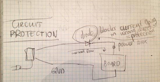
where to add a diode
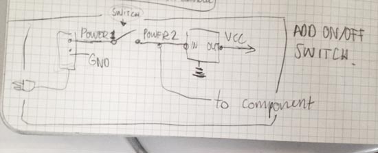
where to add a switch

I want to make movement. Different kinds of movement? Bonus! More motors controlled with one IC even better. So the plan: build the Unipolar Stepper circuit with the 4 N-Mosfets. Get it to work. If it works I can use the same board to drive a DC motor (connect it to POWER and one N-MOSFET), or 4...... One board, many different applications, many different motors that could potentially work with it.
Additionally: the Unipolar Stepper has properties that make it really easy to figure out how much weight you can put to the axis without blocking the motor. It will not work with too little weight, it will not work with too much. So easy to figure out what range of weight it is suited for.
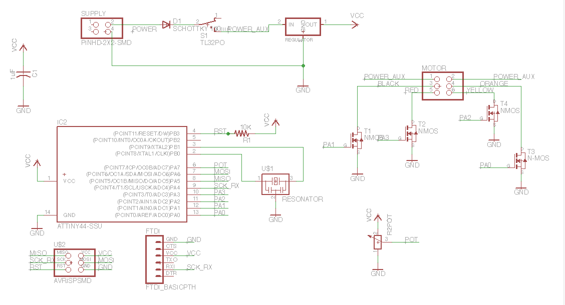
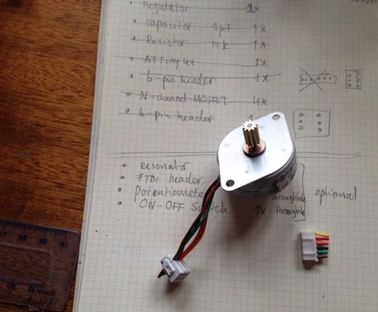
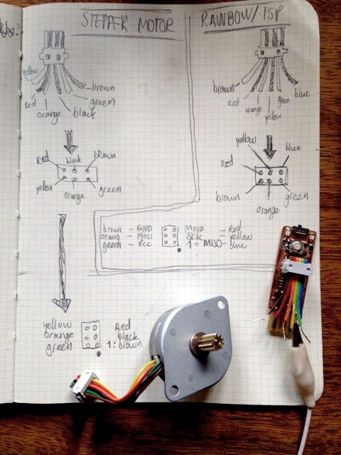
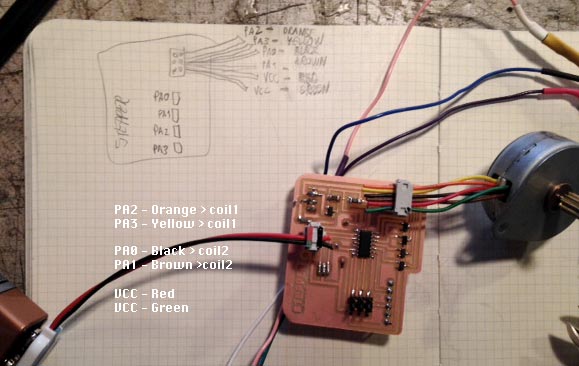
Making the schematic was a bit more complex than before because some things don't have straightforward footprints. The stepper motor for example came with a male connector we don't have a header for. So I clipped off the connector and added another one that can be used with a simple 2x3 6-pin header we also use for the AVRISP. I had to figure out which wire ends in which pin of the header first:
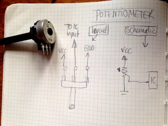
Also the potentiometer was asking for some special treatments. We only had a few lying around with no details on part numbers etcetera. I'm connecting it with wires. I picked a random potmeter footprint - throughole, so I can connect it with wires. I read through this wikihow: how to wire a potmeter to figure out what to put on pin 1,2,3 in schematic.
Then I was wondering whether you need to put the motor pins and mosfets on PWM pins to control the speed (with the values of the potmeter). I looked at the code of these arduino examples and saw that they use digitalWrite to control it, so I could conclude that the motors don't have to be on PWM pins (Neil's aren't either). So I could leave them as in the examples.
When you look at the code you see that it's controlling the 4 coils in alternating fashion, pushing it forward one by one with a varying delay (acts like PWM but with a digital write with a variable delay controled with potmeter). This instructable makes it really clear how the software drives the hardware.
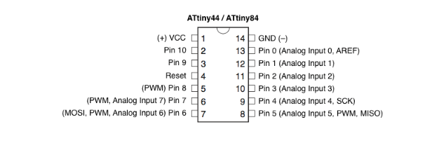
Pin for potmeter: any analog input pin: PA1:PA7 will work
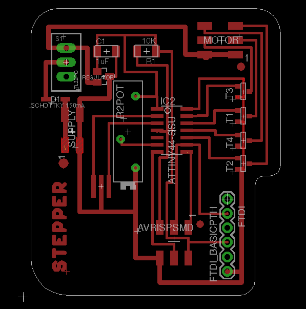
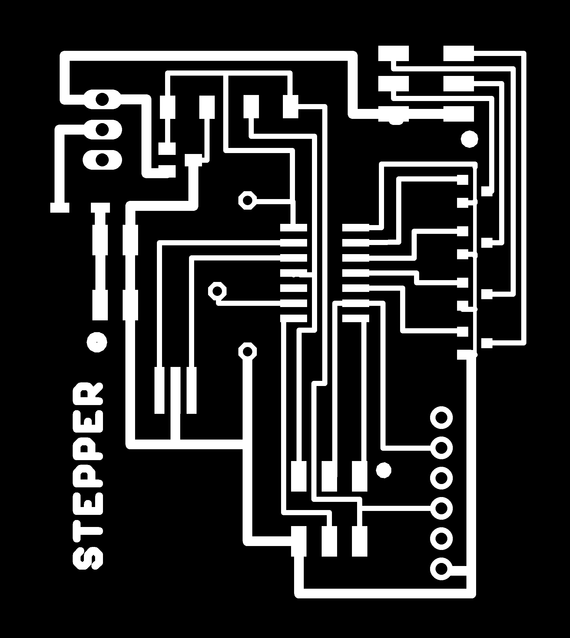
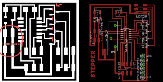
I wanted to improve my eagle routing technique a bit because I spent so much time on it the previous times. I looked closely at Neils example and handrouted everything. The extras that we on my board were then fairly easy to space by moving some stuff around and rerouting here and there.
I'm slightly unsure about the traces going underneath the MOSFETS. I can see Neil did it this way but the Design Rules Check gave me pain, because there isn't enough space for both appropriate clearing and an appropriate trace width. I'm going to make an educated guess and run this trace anyway, by making it slightly thinner than the other ones, so that it has appropriate clearance at least. I'll have to double check the milling path to be sure it will mill. Possibly by telling the machine it has a smaller milling bit. We'll see. Otherwise I can go back and fix it with bridges. But if this works I'll have a board with zero bridges! WIN! That would be a first. And it worked! Good to know that it's safe to cheat a little sometimes.
Also I was unsure if I had to connect pins 1 and 2, and pin 3 and 4 of the four pin header. In Neil's traces they're connected. But again the Design Rules Check was not happy with me doing this. Later I found out that I had to be really careful about attaching the battery pack to the board with a 2x2 4-pin header. Because the two legs are connected, it's very easy to short it. I marked the orientation of the connectors and the headers to make it foolproof.
I also put the FTDI and the potmeter a little uncomfortable on the board. But I figured, I only need the FTDI header to debug the code, if at all. And the potmeter will be attached with wires. As long as they're insulated and long enough I don't really see a problem.
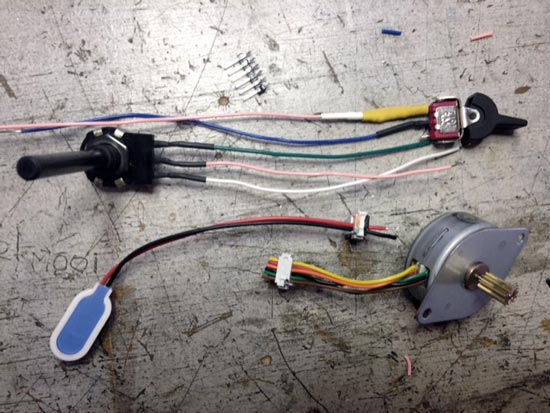
While I was milling I prepared all my components because not all of them will be surface mounted. I took care to insulate wires with shrink tubes (cool stuff!) after soldering wires to legs. And checked out how 6pin (2x3) connectors and the 4pin connectors translate if you press a wire into them. I did this in a similar way to the 6 pin rainbow wire above. Then I marked the orientation on the connector as well because it's really easy to flip it and connect it the wrong way around. To be extra safe I added a schottky diode to protect my circuit because I'm only human and known to make mistakes like everyone else ;).
I also had to measure how the button works exactly. I'm using it as an on/off switch and measured when it closed the circuit and when it opened to know where to put which wire. The third wire I'm not using I left it there and attached it to the unconnected third throughole of the footprint.
I tried burning the bootloader but my ISP refused service again so I did it with Emma's. I can then use it to program it, just not to burn the bootloader to 20mHz.
The first simple motor sketch I uploaded didn't start the engine, so I had to look for some bugs. Emma showed me how to check the voltages across the board and there was 9V on the power traces, and 5V on the microcontroller, the power out of the regulator to the VCC net. So that should be in order. Also, the computer could see the board and upload stuff to it.
Terminal check whether Mac can see the board: run avrdude -c usbtiny -p t44 (change t44 to something else if necessary). If it can see it it will say: "avrdude: AVR device initialized and ready to accept instructions"
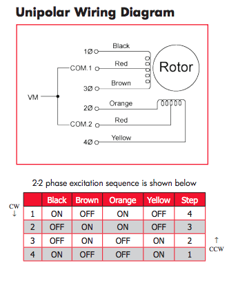
I realised quickly that I didn't connect the wires correctly to the 6pin Motor header. I didn't read the data sheet of my part correctly. I need to control the two coils with a pair of wires (Black&Brown, and Orange&Yellow), Red and green are power. This makes it very specific how they should be wired. And apparently our motor has different color scheme than Neil ;). So I cut off my header and rewired them. And then it worked! The wiring diagram in the datasheet also tells me how to activate the motor with the code
All I had to do then to run a first on/off test based on the one I found here on the Arduino website. Again I made the translations with this translation table:
Wellllllll i came in today and connected everything back up: no 5V on the microcontroller. The regulator is busted. We are assuming that it busts when the battery and the supply coming from the ISP are connected at the same time. Hmmmm. When I replaced it everything was working again. It even works when I just power it with the ISP.
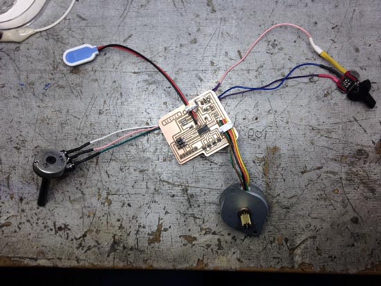
So far I haven't been able to set up a serial communication to find out what values the potmeter is giving so I'm still a bit in the dark as to how much it influences the speed exactly. But here's the working circuit, the quality is not great but you can see how the speed of the movement changes as I turn the potmeter.
I tried to read the potmeter values with the multimeter but can't seem to get a correct reading, but I woke up today and thought: I can read the resistance with the multimeter when it's not powered! I've been trying to measure it when the circuit was powered, maybe that's the problem. And it was. I measured the min and max Ohm value on the pot and the range is 2 Ohm to ~900 kOhm
I noticed that the motor is working when I power it with 5V from the computer but it the potmeter gets crazy hot. I'll try to avoid it.
All nice that it works now. BUT! I don't want random to and fro movements, I want a seemingly continuous motion in one direction with the speed controlled by the potmeter.
I used Kelly Zona's documentation to understand the code a bit better and figure out how to do other stuff with it. She uses an Arduino stepper library to control the motor. Getting to understand this a little bit it became a lot easier to do the motor what I want. In the code I had to change a few things that I looked up in the data sheet, like how many steps are in one rotation. I mapped the max range of the potmeter resistance to a speed range I like looking at. And now it works! Winnnnn!!!
where to add a diode
where to add a switch
Read up on operating voltage of devices. Eg 1.8-5.5V for Attiny24V/44V/48V. 2.7V-5.5V for the ATtiny24/44/48. You can't just put more Voltage on a device, it wil break. Instead, use a regulator. We have two kinds: 3.3V and 5V regulators. It has: In, Input, Out, Output and GND. Input is the power supply (the additional power source). Output will be 3.3V of 5V. Look at the typical application circuit. capacitor at OUT is most important. The capacitor at the IN (power supply) is the one that's always in the attiny circuit. If you connect it with the wrong orientation you will break your board for sure. You can add a diode on the VCC to protect circuit.
When using power supplies: make a distinction in your circuit between VCC and POWER! VCC as OUT coming from regulator. POWER is the net between power supply and IN of regulator. Know to what power net you need to connect what.
You can use a laptop adapter as supply. Look at output and current to see if it fits your application. Cut the wire: two cables inside, red is power, black is GND.
RGB LED has four pins, 3 colors and a shared pin, either shared anode (shared +) or shared cathode (shared -). Shared + Anode: put resistors between LEDs and GND. Shared - Cathode: put resistors between VCC and LEDs. Blue LED needs less current: 1kOhm, so smaller resistor (499) than the others (1k, they need 500 Ohm).
Examples use Charlieplexing concept. Use arrays to control LEDs, see Emma's slides. The way to configure them in Arduino, use three modes:
Using a regulator
Using a MOSFET, this is a very strong transistor that can afford a lot of current. In this case you use it like a switch, controlled by the IC. Turn it on by applying Voltage from the IC, put it HIGH.
They work in opposite ways. P-channel sources current: apply LOW to have current, apply HIGH = no current. The N-channel MOSFET sinks current to GND. The N-channel is a lot easier to use, so choose that one if you can.
Has N-channels and P-channel MOSFETS inside, we have one with driver that generates 7V all by itself > the charge pump. You use an H-bridge transistor to amplify current in two directions: as N-Channel (sink current to GND) and as P-channel (sourcing current).
H-bridge: two pins supply: POWER as well as VCC. There's two inputs, and two outputs, a GND (and another pin, leave it floating).
You can control more than one DC motor with one IC: use the same motor, with the same current supply. Use two H-bridges that share the same IN1 and IN2 pin coming from the IC.
No continuous motion, it works in a range of rotation. But you have control over position with feedback. It needs regulated Voltage. Put a bigger capacitor eg. 22mF between VCC and GND. Because it pulls a lot of current in short time. Differs per output device!
We have unipolar steppers. Uses a different method of motorization. You have control over position. You use a MOSFET for this, not an H-bridge. Use a 6-pin header. Two pins to POWER. Four pins to an N-MOSFET, each MOSFET is connected to IC via gate
Check the current on the circuit! ~1mA = ok. ~10mA is a shock.....~100mA you could die. It's not about Voltage, the current is what makes it dangerous, even under low Voltages.
