- Logged in as: fablabtaipei (fablabtaipei)
- Recent changes
- Media Manager
- Sitemap
- Admin
- User page
- Update Profile
- Logout
User Tools
- Logged in as: fablabtaipei (fablabtaipei)
- Admin
- User page
- Update Profile
- Logout
Site Tools
Table of Contents
Project Development
Copyright Claim
Affordable Distantly Attending Machine by I-Feng Lin is licensed under a Creative Commons Attribution-ShareAlike 4.0 International License. Based on a work at http://fabacademy.org/archives/2015/as/students/lin.i-feng/project_development.html.

Implication and Application
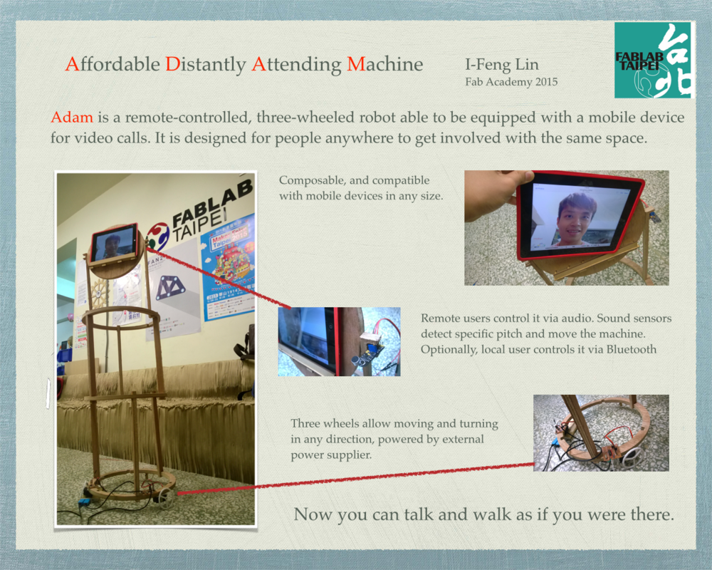
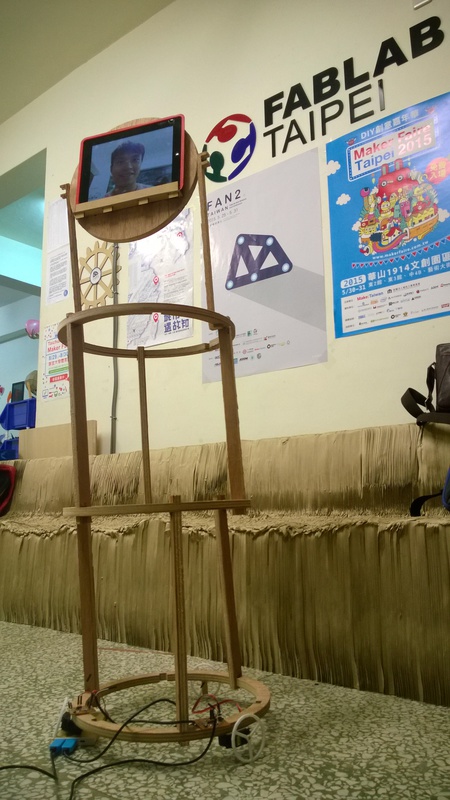
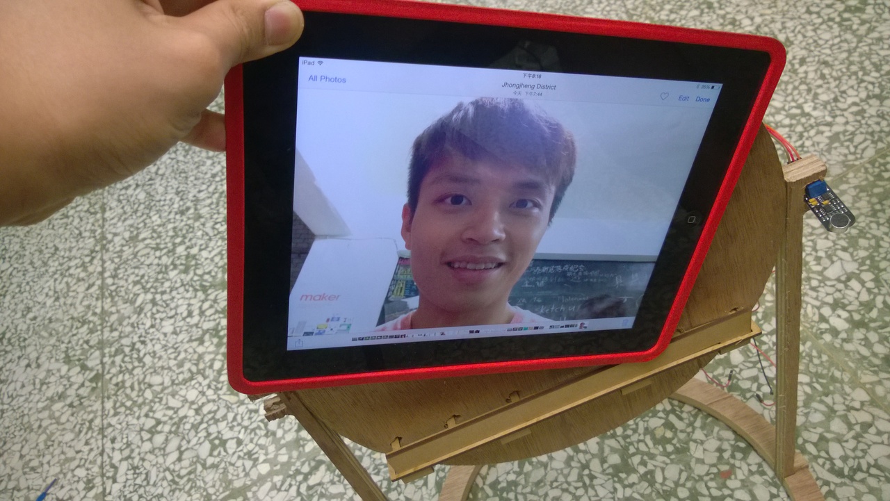
Adam (affordable distantly-attending machine) is a remote-controlled, three-wheeled machine able to be equipped with a mobile device for video calls. It is designed for people anywhere to get involved with the same space in scenarios like conferences, factories, and fab labs.
Computer-aided Design
I used the following software for my designs. You may also download the files.
Adobe Illustrator
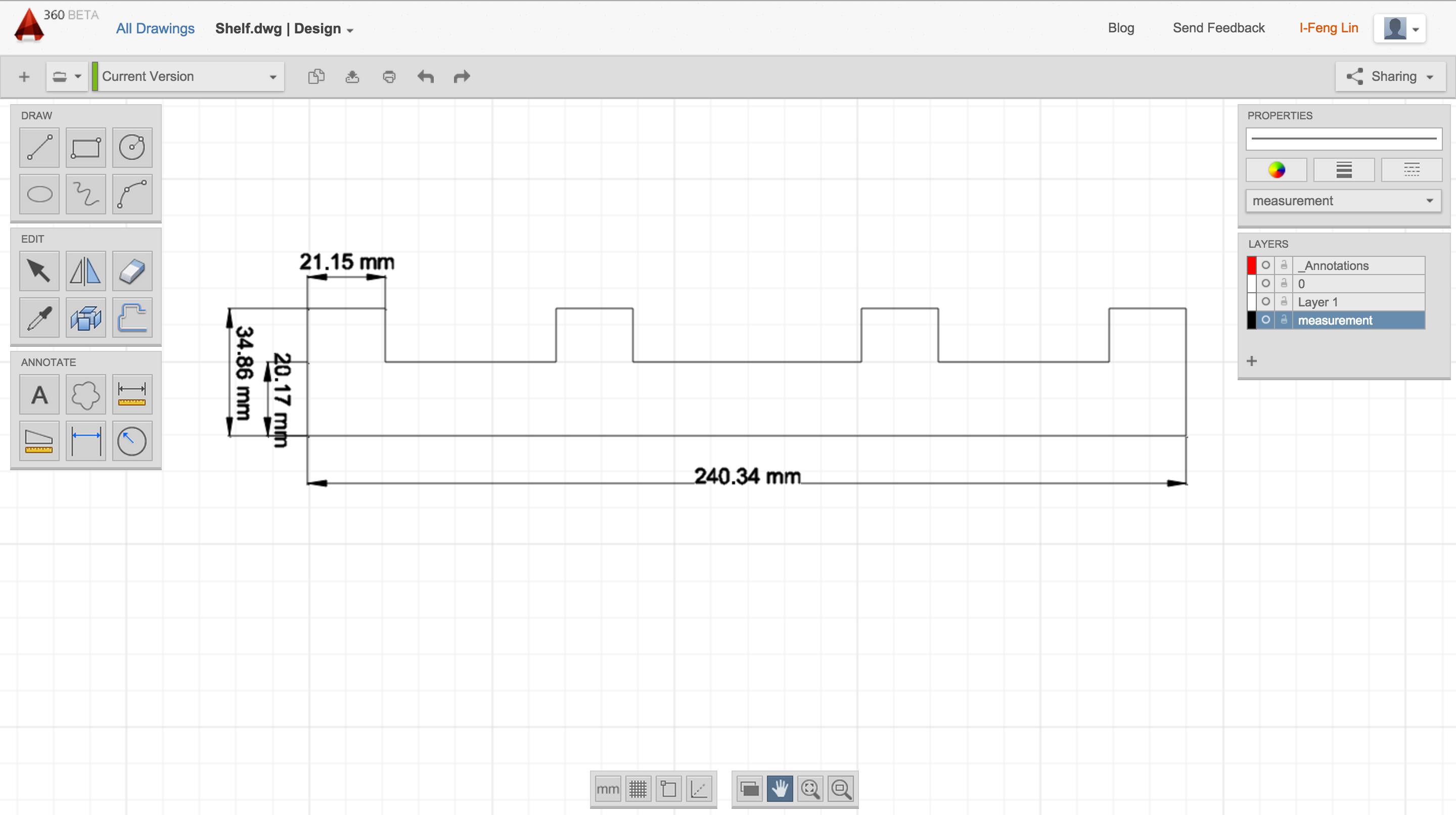
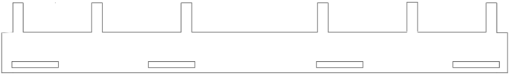
AutoCAD 360
- Raft draft: shelf.dwg
- Body components: bars.dwg, circle.dwg
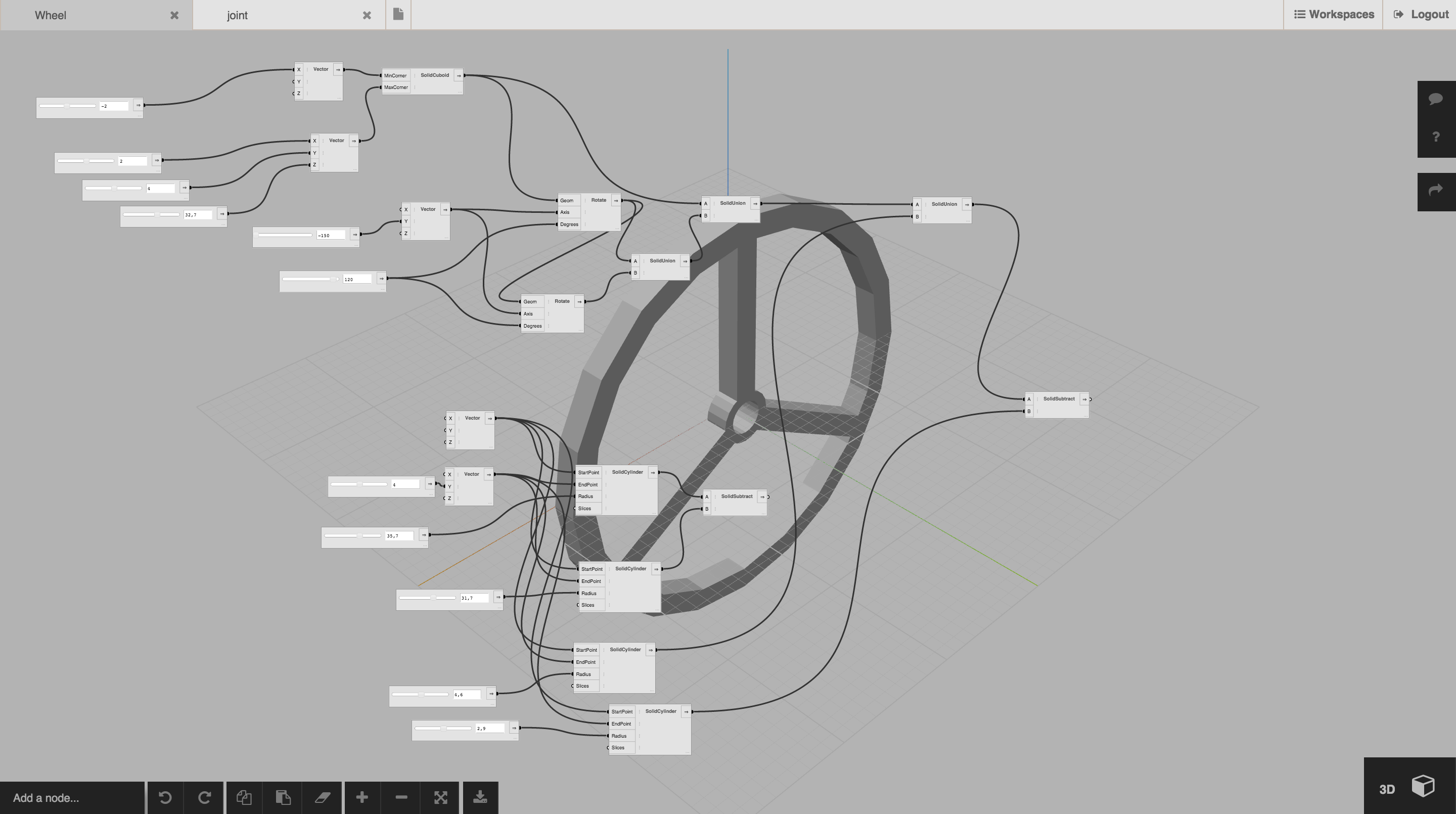
Flood Editor
- Wheels: bubbles version, Mercedes version
- Joint to attach bubble wheels and SG90 motor: joint.stl
Computer-controlled Cutting
Laser Cutter
I used laser cuter for cutting the fence.ai and shelf.ai for equipting a mobile device on Adam.

Vinyl Cutter
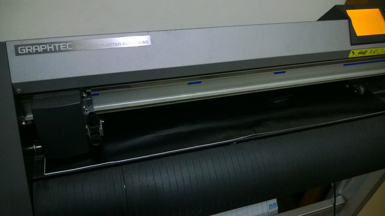
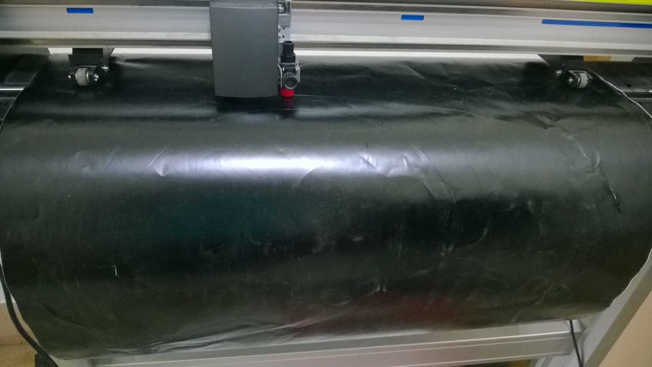
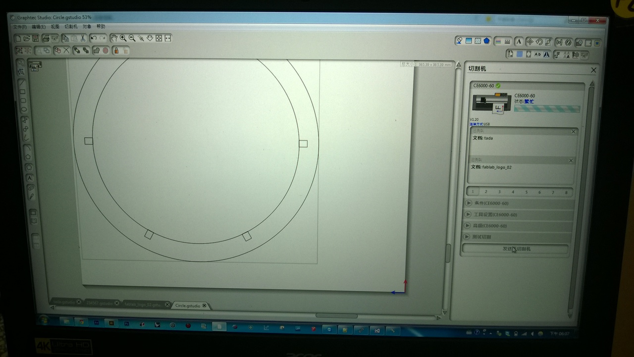
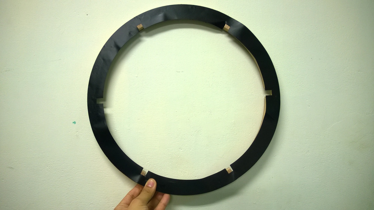
I used Graphtec Cutting Plotter CE6000-60 for cutting the skin layers of the circle.dxf of Adam. The software was Graphtec Studio and the default setting applied well. One thing to note was that the blade of vinyl cutter so very thin to ignore the width. However, large CNC machining used blades from 0.1 mm to several mm so the width on the model cannot be ignored. The design would need some modification.
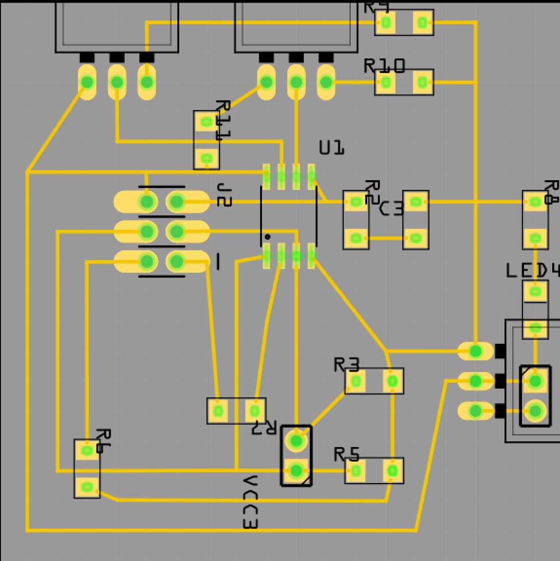
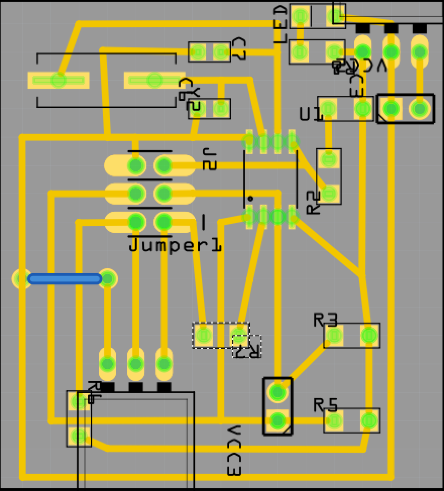
Electronics Design
I used Frizting to draw the boards. I had three design:
Sensor Board
This board can have two sensors with one output pin, and I2C/SoftwareSerial communication. week11_i2c_input.fzz
Bluetooth Board
This board can have one sensor with two output pins. and I2C/SoftwareSerial communication. 4pins_i2c_input.fzz

Motor Board
This board can have one output device with one output pin, one 20 Mhz oscillator, and I2C/SoftwareSerial communication. servo_i2c_output.fzz
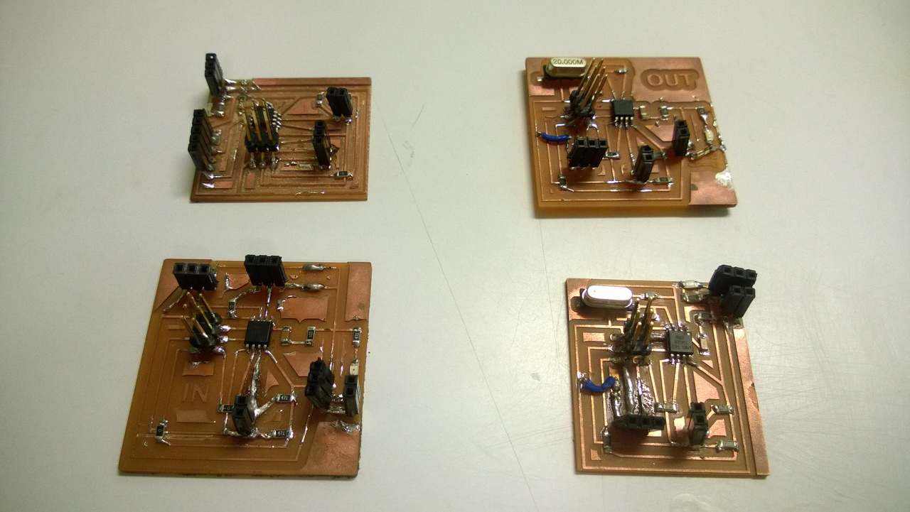
Electronics Production
I used Roland MDX-20 with 1/64 and 1/32 mm blades to make all my boards.
3D Scanning and Printing
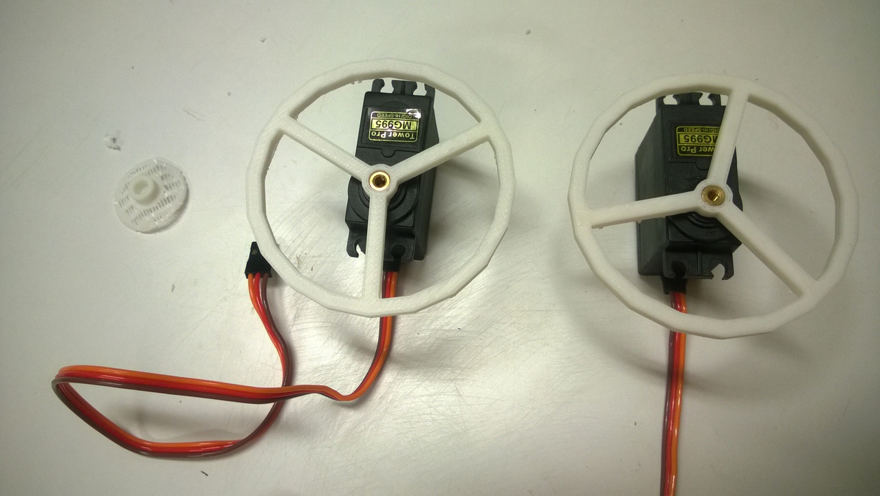
I used 3d printer for wheel production. At first I used MG90 motor and made wheels for them.
(Those I called bubbles version.)
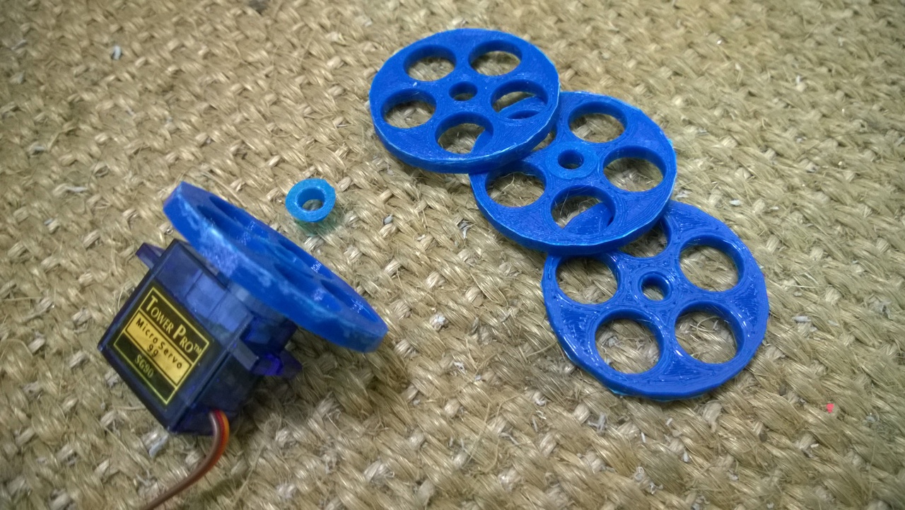 Later I realized the wheels were too small for Adam and they did not look that nice, so I made Mercedes version for MG995 motor.
Embedded Programming
I wrote three pieces of code. One for sound frequency detector board, another for bluetooth board, and the other for server motors board.
Code for sound frequency detector board
It takes inputs from two frequency detectors and sends signals to motor boards:
#include <SoftwareSerial.h>
#define FORWARD (byte)1
#define BACKWARD (byte)2
#define OUT_THRESHOLD 700 // the silence value is about 590 - 610

SoftwareSerial mySerial0(1, 0); // RX, TX (RX is not used)
SoftwareSerial mySerial2(4, 2); // RX, TX (RX is not used)
int sensorPin_A2 = 2;    //Microphone Sensor Pin on analog 2
int sensorPin_A3 = 3;    //Microphone Sensor Pin on analog 3
int sensorValue_A2 = 0;
int sensorValue_A3 = 0;
void setup() {
  //TinyWireM.begin(); // join i2c bus (address optional for master)
//  SoftwareSerial.begin(9600);  // start serial for output
//  SoftwareSerial.print("Neil, we are recording.");         // print the character
  mySerial0.begin(4800);
  mySerial2.begin(4800);
}
void loop() {
  char buff[100];
  // read the value from the sensor:
  sensorValue_A2 = analogRead(sensorPin_A2);
  sensorValue_A3 = analogRead(sensorPin_A3);
  if (sensorValue_A2 < OUT_THRESHOLD && sensorValue_A3 < OUT_THRESHOLD){
    // when receive detect frequency, turn around.
      mySerial0.write(BACKWARD);
      mySerial2.write(FORWARD);
      delay(1000);
  } else if (sensorValue_A2 < OUT_THRESHOLD ) {
    // when receive detect frequncy A2, move forward
      mySerial0.write(FORWARD);
      mySerial2.write(FORWARD);
      delay(1000);
  } else if (sensorValue_A3 < OUT_THRESHOLD ) {
    // when receive detect frequncy A3, move backward
      mySerial0.write(BACKWARD);
      mySerial2.write(BACKWARD);
      delay(1000);
  }
}
Code for bluetooth board
It takes inputs from bluetooth module and sends signals to motor boards:
#include  <SoftwareSerial.h>
#define FORWARD (byte)1
#define BACKWARD (byte)2

SoftwareSerial BTSerial(4, 3); // RX, TX
SoftwareSerial mySerial0(10, 0); // RX, TX (RX is not used)
SoftwareSerial mySerial2(12, 2); // RX, TX (RX is not used)
char inChar;
void setup() {
  BTSerial.begin(38400);
  mySerial0.begin(4800);
  mySerial2.begin(4800);
}
void loop() {
   // Keep reading from HC-05 and send to Arduino Serial Monitor
  while (BTSerial.available()) {
    // get the new byte:
    inChar = (char)BTSerial.read();
    if(inChar == '1') { // 0 and 1 has the same 7 high bits
      BTSerial.println('F');
      mySerial0.write(FORWARD);
      mySerial2.write(FORWARD);
    }
    else if (inChar == '2') {
      BTSerial.println('B');
      mySerial0.write(BACKWARD);
      mySerial2.write(BACKWARD);
    }
    else if (inChar == '3') {
      BTSerial.println('L');
      mySerial0.write(BACKWARD);
      mySerial2.write(FORWARD);
    }
    else if (inChar == '4') {
      BTSerial.println('R');
      mySerial0.write(FORWARD);
      mySerial2.write(BACKWARD);
    }
    else {
      BTSerial.write(inChar);
    }
  }
}
Code for servo motor board
It takes inputs two RX pins and controls one servo motor:
#include <SoftwareServo.h>
#include <SoftwareSerial.h>
#define MOTOR 1 // change this to assign left/right wheel
#define FLAG_FORWARD (byte)1
#define FLAG_BACKWARD (byte)2
#define DIRECTION_FORWARD MOTOR==1 ? (byte)0 : (byte)180
#define DIRECTION_BACKWARD MOTOR==1 ? (byte)180 : (byte)0
#define DIRECTION_LEFT MOTOR==1 ? (byte)0 : (byte)180
#define DIRECTION_RIGHT MOTOR==1 ? (byte)180 : (byte)0
#define DIRECTION_STOP (byte)90

SoftwareServo myservo;  // create servo object to control a servo
byte inByte = DIRECTION_STOP;
SoftwareSerial mySerial(2, 0); // RX, TX (TX is not used)
void setup() {
  myservo.attach(1);    // attaches the servo on pin 1 to the servo object
  motorMove(1000, DIRECTION_FORWARD); // say hello and test all instructions
  motorMove(1000, DIRECTION_BACKWARD);
  motorMove(1000, DIRECTION_LEFT);
  motorMove(1000, DIRECTION_RIGHT);
  mySerial.begin(4800);
}
void loop() {
  while (mySerial.available()) {
    inByte = (byte)mySerial.read();
    if (inByte == FLAG_FORWARD) {
      motorMove(1000, DIRECTION_FORWARD);
    }
    else if ( inByte == FLAG_BACKWARD ) {
      motorMove(1000, DIRECTION_BACKWARD);
    } else {
      turn(5);
    }
  }
}
void motorMove(int moveTime, byte moveDirection) {
  // move time in 10ms.
  int moveD=0;
  for(pos = 0; pos < moveTime ; pos++ )
  {
    moveD = moveDirection;
    myservo.write(moveDirection);
    delay(1);
    SoftwareServo::refresh();
  }
 }
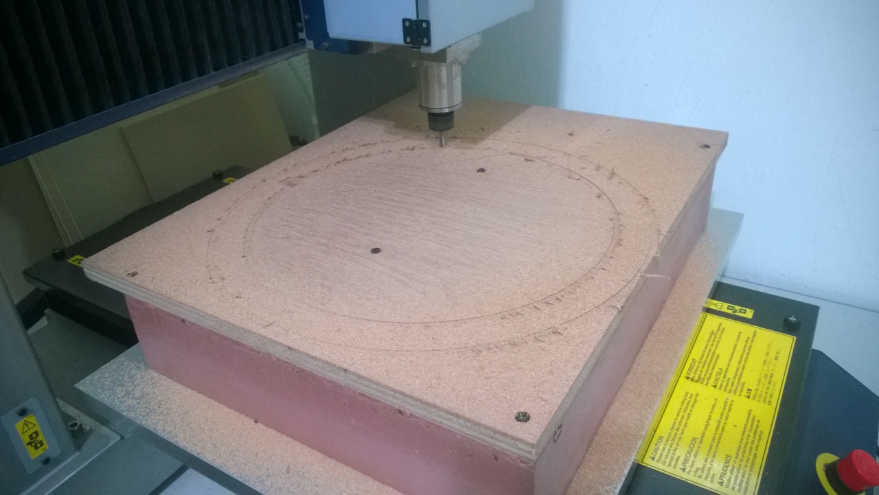
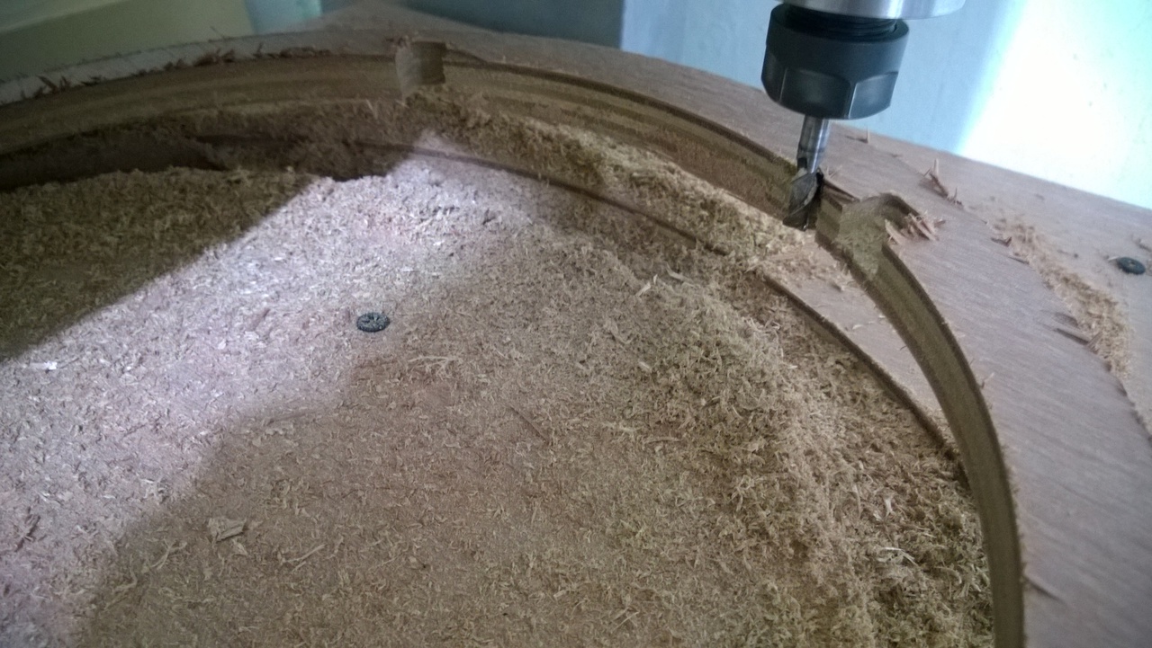
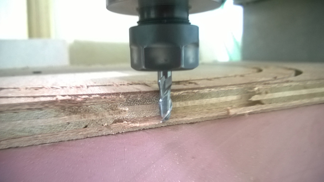
Computer-controlled Machining
I made a composable stand of Adam out of tool wood.
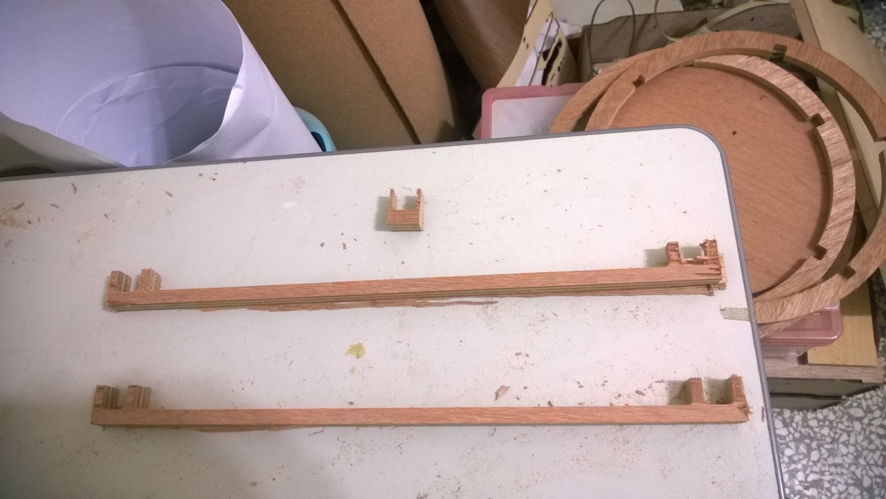
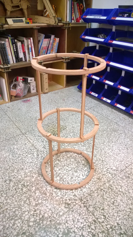 Check details at Computer-controlled Machining week.
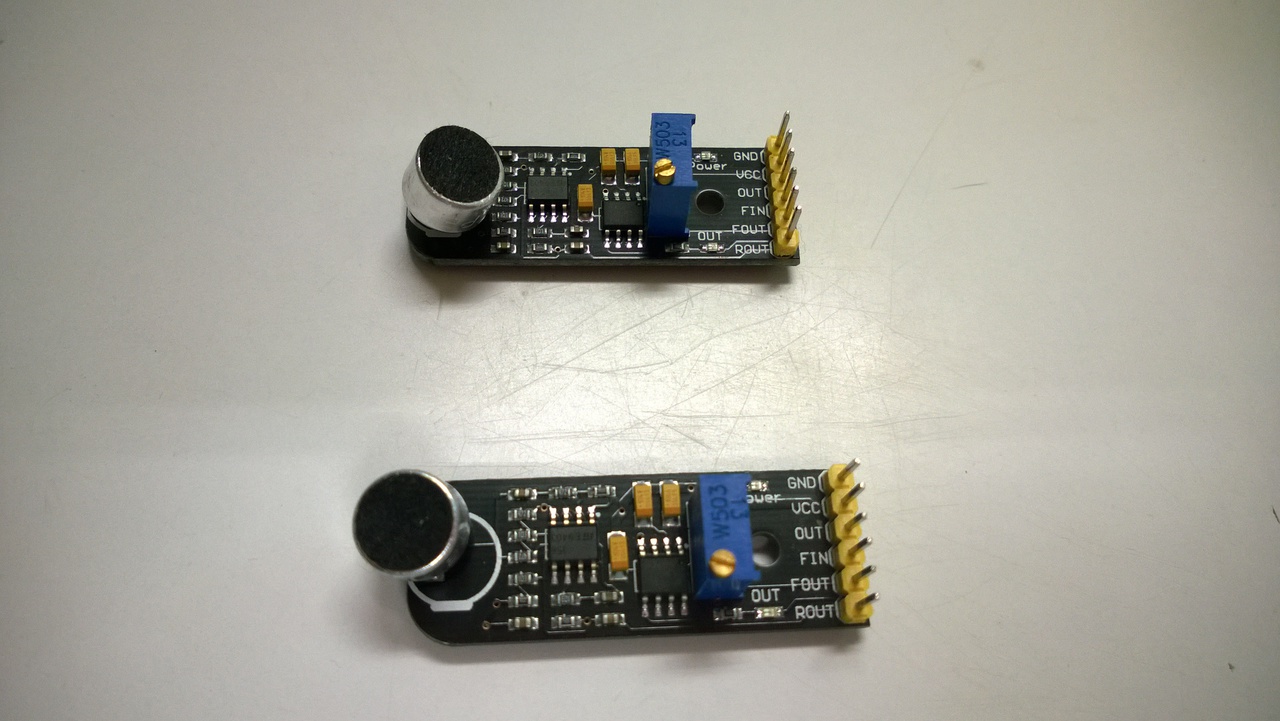
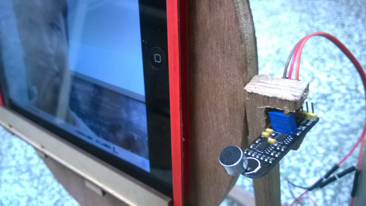
Input Devices
I purchased two sound frequency detector from AliExpress and I did not find anywhere else to get them. One is about 12 USD. It has there outputs: out, fout, and rout. In addition there is a fin pin. I used it only for its fout because I could not figure out what other outputs stood for. The behaviour of fout was that it sends values 590 - 610 at rest status and sends values 1 - 10 when it detects specific frequency. The frequency it detected was decided by the variable resistor on the chip and I tuned it to detect middle C and low G on both detector respectively.
Output Devices
Continous Rotation Servo Motor
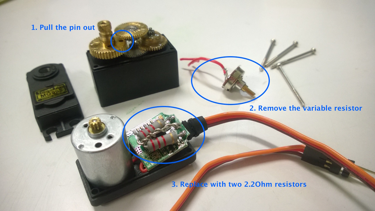
At first I used SG90, which was really cheap and accessible, but it was rather weak. Therefore I changed to MG-995.
Servo motor is designed for accurate positioning within a specific range, usually 180 degree, and not for continuous rotation. There are two mechanisms stop it from doing so. One is variable resistor, which changes its resistant with the position of gear and therefore tells its accurate position. The other is a small pin on one of the gears that stop them from moving over certain degree. I followed to a very helpful tutorial How to modify a servo motor for continuous rotation and made my motors continuously rotate in both directions. This picture with notes let you get an idea.
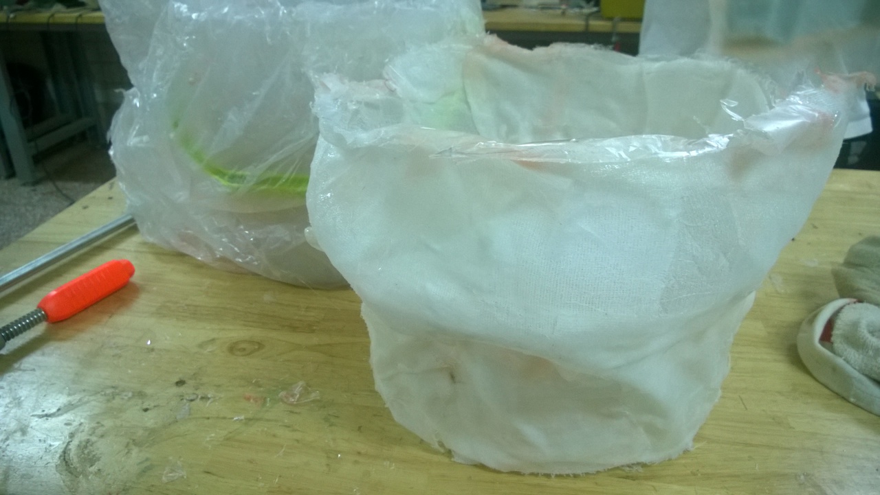
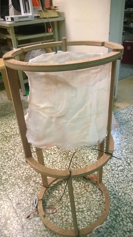
Composites
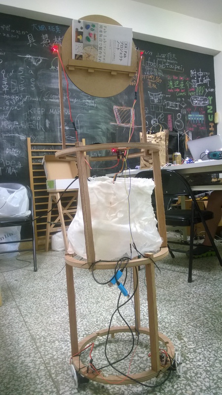
I made a inner shell for Adam so that it shakes less when moving.
 Check details at Composites week.
Networking and Communications
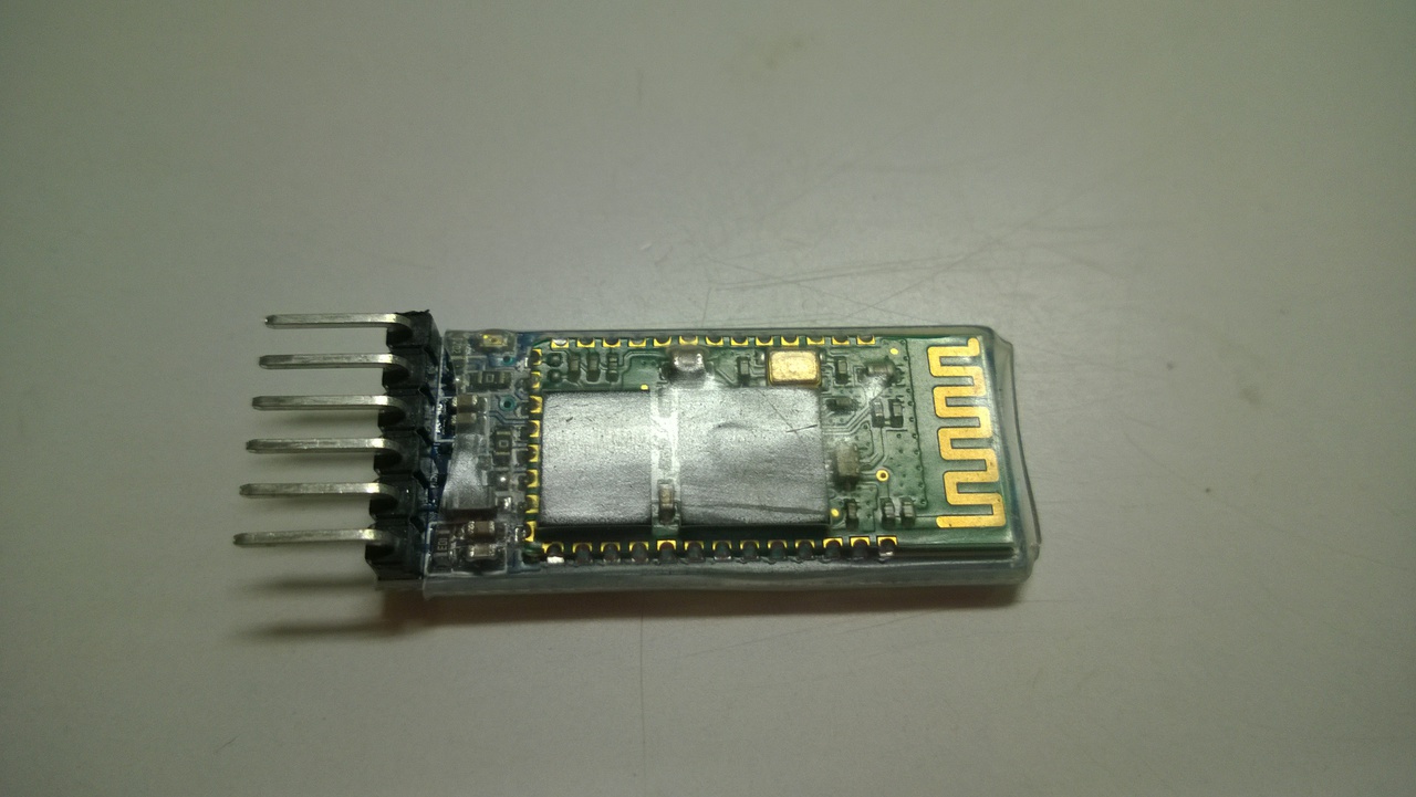
Bluetooth
I used bluetooth module HC-05 for Adam to receive commands directly from applications. First I used Arduino Uno to set its device name and UART rate. Upload the following code to Arduino.
/*
AUTHOR: Hazim Bitar (techbitar)
DATE: Aug 29, 2013
LICENSE: Public domain (use at your own risk)
CONTACT: techbitar at gmail dot com (techbitar.com)
*/
#include  <SoftwareSerial.h>
SoftwareSerial BTSerial(10, 11); // RX | TX
void setup() {
  pinMode(9, OUTPUT);  // this pin will pull the HC-05 pin 34 (key pin) HIGH to switch module to AT mode
  digitalWrite(9, HIGH);
  Serial.begin(9600);
  Serial.println("Enter AT commands:");
  BTSerial.begin(38400);  // HC-05 default speed in AT command more
}
void loop() {
  // Keep reading from HC-05 and send to Arduino Serial Monitor
  if (BTSerial.available())
    Serial.write(BTSerial.read());
  // Keep reading from Arduino Serial Monitor and send to HC-05
  if (Serial.available())
    BTSerial.write(Serial.read());
}
 Then wire HC-05 and Arduino. To enter AT mode, remove the power wire first and then plug it back in, so that the KEY pin was high before HC-05 is powered. Then use Arduino console to write the following commands into HC-05:
AT+NAME=Adam
AT+UART=38400,0,0
Then remove the wire on KEY pin and power it again. The device Adam can be discovered by another bluetooth device now.
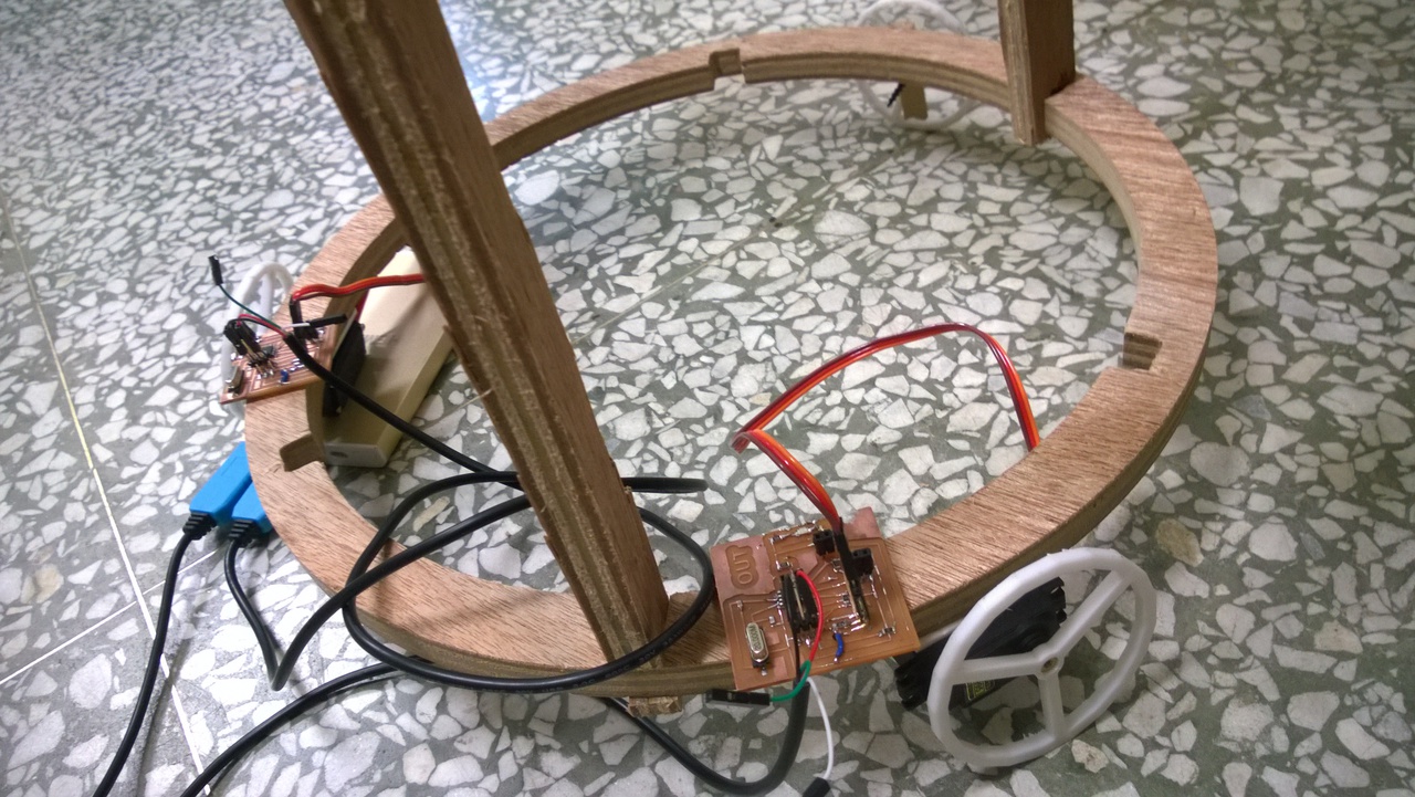
Connection Among Boards
Whenever the sensor board detected certain frequencies, tuned to be high E and high A here, it sent a signal to motor boards to rotate in either direction respectively. This video showed that it worked:
Show time
Adam did servo motor test in all directions when powered on in the video:
Eventually Adam was too heavy and crashed the wheels. Nonetheless this video showed that it worked when detecting high B. (the frequency of detection varied when the sound boards was wired to other components.)