
11 Output Devices
Assignment
- Add an output device to a microcontroller board you've designed and program it to do something.
Journey
Output with an LCD panel- This week I decided to play with an LCD panel. Here is a reference sheet to the Hitachi HD44780 LCD controller, which is often used to drive such panels.
- The normal way to drive this panel is to transfer data in parallel (8 or 4 bits) and with the requisite RS and E signals to clock the data into the display. This is quite simply done with the ATTiny64 using a minimum of 6 data I/O lines.
Here is the code for this: LCDoutput.ino - However, if we move towards the ATTiny45/85 we find that we do not have the necessary data lines. Hence, I decided to look into using a three/two or even one wire data line transfer. The principle is quiet simple by using an 8-bit shift register and clocking the data in one bit at a time.
The concept becomes more interesting by using a single data I/O port. This is done by using a capacitor to delay the second clock by the discharge and charge of a capacitor. - I started by building a circuit around the 74LS164 and using a two wire I/O port connection for the transfering of the data. One wire carries the data, while the other provides a clock signal.
- The principle is that you
- Read the data you want to display, and for each 8 bits,
- Serialise the output, adding the control bits RS and E
- Send it one bit at a time to the shift register by parallel outputting the bit and a generated clock signal
- At the end of the bit transfers, the shift register is ready to clock/transfer the nibble to the LCD panel in the normal way
I got the idea and the code from Two wire Interface for the LCD using a 74LS164 Shift register but did not have much success with the libraries or obtaining any output, so based on the raw code from Connect Arduino to LCD with a 74164 Shift Register I modified the code to display one line of text.
File:< Code for LCD with 74164(11_serial164.ino)
Prof. Neil interrupts...
During the weekly presentation Prof. Greshenfeld suggested using another processor to handle the communications. I couldn't figure out how to do that with another ATTiny45, but there is a commercial 1602 I2C board for just about the same price of an ATTiny84. I decided to use one of the 1602 I2C boards and it works exactly as described above. You have a microcontroller which receives the serial data and converts it to parallel before passing it to the LCD display.
The I2C/TWI LCD 1602 module allows the user to use I2C to communicate with a standard LCD module. I managed to get a few of these boards for only SG$2.50 (and includes a LCD panel as well) which seems so trivial to building one for use. Hence, I include the code here on how to display data using the module.
To enable this output device you would need:
- 1pc Hitachi LCD 44870 compaitble display
- 1pc I2C/TWI LCD 1602 module
- F. Malpartida's New Liquid Crystal library
We will also need to search for the I2C address, which is usually printed on the back of the 1602 panel (63). You can check my Networking page to see how this is done. (NB: I got interested in I2C after playing with the LCD modules!). Install the library, and we're done. The code is so simple and elegant that I do not see any purpose in using the 6 wire interface to the LCDs any more!
// Controlling a I2C 1602 LCD enabled panel

#include <Wire.h>
#include <LCD.h>                  // arduino libraries
#include <LiquidCrystal_I2C.h>    // F Malparida's library

const int I2CADDR = 63;                 // address of the module

// Defines your LCD module, if pins are not the same
const int EN = 2;
const int RW = 1;
const int RS = 0;
const int D4 = 4;
const int D5 = 5;
const int D6 = 6;
const int D7 = 7;
const int BACKLIGHT = 3;      //ok

// define the display unit
LiquidCrystal_I2C lcd(I2CADDR, EN, RW, RS, D4, D5, D6, D7);

void setup(){
	lcd.begin(16,2);        // using a 16x2 display

	// do this only once
	lcd.clear();
	lcd.home();
	lcd.print("Hello world");
}

void loop(){
	// do nothing
}
How simple is that!
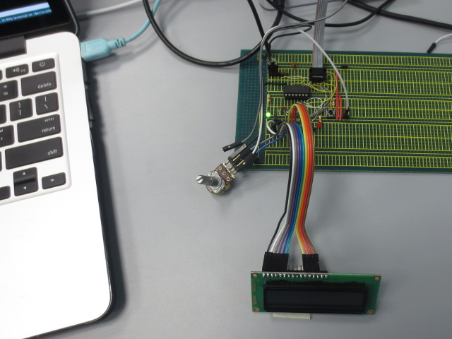
Normal 4-bit parallel data transfer to LCD
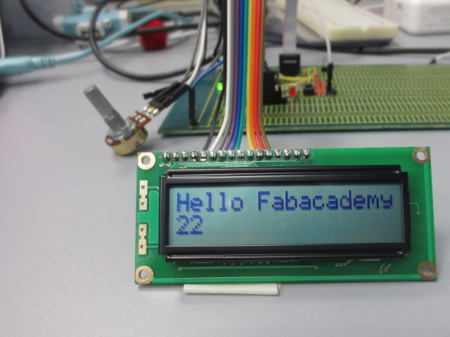
Sample output on a LCD panel
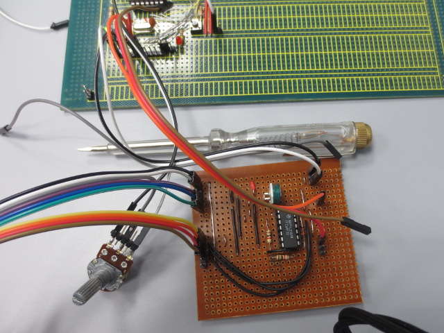
2 wire interface using 74LS164 shift register
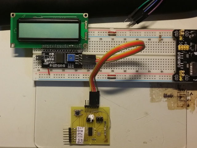
LCD with I2C interface for twin-wire transfer
Driving A Stepper Motor
A stepper motor allows the user to move the motor in a series of steps by sending appropriate signals to the interface. Although there are stepper motor libraries available, I thought that this might be a good opprutunity to try driving a uni-polar as well as a bi-polar motor. The program is similar but the interface for driving the motors are slightly different.
Uni-polar motor driver
The simplest way to identify a uni-polar motor is to count the number of wires emiting from the motor itself, usually 6 (4 for the motor coils, and 2 from a center tap of the coils in which you supply power). The normal and easiest way of connecting a bi-polar motor is to use a ULN2003A circuit which can be found in any of the sites. I happen to have a board available, from one of the discarded projects and put it to good use. You will need to supply Vbb (Vmotor, usually 6-12V depending on the motor) and the inputs to step the motor. The code essentially energises one of the coils in a sequence and thereby drives the motor. A good reference is Instructables: BYJ48 Stepper Motor.
In the code, we just need to keep track of the coil energised position and by just changing the sequence (increment/decrement) we can then move the motor around in the number of steps necessary
const int stepPos[] = {0x08,0xc0,0x4,0x6,0x2, 0x3,0x1,0x9};
int currPos = 0;

...
// Move forward numSteps at howfast msec delay between steps
//
void step_forward(int numSteps, int howfast){
  for (int i=0; i < numSteps; ++i){
    stepper(stepPos[currPos]);
    currPos = (currPos+1) % 8;
    delay(howfast);
  }
}
Code: Full-Step Stepper Motor Control (Schematic: 11_StepperMotorRaw.ino)
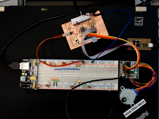
Bi-polar motor driver
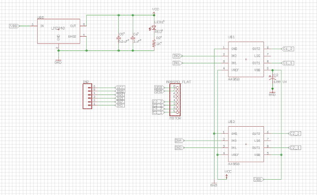
Bi-polar stepper motors differ in the sense that power is supplied directly to the coils. These motors have only 4 input wires (2 per coil) but are energised in a similar manner as the uni-polar motor. However, because of the high current draw, bi-polar motor drivers are usually driven using H-bridges. As we have the A4950, I decided to build a dual-output H-bridge board, providing 4 outputs (2 per H-bridge or coil). On the board I have also used a LM2940 to provide a local VCC supply. After fabrication, the board is connected to a bi-polar stepper motor (salvaged from a floppy disk drive) and the stepper motor program applied. It works!
Ref:
Commercial ULN2003 Uni-polar Stepper Motor Driver
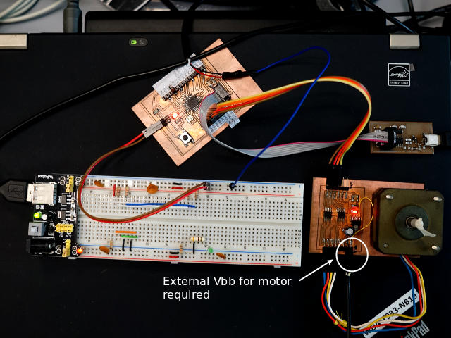
Dual H-bridge bi-polar stepper motor driver
Commercial ULN2003 Uni-polar Stepper Motor Driver
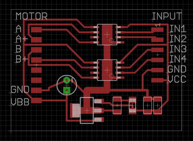
Dual H-bridge bi-polar stepper motor driver
Reflection
- Output can be obtained from the digital outputs of the microcontroller, however you need to match the pattern of the handshake signals.
- The LCD panel is one of the better ways of passing information but at the cost of 6 I/O lines (4 Data, 2 control). A better way is to use intelligent techniques like SPI or I2C.
- The cost of an I2C control board is far cheaper than designing one yourself with another controller. This would be the controller I would use for my final project as the control is simple and does not depend on the number of pins, however, a more powerful/memory CPU is required to store the software to run the data transfer.
- Stepper motors are relatively easy to drive. Its the designing of the circuits that are complex because of the heavy current drawn from the system. Track sizes have to be managed well, otherwise burn-outs are quite easy obtained.
References
- Hitachi HD44780 LCD controller
- Instructable - Hookup an LCD to an Arduino in 6 seconds with 3, not 6 pins
- text
Not being of a artistic mind, I have shamelessly borrowed this template (simpleStyle_8) from html5webtemplates, in recognition of a simple, cool and functional webpage design.