
13 Networking and Communications
Assignment
- Design and build a wired &/or wireless network connecting at least two processors
Adventures with RDuino
After looking at the Fabkit design and the Satshakit. I decided to try building one of these boards instead of using the ATTiny44. The main reasons for using the ATMega328p type boards are:
- direct use of the Arduino IDE and the rich libraries
- less mistakes in the selection of pins/ports
- less time in trying to think in AVR-C (I promise to do that after the course!!)
- a quicker transistion to the objective instead of tinkering around with the unfamiliar processor.
With those compelling reasons, you cannot overlook these two boards. Hence,
I sacrificed two days in trying out the FabKit and the Satshakit. I wasn't
really satisfied with the board layouts so, I tinkered with the design and
layout and drew my own circuitry.
Here are the boards:

FabKit v4.0

My versions of FabKit and Satshakit
Satshakit
Schematic
(13_Satshakit.sch),
Board (13_Satshakit.brd)
When I started using the boards for interfacing and experimentation, some pain points were evident:
- The pins for the ISP were not standard, you had to either build a customised header or keep track of the pin locations
- Timing operations with the 20MHz crystal were not compatible with the Arduino board and had to be adjusted using the workflow as highlighted in the Fabkit site
- Insufficient VCC/GND points for interfacing
- Horizontal pins instead of vertical ones for easier removal/insertion
Using the pain-points above, I decided to roll my own RDuino which would be compatible to an Arduino UNO and have its own ISP headers. I thought of adding my own FTDI header, but I have a number of Nokia CA-42 headers which are only 3 pins and are much cheaper and neater to use. Also the hardware Tx, Rx pins are next to each other so, not much is to be done there.
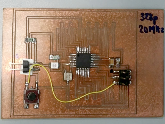
The features of the RDuino are:
- 16MHz Resonator
- ATMega328p, compatible with the Arduino UNO
- standard ISP header for easier programming
- Vertical pin output
- Inserted GND pins
- Power LED
After fabrication, you will need to burn the fuses for the ATMega328p, I suggest using the Arduino Uno default fuse settings
Low Fuse         0xFF
High Fuse        0xDE
Extended Fuse    0x05

avrdude -c usbtiny -p Atmega328p U lfuse:w:0xff:m -U hfuse:w:0xde:m -U efuse:w:0x05:m
The programming sequence is simple. Just write the program into the Arduino IDE, compile and check it. In the Tools section, select your programmer as USBTiny (assuming that you are using the FabISP) and the target board as Arduino Uno, and that's it!
I will be using the RDuino4 in most of my work as it is now so much more simpler to concentrate on the task at hand. In addition, I have used the laser printer to print out the pin names and labels. If you are rolling out your own, I would suggest using a Sans Serif 7pt with a line spacing of 1mm.
RDuinoV1 - first attempt, with libraries. Used 2mm headers instead of 2.54mm
RDunioV2 - corrected libraries, insufficient ground pins

RDunioV4 - current version used
Files: RDuinov4 (Schematic: 13_rduino_v4.sch,
Board 13_rduino_v4.brd)
![]()
I2C with the RDuino
- I2C requires only two lines SDA (Arduino: A4, ATM328: PC4) and SCL (Arduion: A5, ATM328: PC5), hence it is often called the two wire interface. You also need to provide the GND as reference, and of course Vcc should you also require to power the device as well
- I first decided to try the I2C with a LCD coupled with the I2C interface board. This gave me a chance to check out the code to identify I2C devices, the technique is as follows:
#include <Wire.h>                  // include the library
...
     Wire.begin();                 // initialise the I2C
     ...
     for (byte address=1; address < 127; ++address){
     Wire.beginTransmission(address);         // call device
     byte error = Wire.endTransmission();     // terminate
     if (error ==0){
         // device found at address
         ....
     }
     }
     delay(5000);
File: Seeking I2C addresses (13_i2cseekaddress.ino) - We also need to use the Serial library to output the result of the address back to the user so that it can be used in later projects. The LCD interface address was found to be 0x3F (63).
- Once we have the address, we can now program the I2C to send text messages to be output on the LCD.
    #include <Wire.h>
    #include <LiquidCrystal_I2C.h>      // F Malpartida's LCD library
    ....
    LiquidCrystal_I2C lcd(I2CADDR, EN, RW, RS, D4, D5, D6, D7);
    ...
    lcd.init();
    lcd.print("Hello, FabAcademy");     // Messages
    delay(1000);
    ...
File: Writing to an I2C LCD panel (13_i2c1602lcdtest.ino)
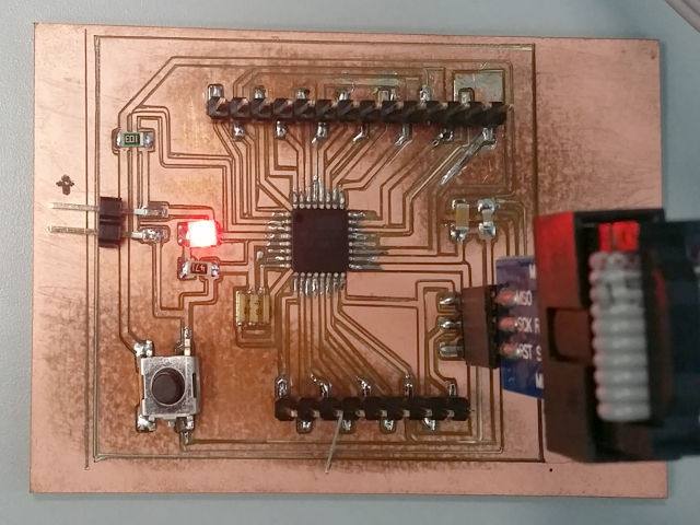
- Once we have confirmed that the I2C interface works, I used a 4-pin parallel cable (SCL,SDA,GND,VCC) to wire up two RDuino boards. You only need 3 pins (SCl, SDA and GND) if both boards are supplied separately. I decided to start with the ATMega328p processors first as the Wire.h library works and I do not have to deal with the restrictions of memory and differentiating pins. I was unsure of the transmission speeds so I used a 1.5K pullup resistor for the SDA and SCL lines. (Texas Instruments I2C Bus Pullup Resistor Calculation). The resistor values are estimated as we are not currently concerned about the speed of the bus.
- Each Slave is assigned an address (between 0 and 127). Each slave has a different address to differentiate themselves from each other. The slave listens on the bus and only responds when its address is called by the Master.
- The Master will send out the target Slave address. When the Slave responds, the Master will then send the The bridge board will send out the initial transmission using the node boards address, once the node board acknowledges, the master will send an integer to the node. The node upon reception will read the integer and flash its LED the requisite number of times.
- Master program will send an integer to the Slave. On receipt of the integer, the slave will turn on the respective LED. If a zero is received, the slave will turn off all LEDs.
- The following code is sent to the Master (i2cmaster.ino)
#include <Wire.h> const int SLAVE = 10; void setup(){ // start I2C as Master Wire.begin(); // use Serial to read the integer from the user Serial.begin(9600); Serial.print("Command: 1,2,3,0: "); } void loop(){ if (Serial.available()){ char c = Serial.read(); Serial.println(c); int data = 0xFF; switch(c){ case '0' : data = 0; break; case '1' : data = 1; break; case '2' : data = 2; break; case '3' : data = 3; break; } if (data != 0xFF){ Wire.beginTransmission(SLAVE); Wire.write(data); Wire.endTransmission(); } Serial.print("Command: 1,2,3,0: "); } } - When the slave (address 10) receives the correct transmission, it
will read the contents of the bus. If it receives 1, 2 or 3, it will
toggle the respective LED. If a 0 is reqeived, it will turn OFF all the
LEDs.
Code: 13_i2cslaveleds.ino#include <Wire.h> const int SLAVE = 10; const int LED0 = 11; // Use Pin PB3 const int LED1 = 12; // Use Pin PB4 const int LED2 = 13; // Use Pin PB5 // state variables int state0 = LOW; int state1 = LOW; int state2 = LOW; void setup(){ // initialise the LEDs pinMode(LED0, OUTPUT); pinMode(LED1, OUTPUT); pinMode(LED2, OUTPUT); // initially OFF digitalWrite(LED0, state0); digitalWrite(LED1, state1); digitalWrite(LED2, state2); Wire.begin(SLAVE); // start as Slave Wire.onReceive(event); // use interrupts, execute event Serial.begin(9600); // use serial to debug Serial.println("Ready"); } void loop(){ // do nothing Serial.print("."); // just to indicate that you're alive delay(2000); } // ISR to handle wire void event(int numBytes){ int num; while (1 < Wire.available()){ char c = Wire.read(); Serial.print("-"); Serial.print(c); Serial.print("-"); } int x = Wire.read(); // use only the last number Serial.println(x); if (x == 0) // turn off all LEDs state0 = state1 = state2 = LOW; else if (x == 1) // toggle LED0 state0 = !state0; else if (x == 2) // toggle LED1 state1 = !state1; else if (x == 3) // toggle LED2 state2 = !state2; // output results to LEDs digitalWrite(LED0, state0); digitalWrite(LED1, state1); digitalWrite(LED2, state2); }

Seeking an I2C device address

I2C LCD Test setup
I2C with ATTiny85
Spurred on with the success of the ATMega328 boards, I thought I might try using the ATTiny85 with I2C. On initial experimentations, I could not get the boards to communicate, even though I had reduced the complexity of the program and tests.
On further research, I found that I needed the TinyWire.h libraries to
make the ATTiny85 work.
Using the ATTiny85, I would have to calibrate the internal clock as well as
ensure the correct values of the pull-up resistor. The proper fuses should
also be programmed into the ATTiny85 as it was working on an internal clock,
8MHz, and a divide-by-8 clock to work at 1 MHz.
I decided to abandon this task for a later date as
I had already proven that the protocol works on the ATMega328p and was running
short on time. I would probably not use the Arduino IDE for this purpose too.

I2C ATtiny85 Master Schematic
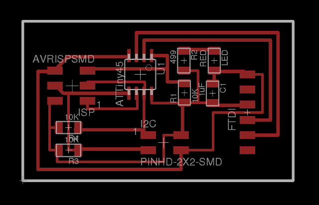
I2C ATtiny85 Master Layout

I2C ATtiny85 Master Board

I2C ATtiny85 slave Schematic

I2C ATtiny85 slave Layout
Vinyl cutting using Roland GS-24
- We took delivery of the Roland GS-24 on Friday this week and had high hopes on the development of the flexible PCB using vinly copper tape. We also took receipe of the copper tape from Barcelona Fab Labs.
The Roland GS-24 is a newer version of the CX-24 which was mentioned in the PCB development in FabLabs. However, upon initial cutting using the Copper Tape showed that at least another 5-8 hours is required to "tune" the machine to cut the PCBs. - The problems we saw during this process were
- Wrinkles in the copper tape rendering the tape unusable.
- Depth of the cut, which relied on the feel of the blade in the cutter, this is combined with the depth and force of the cutter which is sent on the control program.
- Scratching and pulling of the copper substrate, which is a cause of the speed of cut. It is similar to using a sharp cutting blade on newspaper but pulling the paper instead of cutting it.
- Weeding of the cut material is difficult as some of the copper is not cut through, plus we descovered that we require transfer tape (a less sticky version of celophane tape is required to transfer the cut PCB)
- It looks like we can only use traces around 20-24 mil for the boards, any thinner and I think isolation cuts will only work.
- In order to use the GS-24, you will need to load the Roland drivers which are only obtainable from the Roland's Internet site. The drivers are only written for Adobe Illustrator or Corel Draw.
- We loaded Corel Draw and the PNG image of the PCB. You will need now to use the Mouse R-Click to extract the outline for the printing. The outlines are arranged in order to produce an economy in printing and then sent to the plotter
- Plotting/cutting is fast, taking less than 15 minutes to cut the I2C bridge and node boards. However, weeding and extracting the cut is a problem and the lines less than 20 mil posed exceptional problems.
- I will produce a more detailed write-up in the future, as we then abandoned the tests for a lack of time.

Copper cut tape, bad settings
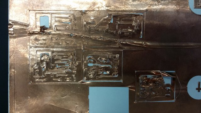
Uneven cuts and weeding
PCB Routing using Roland iModela
- We also took delivery of the V-shaped engraving tips for the iModela and straight away used the FabModules to create a simple PCB for testing. We found that the cut (using isolation cut) was good and now we have a means of creating PCBs, all-be-it, slow.
- Initial cuts were done usng the V-shaped 0.01 inch, 30 degree tool which proved to be ideal in the cutting process, the cutting values used were:
- Cutting parameters to be inserted here.
- With the cutter working, we made the txrx boards, the I2C boards and the level shifters for the 5-3.3V. I also managed to create a ATMega328P board based on the SashaKit, but with different layouts and a 6-pin header for ISP programming.
Reflection
- We managed to create PCBs on a small scale using the iModela, hopefully this would ramp up as we continue developing our own miller. We are thankful for the network of FabAcademy students and labs which provided a starting point for our milling values.
- I2C is a great way to handle board-to-board communiation provided the libraries can be compiled into the system. I2C can be used with or without Interrupts.
Not being of a artistic mind, I have shamelessly borrowed this template (simpleStyle_8) from html5webtemplates, in recognition of a simple, cool and functional webpage design.