
03 Computer-controlled Cutting
Assignment
- Design, Make, and document a press-fit construction kit (examples)
Journey
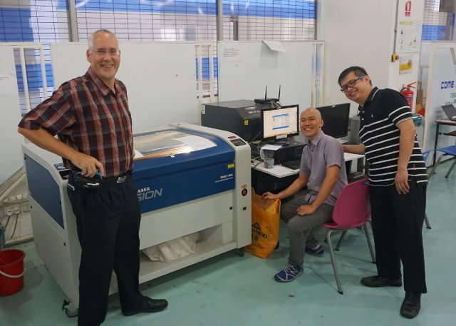 Epilog Fusion Laser with Jolygon, Ray, Edward
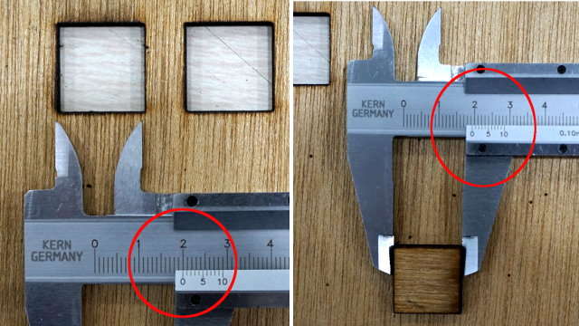 How to measure kerf in a cut
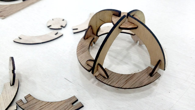
 Wood cut, gaps in fit
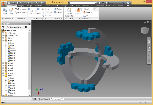 Assembly simulated using Inventor
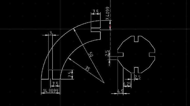
 QCad construction of sphere kit
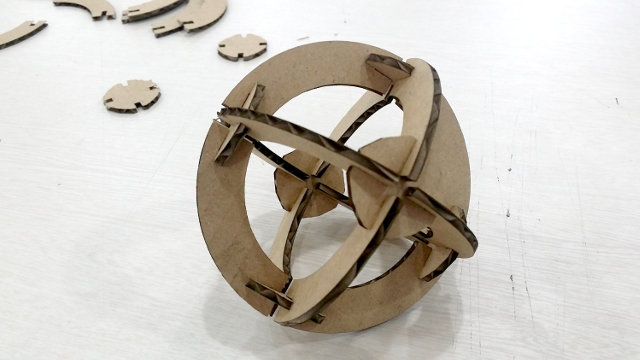
 Place-fit cut using 3mm corrugated fiberboard
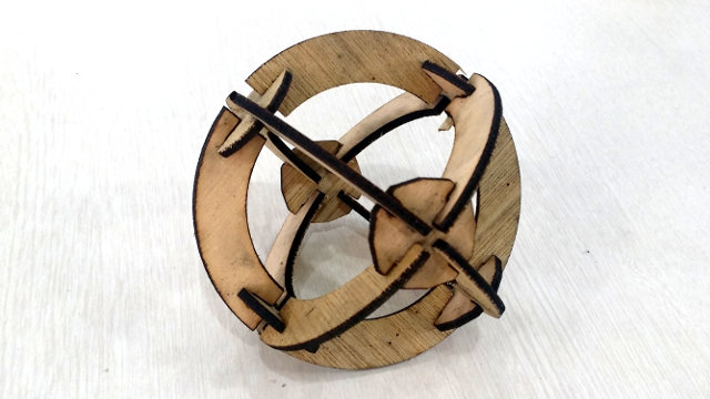 Constructed sphere, note the fit when kerf not considered
Files used:
03-place_fit_spheres.zip holds the .DXF files of the project.
03_place_cut_assembly.zip holds Inventor files for simulation of object
- Initial investigation - I researched some links and papers which were recommended by the site before deciding what to do. Here are some of the more interesting information I have discovered and should be read before attempting any cuts:
- Interference fit of Press-fit, the definition and mechanics behind the term.
- kerf the material left behind after the cut. Hence, design your cuts to include kerf if you want a tight fit. The following tutorial will explain more.
- Press-Fit Construction Tips - a tutorial on press-fit cuts and how to measure kerf for your laser.
- The press-fit example I have chosen is from Instructables - Press Fit Construction Kit which shows how to create a kit for making spheres using 2 parts. Instead of taking the PDF and files from the site, the parts were drawn using QCad from a sketch taking into consideration the sizes and parts basically from 2 concentric circles.
- The initial cuts were done on the Epilog-Fusion laser cutter using single wall 3mm corrugated fiberboard. There was no provision for kerf and the following cutting parameters used:
Speed: 80%, Power: 100%, Frequency: 80%
The values were adjusted so that a single pass would be sufficient, after some test cuts were made.
The cuts were very exact without much kerf, and the parts fitted well. - The second attempt was to cut the puzzle using 3mm scrap plywood which I had lying around in the lab. Here the kerf was much greater, as you can see from the photos. However, I did not take into consideration of the kerf and cut the parts from 2 different 3mm scraps. The fits were not tight and the different sheets gave different results.
Speed: 10%, Power: 100%, Frequency: 100%
Obviously a lot of fine tuning has to be done if we need to build a complete kit with wood. There was a lot of burn/ash from the cut.
Vinyl Cutting
Unfortunately, we did not take into account of the delivery dates and times of our vinly cutter (Roland CS-24) and had to suffer in silence. However, when it arrived the cutting was a disappointment, mainly because we did not calibrate the new cutter in time. You can see the results of this in c13 Networking - Vinly Cutter using the Roland GS-24.
We also have a very economical Brother Scan N Cut CM550, which is a desktop scanner and cutter. The device allows you to create, scan and cut your scans and is ideal for developing small stickers and other cuttings.
The process is quite simple,
- Draw your diagram or pattern using Inkscape and save as a .SVG file,
register and login to the Brother website and upload it. The site will convert your file to Brother's .FCM format for the CM550.
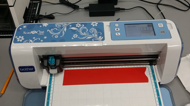
Alternatively, you could print out the design on paper and let the CM550 scan the pattern in. This is the simplest, but the scan may result is some inperfections on the cut - Load in the vinyl to be cut on the cutting mat, and scan the cutting mat in. The CM550 will automatically position your cutting on the tape
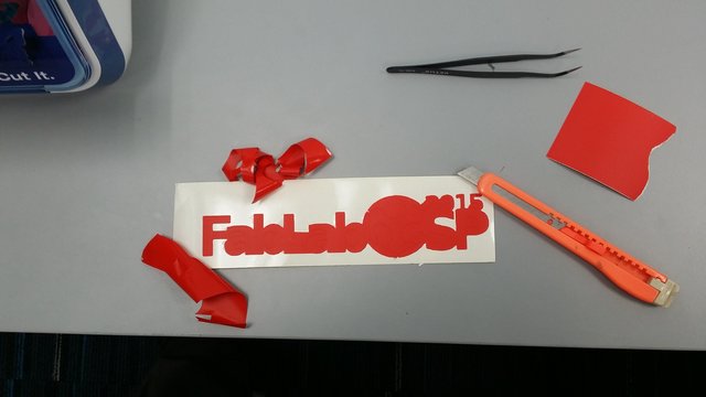
- After cut is completed, we then proceed to weed the cut. Weeding is to remove the extra, unwanted tape that surrounds the cut. You can weed with a pair of tweesers and a NT-cutter/blade. This takes some patience, and make sure that you use fresh vinly otherwise the glue on old vinyl may make removal difficult.
- We then use transfer tape (a type of celophane tape which is less sticky) to transfer the cut onto a transparent surface for application onto the target area.
- When applying on the target area, beware of air-bubbles which may spoil all your hard efforts!
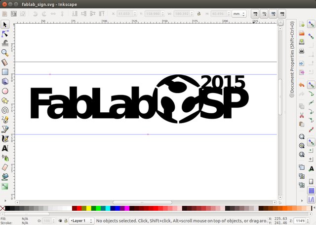
Cut design with Inscape
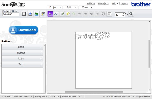
Conversion to native ,FCM from the Brother site
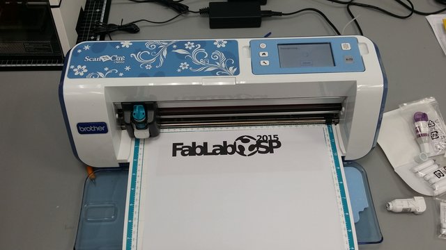
Alternatively, print and scan the design in
Scan the tape area for cutting
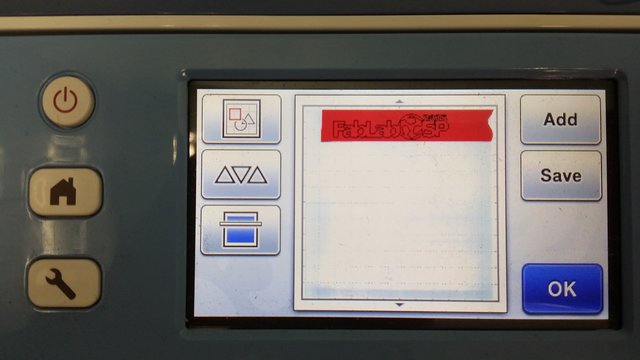
Aligning the cut with the tape
Weed out the unwanted tape
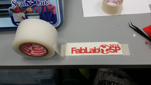
Use tranfer tape to transfer the cut
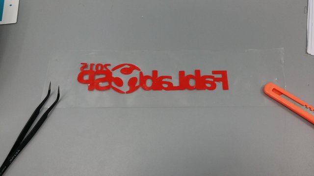
Transfered and ready to stick onto target
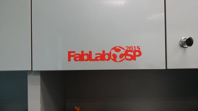
Fablab label stuck on my cupboard!
Reflection
- Very important to find the kerf of your laser cutting system. if you don't the parts just fall away.
- Very important to set the speed and power settings of the laser system correctly otherwise you might either get engravings (too fast, too weak) or burnt material (too powerful)
- Use the same type of material for each of the press-fit kits otherwise you might get different results, especially with plywood.
- Test cuts should be done to determine the kerf and optimum cutting power.
- The Laser cutters use Corel Draw which is definitely better than QCAD and simpler to use. However, it does accept DXF formats. You should also change all your line widths to hairline/vector before cutting.
- If the laser has been heavily used, you should consider getting the lens cleaned, which will improve the cutting capabilities.
References
- Box creation examples:
- Boxmaker - online press-fit kit with PDF output
- Press-fit ExamplesChampaign-Urbana Community Fab Lab project on boxes
- 4mm Plywood Crate - stackable plywood crates
- Img2CAD - Converts images to DXF, HPGL, etc
Not being of a artistic mind, I have shamelessly borrowed this template (simpleStyle_8) from html5webtemplates, in recognition of a simple, cool and functional webpage design.