Week 4
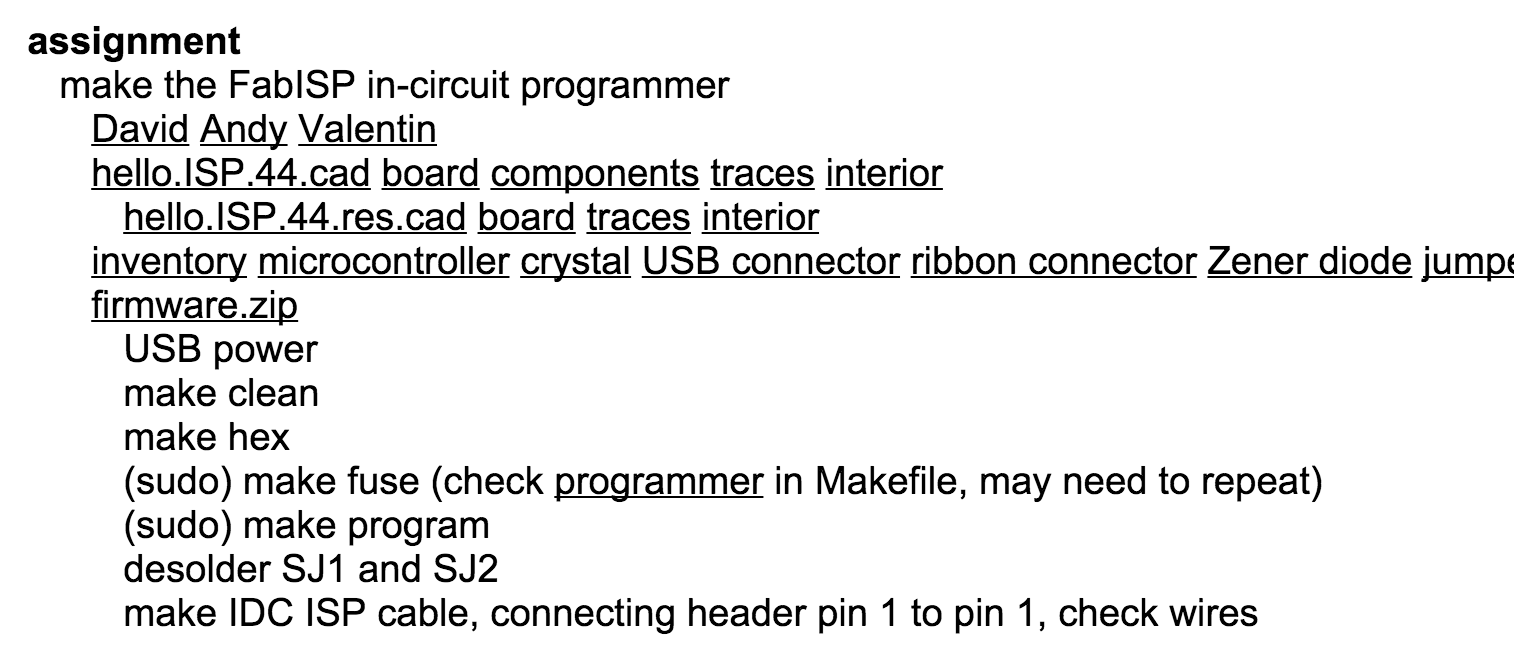
Assignment - Making the FabISP in-circuit programmer
First we started by learning about the what the ISP would be used for and how important it would be for the rest of the Diploma in terms of using it to programme other boards that we would create.
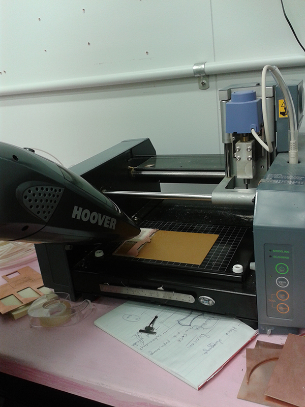
We used the MDX-20. It is a small CNC router which is a 3 axis machine and is really good for making small custom circuit boards, not so good for a large scale production where there could be hundreds or thousands of boards. The mill bits would wear out very fast and it isn't a very fast process. The machine is very accurate up to 0.05 mm, and has a very large pixel count, up to 8,000 pixels.
We used the Fab Lab PNG file named hello.44 ISP which gives two PNG files, one file is used to mill out the board and the other file is to cut the smaller board from the copper board.
The process of making the board
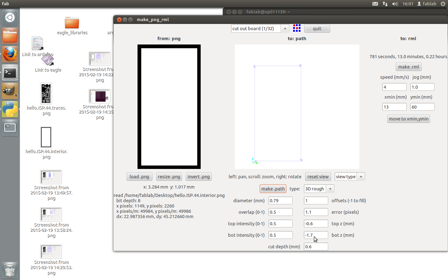
Type fab to open the Fab modules GUI and select the desired workflow. In our case Input image (.PNG) to Output MDX-20 (.RML).
First you need to make sure you have stuck the board down correctly to the base plate of the machine, with double sided sticky tape. Making sure that the tape is not over lapping and that you don't get sticky fingers all over it.
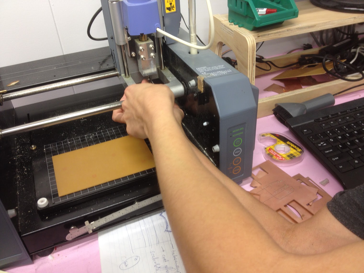
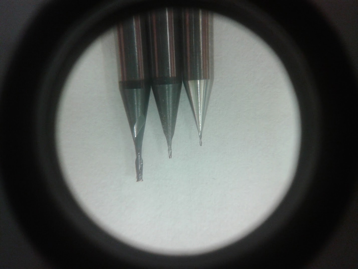
Next you need to make sure you have the correct drill bit in place, usually it will have the large 1/64 bit in because this is what most users would be cutting with. So we need to press view on the machine and change the mill piece over to a 1/32 bit. This is done by unscrewing the hex screw on the head of the machine, being very careful to not let the mill piece drop as it can be damaged very easily. So make sure you are using two hands!
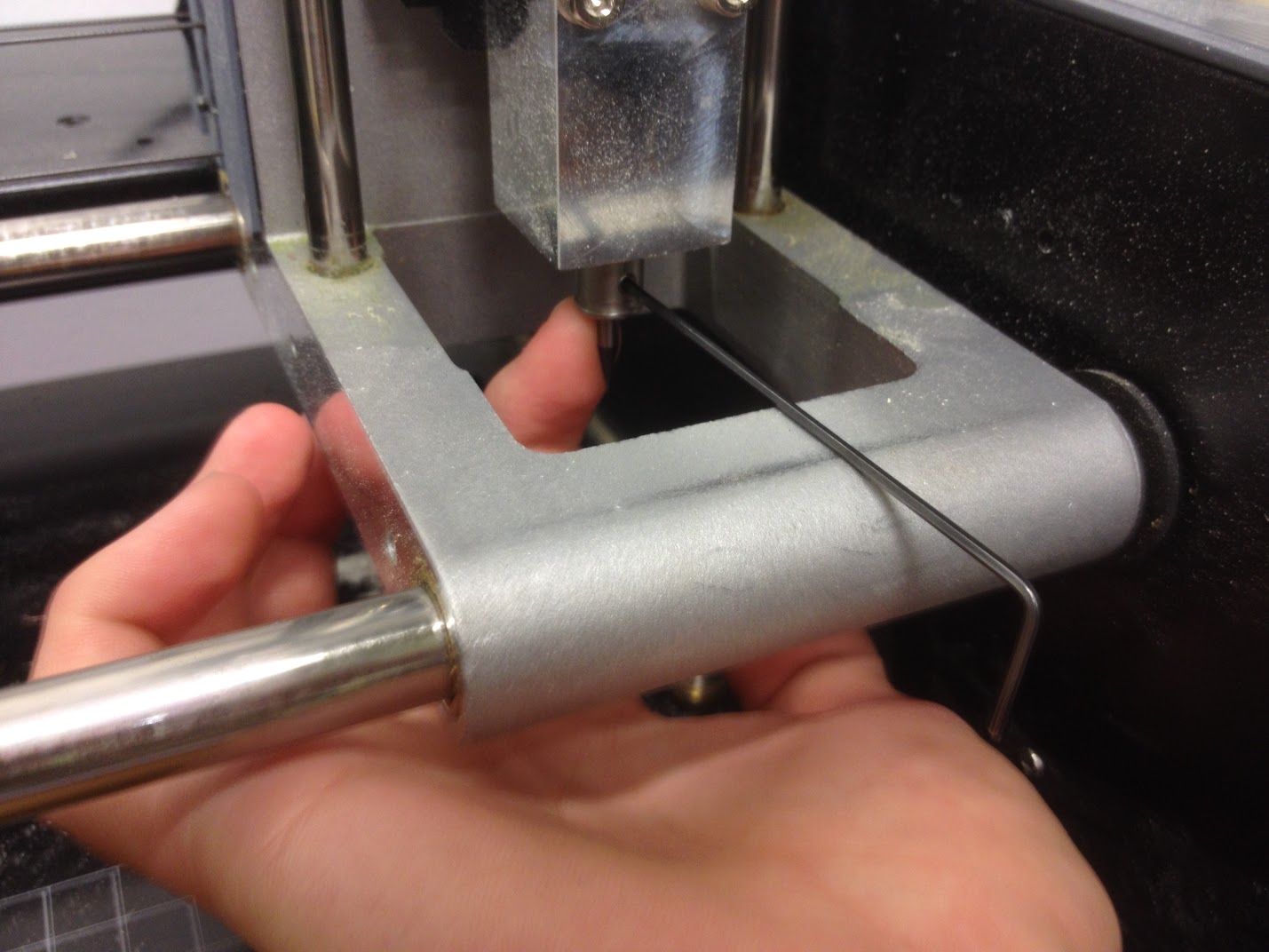
Once we have inserted the 1/32 mill bit we make sure that we have it far enough up in the head so when it comes down to measure the z axis it doesn't break it on the copper plate.
We then press view again to line the head back up with the corner of the copper plate, punching numbers in the open Fab Lab programme in the X and Y we can put in numbers to line the mill piece up with the corner on the bed where we have stuck our copper plate.
We know need to raise the Z axis enough so that it will cut through the mill board on its second cut with the other PNG file. We undo the hex bolt again and very carefully lower the mill piece onto the copper board and retighten the screw.
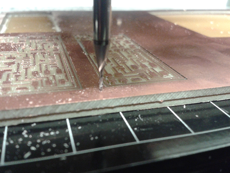
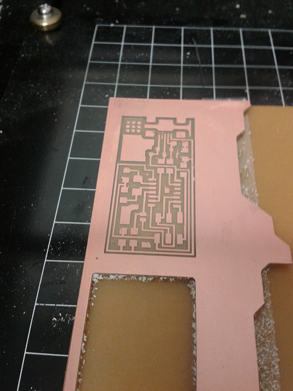
We then check the X and Y again and make sure we have selected the right file and file document settings. We can check the path of the mill to make sure it is going where we want and then we can hit send. The mill will start spinning and make a little hole where the origin was set, it will then processed to mill out the board which takes about 20mins.
Once the board is completed we used the vacuum cleaner to suck up the dust. We then need to redo the process of pressing view button and changing the mill bit to a large size: the 1/64 mill piece.
We then need to upload the other document (PNG file) which is going to cut the board out and make sure we have the same origin set, we can check this by where the mill bit is lowered down onto the copper it will be in the exact same spot.

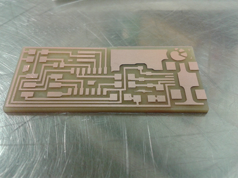
The PNG file will have a lot less of a path to take and should only take a couple of minutes. Once the board is cut we then try and pry it from the bed to make sure it has cut all the way through because if we pull the whole board off we might not be able to line it up correctly again in case we need to cut again.
Once we pull the board off we give it a visual inspection, and wipe it with a coarse nylon brush to remove excess dust. We then went and washed the board in warm water to remove natural oils from our hands.
Soldering time
Having done a bit of soldering I wasn't to daunted by this challenge.
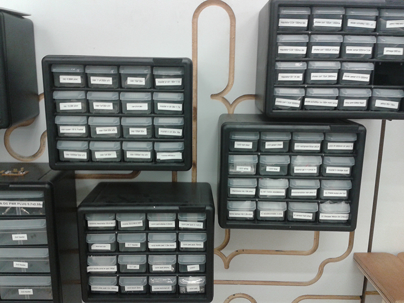
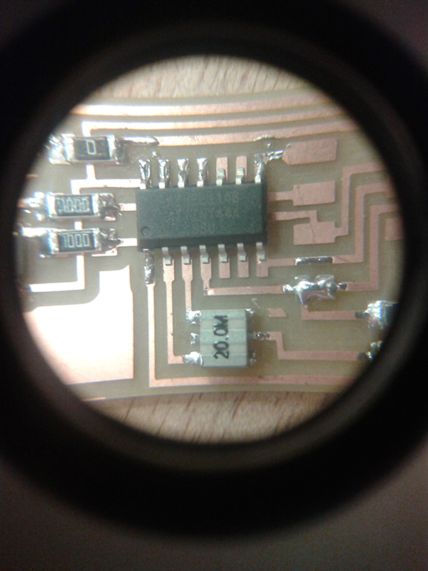
We looked at the diagram of the board and figured out all of the components We wrote this down on paper with a space of the side to place the object so we wouldn't get confused about which was which.
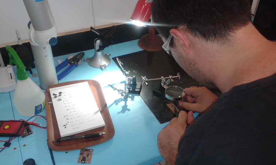
We then went over to the soldering stations and began soldering, I soldered at a temperature of 350 degrees. Sticking down the smaller pieces first and working my way out from the middle. I didn't find this too difficult but quite time consuming, having to use tweezers.
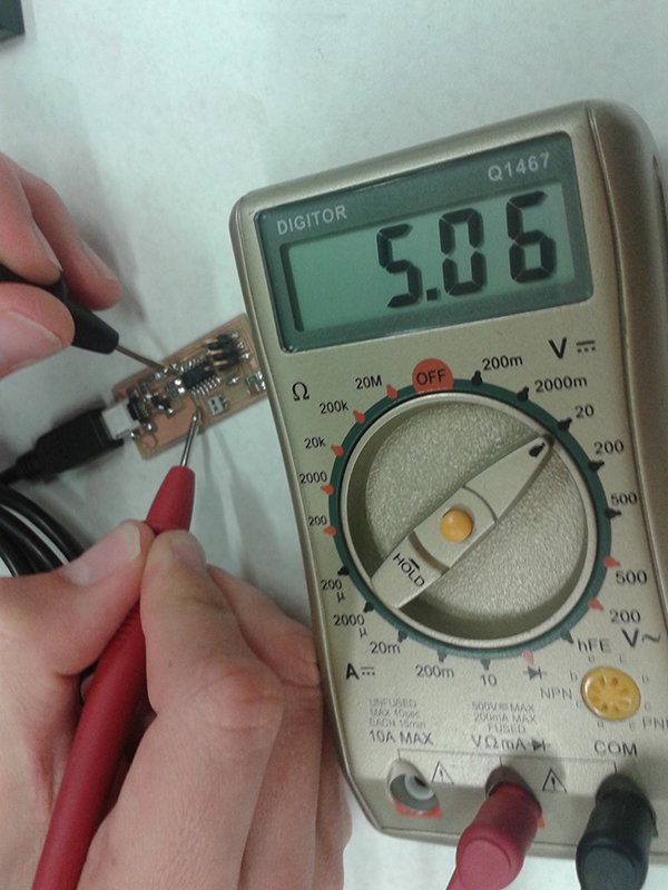
Once the board was complete with everything soldered on and the right way around (which is important) I used a volt meter to test some of my connection with a beep for an indication, instead of just plugging it into the computer. It all seemed to be working great.
I then plugged my board into my computer being careful not to have it on the body on my Mac computer because I had been told it could short circuit my computer boards from Craig. Signs that something was wrong were not happening such as heat and smoke so was really happy about that.
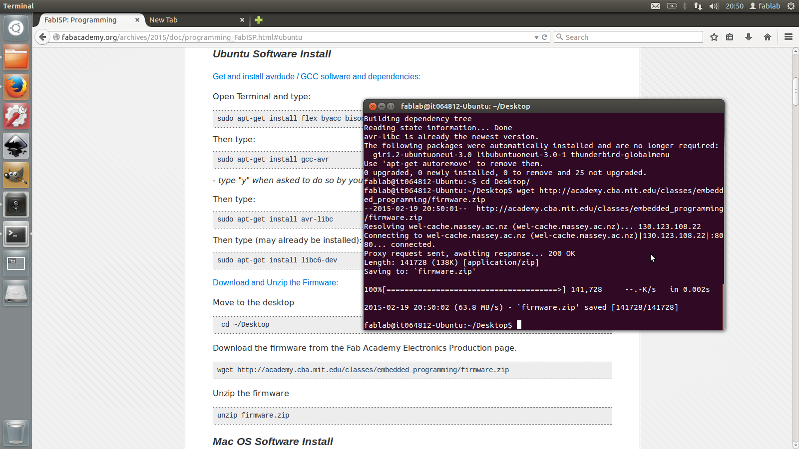
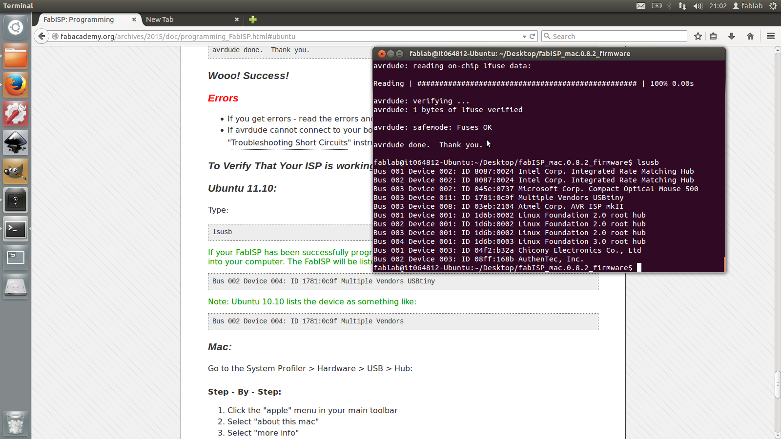
I then followed step by step tutorials that the fab lab had supplied and everything went according to plan, I used CraigŐs board to programme mine which worked well.
Got my control board programmed and checked in my hardware options that my computer was registering it, which it was and then went to remove my jumper components.
Once removed I was done and very happy about what I had achieved with the relatively little knowledge that I had.