Week 18
Project Development
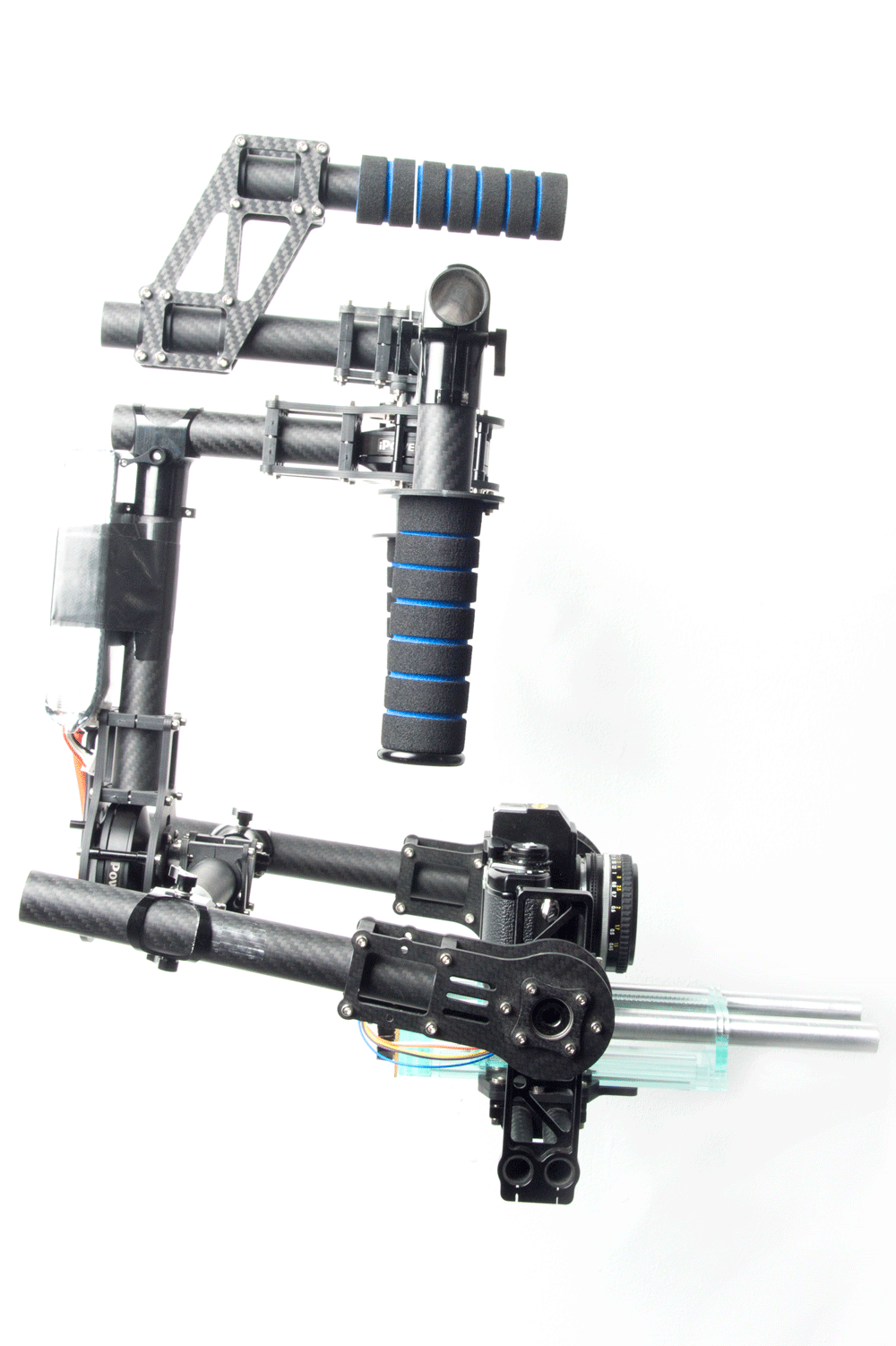
I want to create a self balancing baseplate that sits within a 3 axis camera rig. The baseplate is the object that the camera is fastened to and then slide and screwed into place in the gimbal to balance the 3 axis. I am wanting this baseplate to be universal and be able to fit in pre existing gimbals, most of which have very similar design. I have bought one that I want to use to test the prototypes that I have.
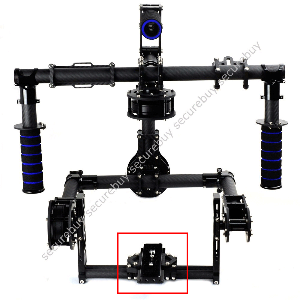
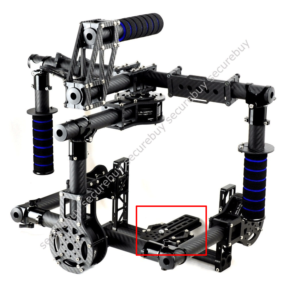
The main purpose of this baseplate will be with the changing of lens where rebalancing is required when the camera is placed in any type of these 3 axis gimbal rigs. The camera needs to be balanced on a roll, pitch and yaw axis which all takes some fine tuning to get the camera to sit right without tipping in different directions. The camera needs to be perfectly balanced so that the motors which control the camera do not need to work against gravity when counter acting movements from the camera user.
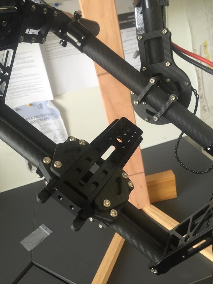
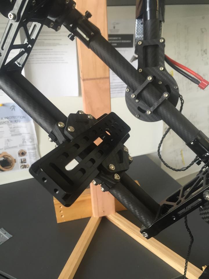
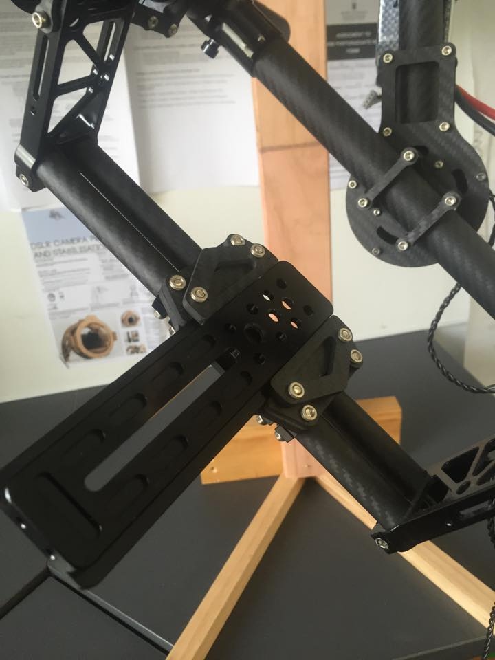
This idea will also help a lot when it comes to changing lens where the camera operator would usually have to pull the camera out of the rig and then change the lens. Then place the camera back onto the baseplate and then rebalance all the axises which can take up to ten minutes. Which is a lot of time when you are on a movie set with lots of people and that are all waiting for you.
I want my camera base plate to move within the gimbal, this would mean when the camera operator can change lens without even taking the camera out of the gimbal and then been able to push a button or something similar where the baseplate would detect the change in balance and push the camera backwards and forwards until an inverted pendulum was recreated. This would dramatically reduce the time it took to change lens.
Some considerations for the design;
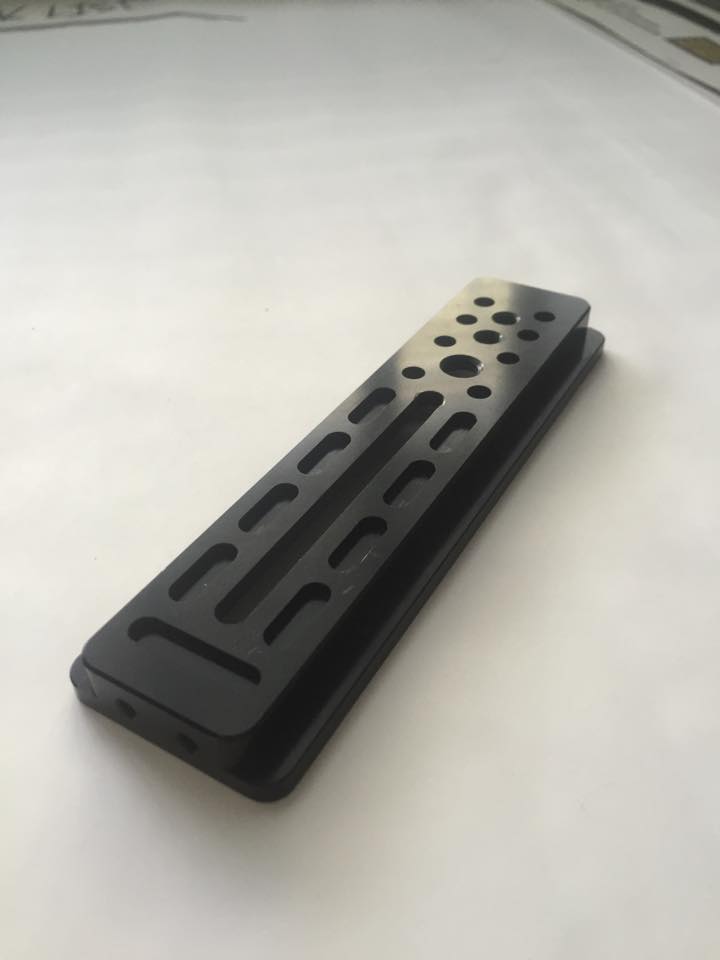
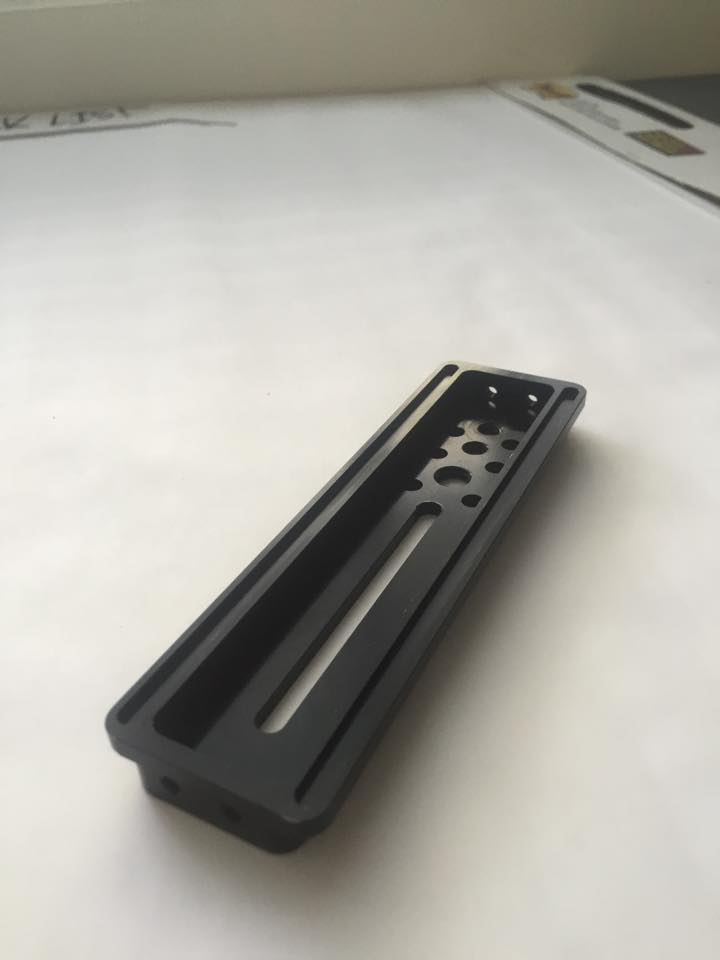
Materials
- I want the materials to be strong enough so that there isn't any vibrations in the joins or material when the gimbal is very shaky areas.
- This will be a very important issue where I am wanting to make it as light weight as possible .
- I was initially thinking that I could laser cut with MDF or something similar to make up some box type structure that are similar to existing baseplate and that I could think of more advanced materials when I had done some more development.
Size
- Where I don't want it to make the camera gimbal any bigger than they are and also want it to fit in the pre existing space for them.
- That I could for prototypes attached the control board on another part of the gimbal so i can keep the baseplate as small as I can
Cost
- I want it to be affordable and this will also be quite dependent on the materials and the type of motor which is used.
Electronics
- Using some type of motor to control the movements. An input for the motors could either be a joystick or and IMU sensor
- Thinking of using a brushless motor because of there size and effectiveness
Concepts
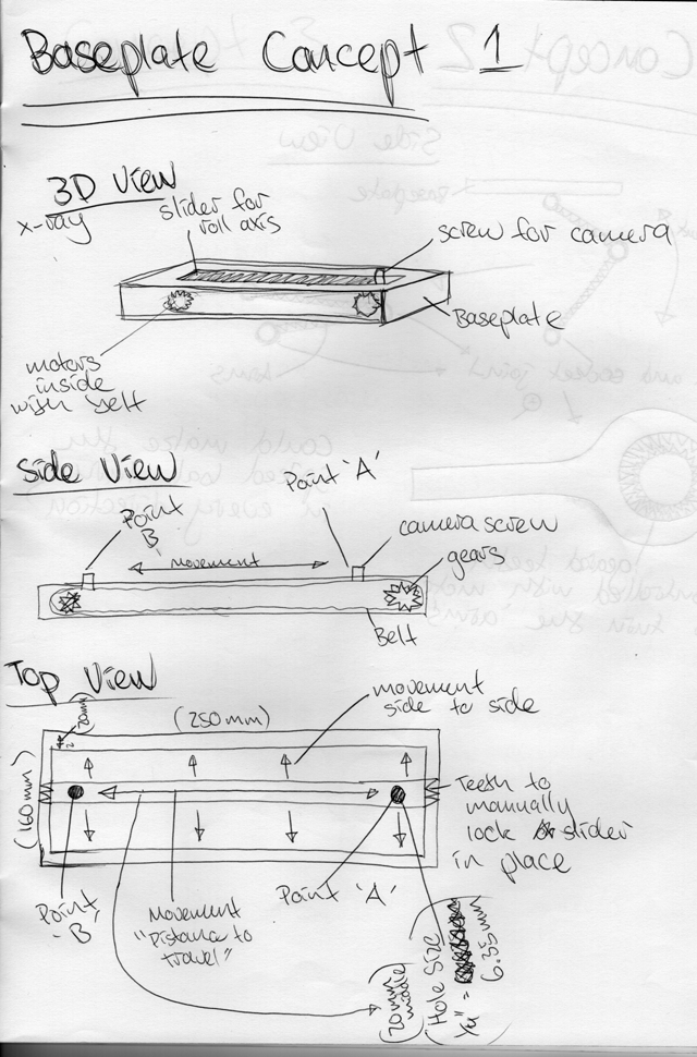
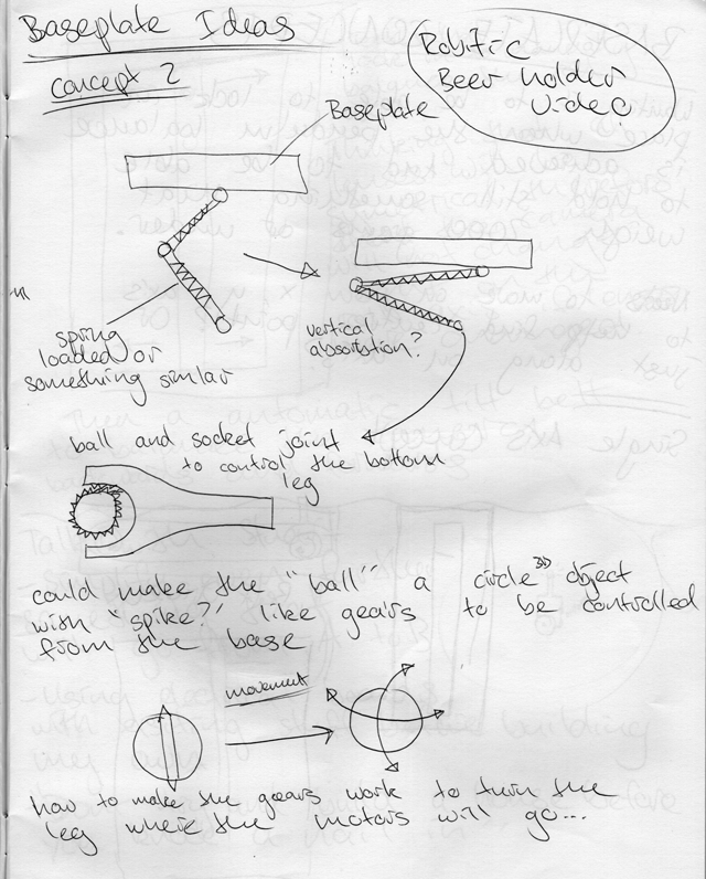
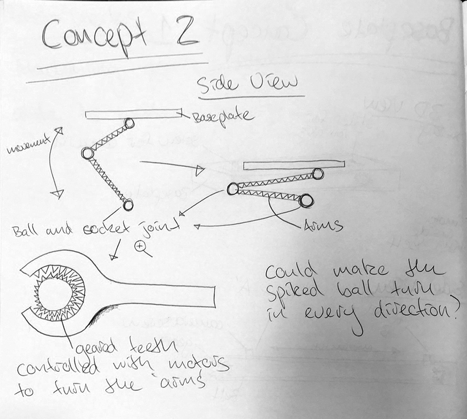
After drawing a few concepts earlier in the diploma I wanted to put this onto a computer so I could start cutting and putting my baseplate together, my chosen workflow was to use illustrator and use the laser cutter to make press fit type models that cold be putting together and also the use of hot glue for some quick prototyping.
I used illustrator through out my design as it was a program that I could use with reasonable great ease and knew how things worked. The image below show the development of my final models. Where I would occasionally print it out and then go and fix all the problems or have a break from my computer and then go and work again and would spot mistakes. This is why I have so many iterations.


These were the final designs where it was very small tweaking to get things right, I had really small tolerances of 0.1 or less because I wanted things to be tight and fit correctly without any play. I tried to utilise the material as much as I could by nesting, I could have gone around some of the shapes and made it so that it was one cut for the outside of the shape rather than cutting of squares and something I will do for future production to save time in the laser cutter.


The first few iterations I was going to use cardboard as my material to get a bit of a feel about the size of the object and what I wanted it to do and how it would fit within my gimbal. Cardboard was also really cheap and awesome for this type of quick prototyping. I did also cut a few things with acrylic.


I few things that I needed to find out about was how the lens support system worked, what the dimensions were of the rods and distance between them. Also the size of the motor that I was going to use and I explain how I chose a motor in my balancer pro page. It was a reasonably small motor and could fit between my rod system which was ideal.
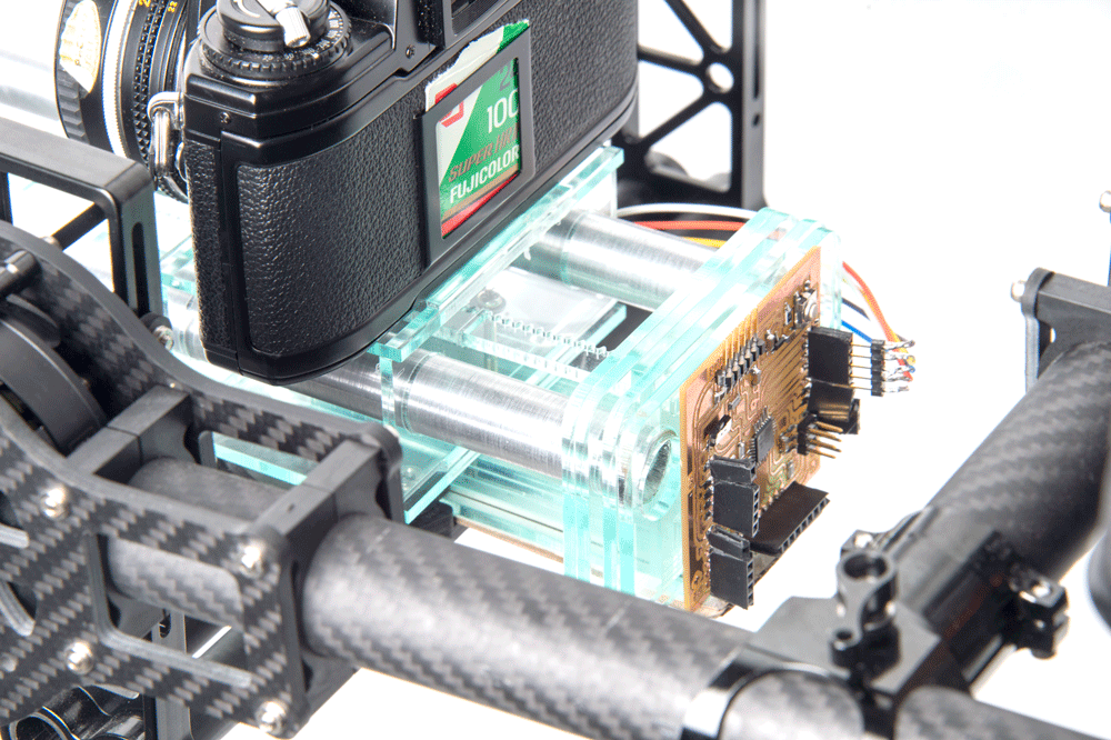
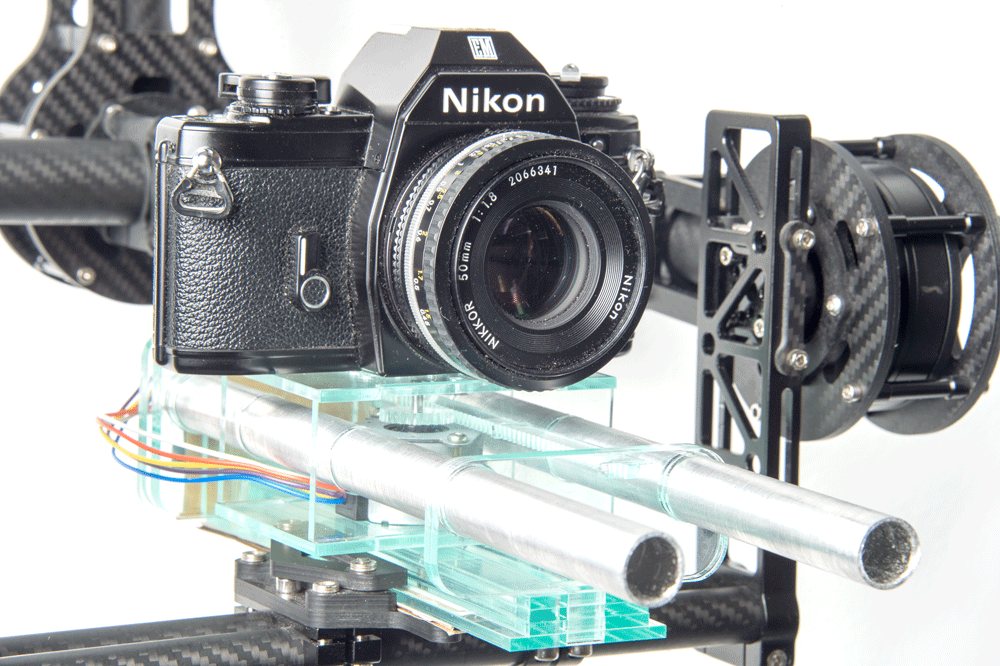
They are 15mm rods with 60mm gaps from centre to centre, I really wanted to try to incorporate this into the design because I thought it would be an awesome added extra feature. This could mean that things like follow focus system could be used and incorporated with the gimbal or baseplate software.


I wanted to print a few designs in acrylic to get a feel for the material and also because I wasn't using grasshopper all my designs were for a specific thickness of acrylic.

This design I went and bought some 16mm wood rod that could be used to replicate the old support system that I wanted to use.

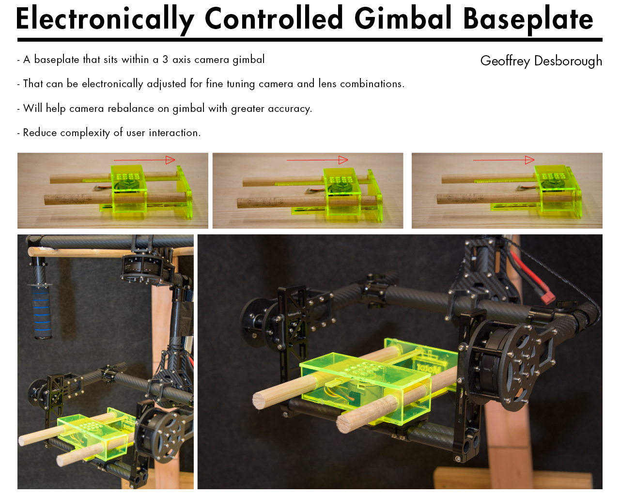
This poster is a draft that I did for our final presentation, I choose to use bright coloured acrylic so that it was visible for what I was creating and what I wanted my baseplate to do. This poster also shows a good comparison is size between how it would fit within the gimbal. The top photo is the poster shows quite clearly how I want the sliding movement to work, the wood had a bit of friction but I was planning to change this.
Final Design
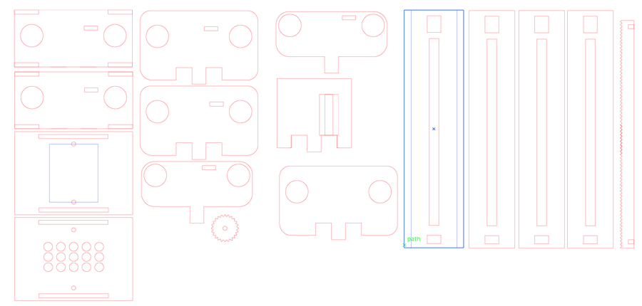
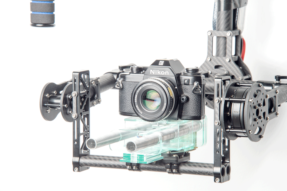
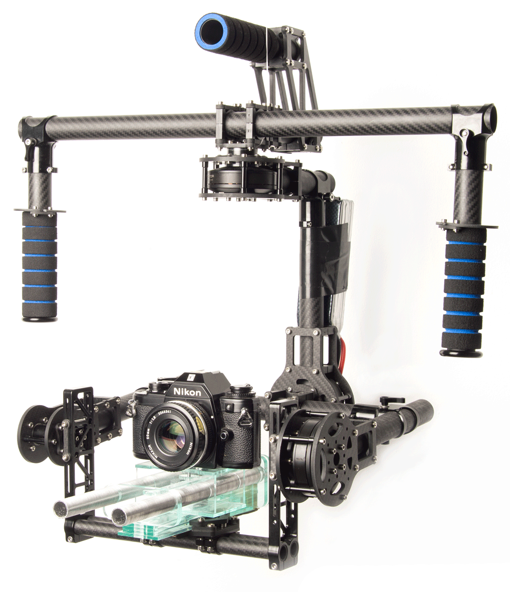
So this design here was the iteration that I got up to before the course finished. It was pretty successful and achieved a lot of my criteria that I write about in my final documentation page. Below are also so images of the final project.
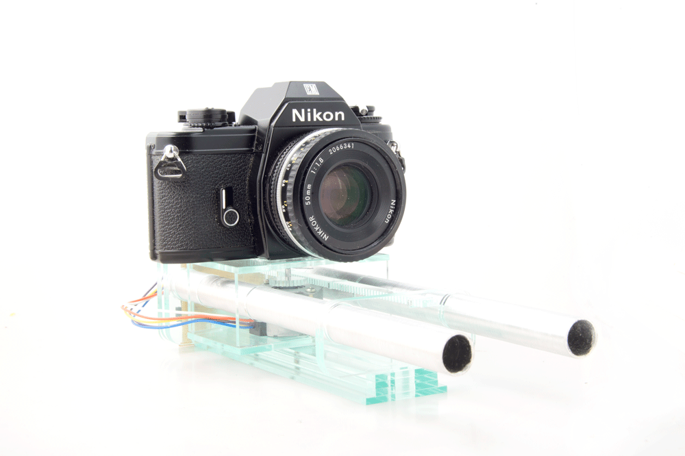
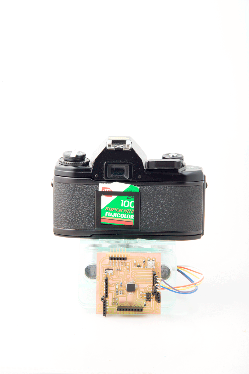
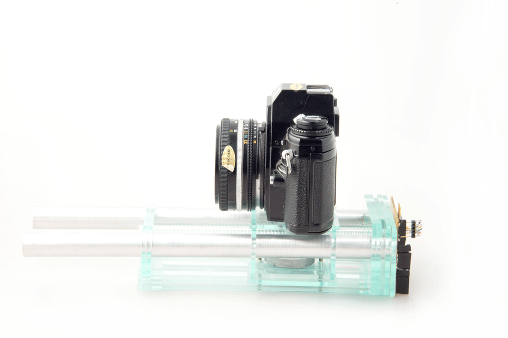
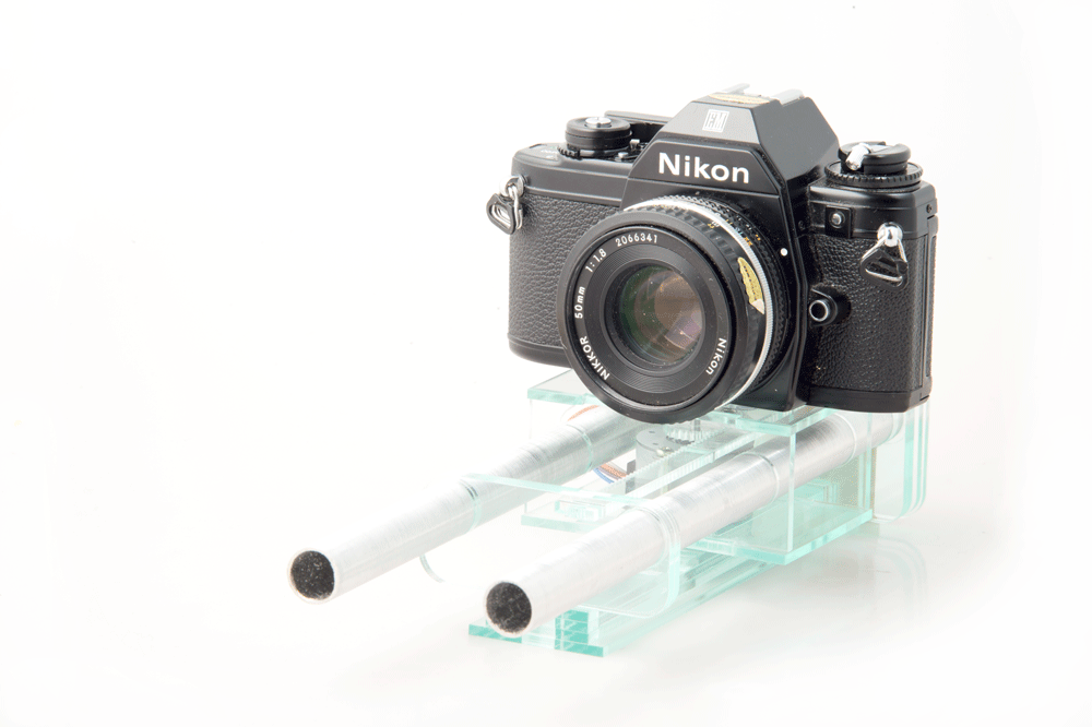
Final Project Background Information
This year I am doing my Masters of Design in Industrial Design at Massey University in Wellington. I have also chosen to complete this Fab Lab Diploma along side it. I wanted to do this diploma to really help with my skills and improve my workflow in this digital fabrication space. I want to make the best use of the Fab Lab to help complete work for my Masters where I want the two final projects to work with each other.
For my Masters I am wanting to create a 3 axis handheld DSLR camera gimbal rig that will provide protection and electronically stabilise for a DSLR camera.
Last year I completed a Bachelor of Design majoring in photography with my area of study been equipment used for image capture for action sports such as BMX, skateboarding and snow sports.
To show the excitement of action sports the photographer or film-maker often needs to shoot from a moving position, for example skiing alongside the subject or using an RPAS (Remote Piloted Aircraft System, also known as a drone). This creates huge technical challenges but technology is advancing rapidly in this area and opening up completely new creative possibilities for photographers and filmmakers.
In particular high definition still and moving image capture is available from dramatically smaller and lighter equipment, and image stabilisation technology allows smooth shots and even automatic tracking of the subject.
However, existing options in the market are relatively expensive due to the sophisticated technology used and hand-made production required. Many of the products on the market also have design weaknesses, especially the ability to protect the equipment when shooting in high risk or moving situations.
I found this to be a massive design opportunity and In 2014 I completed an Industrial Design Paper where we were able to create anything we wanted, this is where I came up with my camera rig idea.
This is a poster we completed for the class showing the type of development I have already done.
