Week 16
Assignment - Propose a final project that integrates the range of units covered:
What will it do?
I want to create a electronically controlled baseplate that sits within a 3 axis gimbal camera rig.
The baseplate is the object that the camera is fastened to which is then slid in and screwed into place in the gimbal. The purpose of the baseplate is to hold the camera in the exact position where its centre of gravity is centred within the gimbal in three dimensions. The camera needs to be perfectly balanced so that the motors which control the camera do not need to work against gravity when counteracting movements from the camera user. This can also cause the motors to over-correct, which can produce vibration and jitter.
The pictures below show the baseplate that is used in the gimbal that I have purchased and I am going to use this as a base for my other designs.
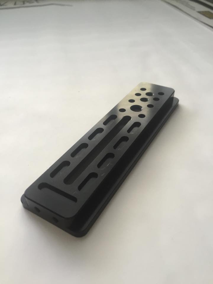
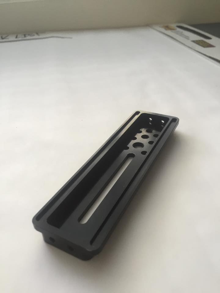
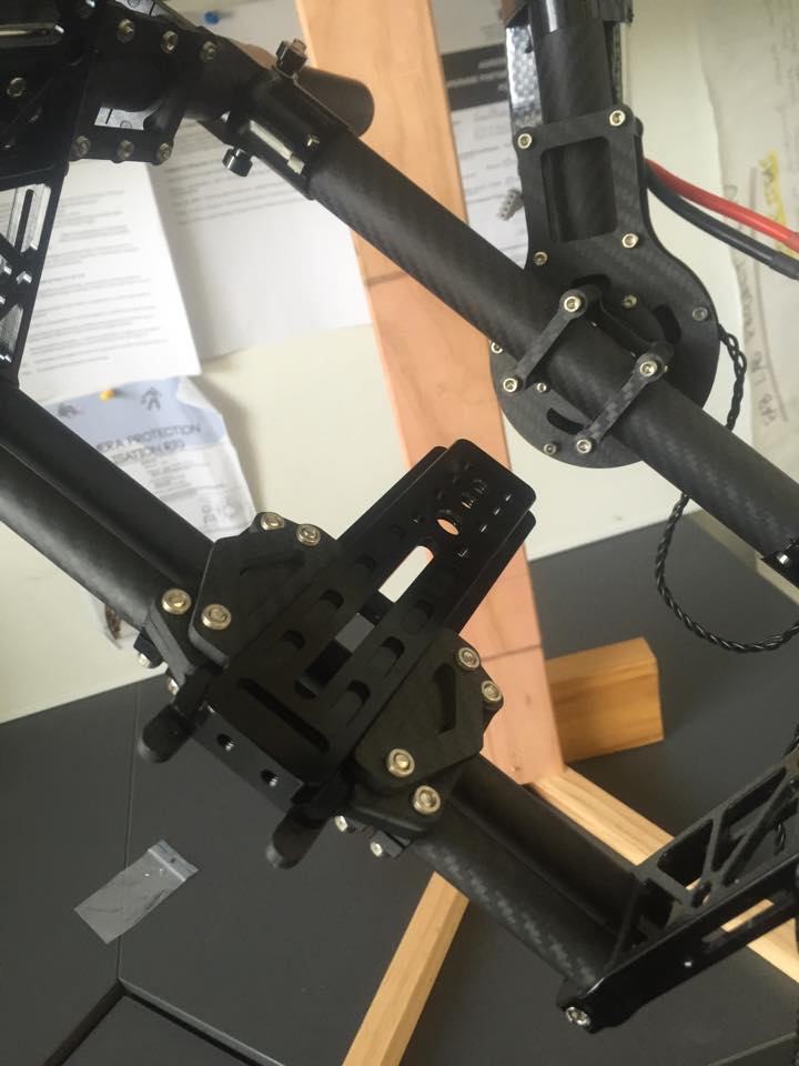
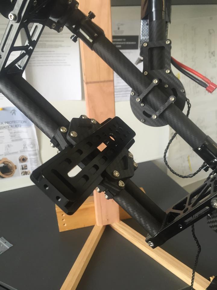
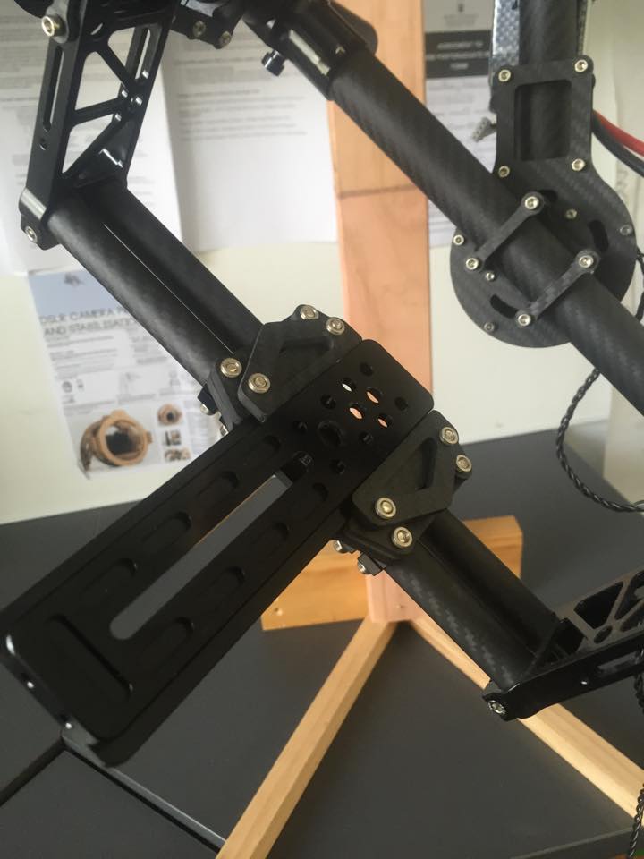
I am wanting this baseplate to be universal and be able to fit in pre-existing gimbals, most of which have very similar design. I have my own gimbal which I will use to test the prototypes I develop.
The primary purpose of this baseplate will be to make changing lenses and the subsequent adjustment much simpler and faster, with greater accuracy of adjustment. This is mainly along with longitudinal axis, i.e. for tilt, because a lens is symmetrical lengthways. This means that once adjusted for tilt, the centre of gravity will be correct for pan:
All of these adjustments are very time-consuming and difficult because they require trial and error, and it can be difficult to know when perfect balance is achieved (for example the tiniest amount of friction on the bearings can affect how the camera moves to a point of balance).
Even with changing lenses the camera operator would usually need to remove the camera from the rig and then change the lens, then attach the camera back to the baseplate, then rebalance which can take up to ten minutes. Which is a lot of time when you are on a shoot with people waiting for you.
I want my camera base plate to move within the gimbal, i.e. electrically driven where the baseplate would detect the change in balance and push the camera backwards and forwards until an inverted pendulum was recreated. This would dramatically reduce the time it took to change lenses.
It could also be developed further to allow for the full range of adjustment required on first set up or when the whole camera is changed, i.e. along the longitudinal, lateral, and vertical axes:
Whos done what beforehand?
This gyroscopic cupholder compensates for the three axes of rotation, and also fore-aft (longitudinal axis) movement: Cupholder
Self leaving beer holder: Self Leaving Beer Holder After this video was realeased it was widely regarded as been a fake computer generator machine, but I really liked the concept.
What materials and components will be required?
- 3D Printed material
- Laser cut ply wood or acrylic
- DC or brushless DC motor. An input for the motors could either be a joystick or and IMU sensor.
- Gyroscopic sensor or input device
- Probably gears or cogs to move the baseplate
- Standard camera mounting screw (1/4-20 UNC or 3/8-16 UNC thread).
I want the materials to be strong enough to resist vibrations in the joins or flex in the material when the gimbal is shaken externally. This will be a very important issue where I am wanting to make it as light weight as possible - essentially in this situation the lighter the better.
I was initially thinking that I could laser cut with MDF or something similar to make up a box type structure that is similar to existing baseplates. Establishing the workability of the concept is probably more important initially, because advanced materials to reduce weight could be introduced later.
For further development, 3-D printing could offer some additional benefits in terms of reducing weight and allowing wider design options.
There is a significant constraint on size and weight. The unit would not be able to exceed the existing envelope of size by very much due to the clearances required in the gimbal system.
Weight is very important for this type of handheld equipment because of the potential for operator fatigue. It is common for gimbals to be made of carbon fibre tubing held together with sleeved jointers, or made from aircraft grade aluminium alloy.
Where will they come from?
- The raw materials should be available from Fab Lab inventory.
- A camera mounting screw would be available from a photographic store.
- General hardware and fixings can be obtained from a hardware store.
- Brushless motors and gyroscopic sensors can be ordered from local electronics stores, or ordered online.
How much will it cost?
- I am planning for all the materials required for development being under NZ$200.
- The target sale price would be under US$100, which would be consistent with this type of accessory.
- The final price would be significantly influenced by whether this had stand-alone controls (more expensive), or was integrated with the camera gimbal or an external smartphone app.
The Babedunio Cost,
- 2 Resistors 49 costing $0.04
- 3 Resistors costing $0.03
- 1 AVR ISP Header costing $1.32
- 1 6-pin Header costing$1.32
- 1 FTDI Header costing $0.06
- 1 Regulator costing $2.04
- 6 Capacitor costing $2.1
- 1 Resonator costing $7.21
- 1 ATMega 328P costing $7.21
- 1 Green LED costing $0.39
- 7 Longpads costing $0.07
Total cost of $6 give or take $1 for using a soldering iron and some solder.
The laser cut cost $120 an hour and the file takes about 10 mins which is $12 machine time
The acrylic which is 600x400 sheet of 3mm clear cost $11.25
The Stepper Motor from Jay car cost $31.90 Stepper Motor
A universal mounting screw will cost $36 Universal Camera Mount
The aluminium pipe that I bought from bunnings cost $4.90 Aluminium Pipe
Total cost to build the Balancer Pro would be = $102.15
This could be decreased quite a bit if there was a 3D printed mounting screw or could find a much cheaper one.
What parts and systems will be made?
- Baseplate housing
- Baseplate slider
- Drive mechanism (cog and cam belt or worm drive)
- Brushless DC motor, gyroscopic sensor, and control board (these may be an integrated unit or the control board could be mounted on another part of the gimbal)
What processes will be used?
- CAD design
- Laser cutting
- CNC routing
- 3-D printing
What tasks need to be completed?
- Finalisation of concept design
- Confirming type of drive mechanisms, and design
- Manufacturing prototype(s)
- Evaluation and refinement
- Final prototype
- Evaluation of manufacturing materials
- Manufacture of finished product
- Evaluation against design objectives
What questions need to be answered?
- Design that minimises flex and movement (by design, and also tolerances)
- How to achieve precise mechanical movement to allow fine adjustment
- Is it possible to fully automate the process, i.e. a sensor that can detect the fine range of movement required, or to have electrically driven adjustment only?
- Can specific adjustment positions be preprogrammed so that they are repeatable, i.e. a setting for a particular lens/camera combination?
- What is the scope to extend the range of adjustment to allow for all three dimensions so that camera and lens could be swapped out for another?
- What materials and manufacturing techniques combinations will produce the best trade-offs between cost and performance, including manufacturing cost?
What is the schedule?
How will it be evaluated?
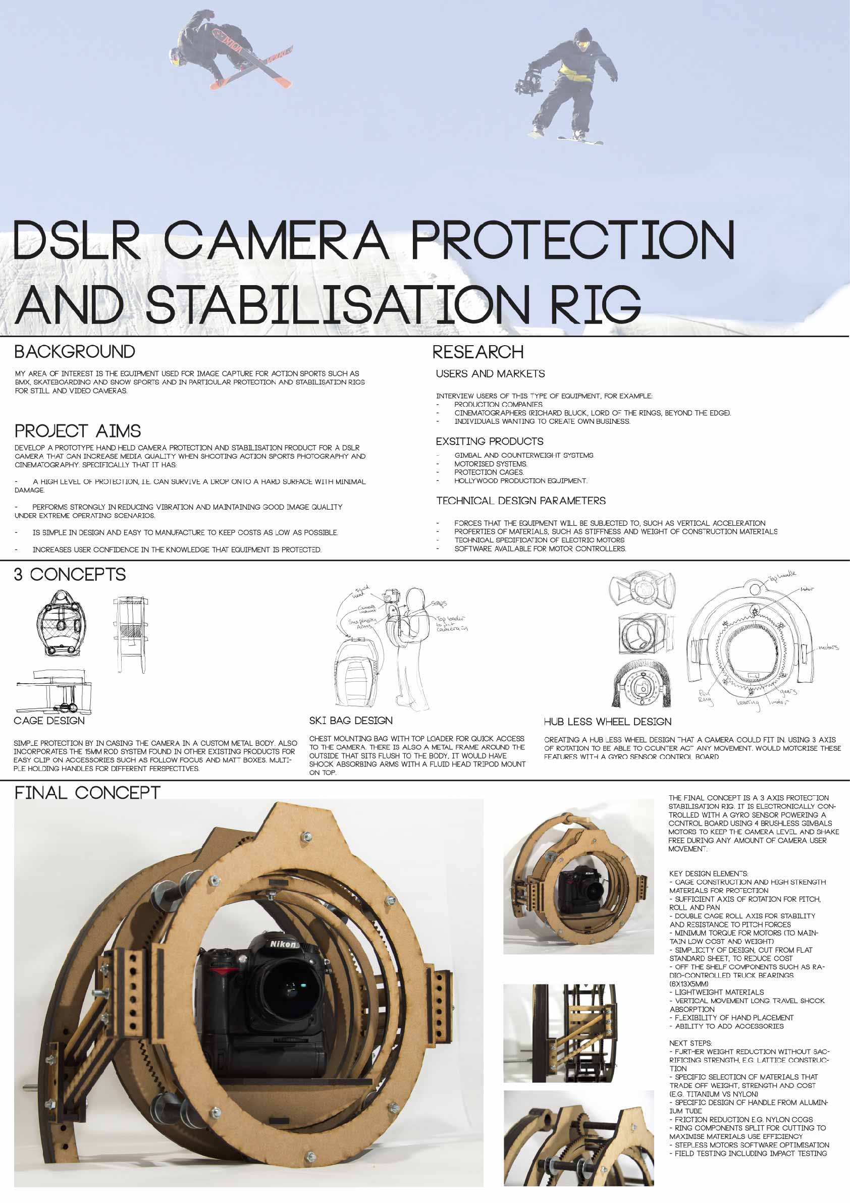
Final Project Background Information
This year I am doing my Masters of Design in Industrial Design at Massey University in Wellington. I have also chosen to complete this Fab Lab Diploma alongside it. I wanted to do this Diploma to really help with my skills and improve my workflow in this digital fabrication space. I want to make the best use of the Fab Lab to help complete work for my Masters where I want the two final projects to work with each other.
For my Masters I am wanting to create a 3 axis handheld DSLR camera gimbal rig that will provide protection and electronically stabilise for a DSLR camera.
Last year I completed a Bachelor of Design majoring in photography with my area of study been equipment used for image capture for action sports such as BMX, skateboarding and snow sports.
To show the excitement of action sports the photographer or film-maker often needs to shoot from a moving position, for example skiing alongside the subject or using an RPAS (Remote Piloted Aircraft System, also known as a drone). This creates huge technical challenges but technology is advancing rapidly in this area and opening up completely new creative possibilities for photographers and filmmakers.
In particular high definition still and moving image capture is available from dramatically smaller and lighter equipment, and image stabilisation technology allows smooth shots and even automatic tracking of the subject.
However, existing options in the market are relatively expensive due to the sophisticated technology used and hand-made production required. Many of the products on the market also have design weaknesses, especially the ability to protect the equipment when shooting in high risk or moving situations.
I found this to be a massive design opportunity and In 2014 I completed an Industrial Design Paper where we were able to create anything we wanted, this is where I came up with my camera rig idea.
This is a poster we completed for the class showing the type of development I have already done. poster