Week 10
Input Devices
Assignment - Measure something: Add a sensor to a microcontroller board that you've designed and read it.
After the lecture I had some ideas on what I wanted to do, I thought initially of doing something involving a joystick which would related to my finally project by been able to control the camera by sliding it backwards and forwards to reach a balancing point (this could very much be a step towards my final project). Also because I thought it would be easier to create the board and do the programming.
The other idea I had was using a gyro sensor and this would ideally be better where I would be able to receive information of positioning where I could counteract this with motors to keep my object (camera) level and reach a balancing point.
After doing some research, what I really want to create in an Inverted pendulum. Inverted Pendulum An inverted pendulum is a pendulum that has its centre of mass above its pivot point.
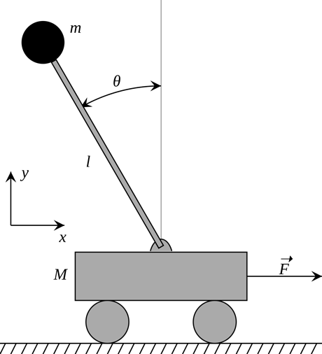
This helps shows that my camera would be the top M and the square down the bottom would act like the motors that I wanting to use to slide the camera backwards and forwards until it reached a balancing point.
Playing around with a gyro sensor would also be very helpful for learning and understanding problems for my Masters project. For my Masters project I am wanting to incorporate 2 or more gyro sensors programmed to a control board.
I went and looked at some of the 2014 students and looked at what they had done, I looked at Chirag Rangholia work where he was wanting his final project to be a Drone. He decided to do something simple for that weeks project by looking at his hello board that he had already made, he wanted to use the button as an import device and read data from when it is pushed. He also states on his page that he was really interested in gyro sensors and would come back to investigate this type of input device later in the course.
I am going to do something similar and make a basic reading from a board that I have already created and then come back to this week when I have more time and am nearing completion of my final project to look at joysticks and gyro sensors.
I am wanting to use Serial Communication and look at how my hello echo and Arduino communicate, especially when the button on my board is pushed.
So my process was very similar to ChiragŐs blog where I needed to debug and remove the RST pin from the FTDI header so that it would stop resetting itself when a message was trying to be sent.
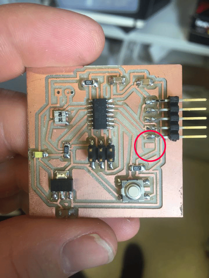
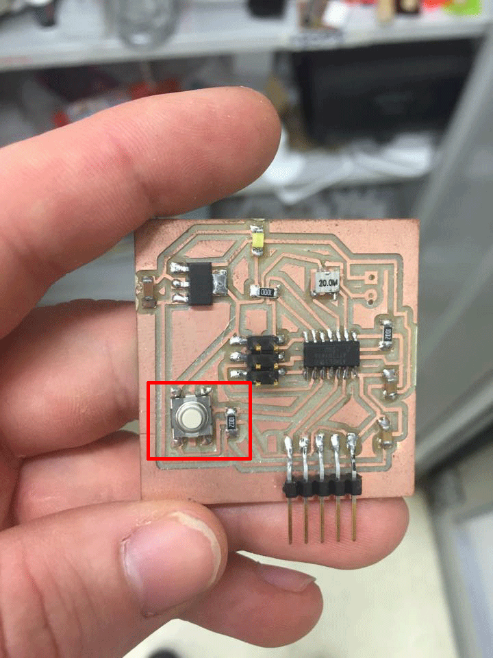
First of all you need to find out that what is the pinout for the button, for that I checked the schematic layout of my Helloecho Board to refer to the pin numbers.
If you have just created this board it would be good to upload a script to make sure the board is working. Use a basic script that I used in week 7 with electronic programming.
In my code I made it so that when the button was pressed it would register that and write Ôbutton pressedŐ in the SoftwareSerial.
Go to Files up the top left - Examples - SoftwareSerial and select SoftwareSerialExample
Change the RX and TX pins to the right number from your schematic number Rx=0 and Tx=1;
Upload your code with the upload button. (top-left corner on the IDE, side of check button)
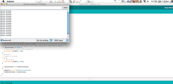
When the button is pressed it registered it had been been pressed and it exampled in my code.