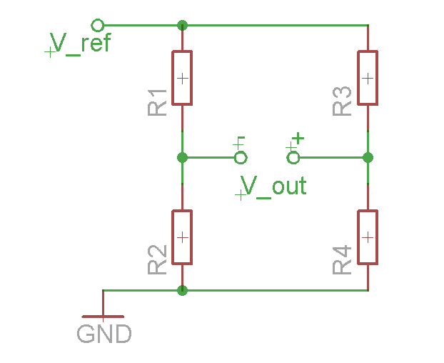
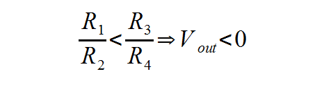
Here's the bridge connection of four resistors (drawn in eagle CAD):
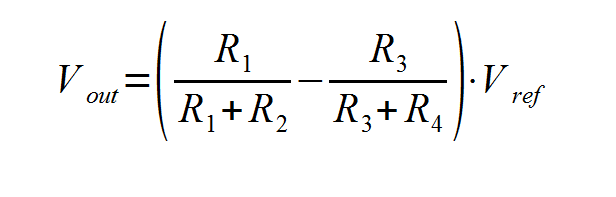
The output voltage can be found using this equation (drawn in LO Math):
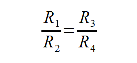
and it will be equal to 0 when
Our assignment for this week was to "measure something: add a sensor to a microcontroller board that you've designed and read it".
To achieve that I decided to to two things:
I decided to fabricate the temperature sensor because I wanted to find out a little more about connecting resistive sensor into the bridge circuit.
Here's the bridge connection of four resistors (drawn in eagle CAD):
|
The output voltage can be found using this equation (drawn in LO Math):
and it will be equal to 0 when |
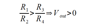
Thus, if those proportions change (If one of those resistances isn't constant i.e. one of resstors is resistive sensor, for example thermoresistor), the voltage measured is changing, and it can be either positive or negative:
|
|
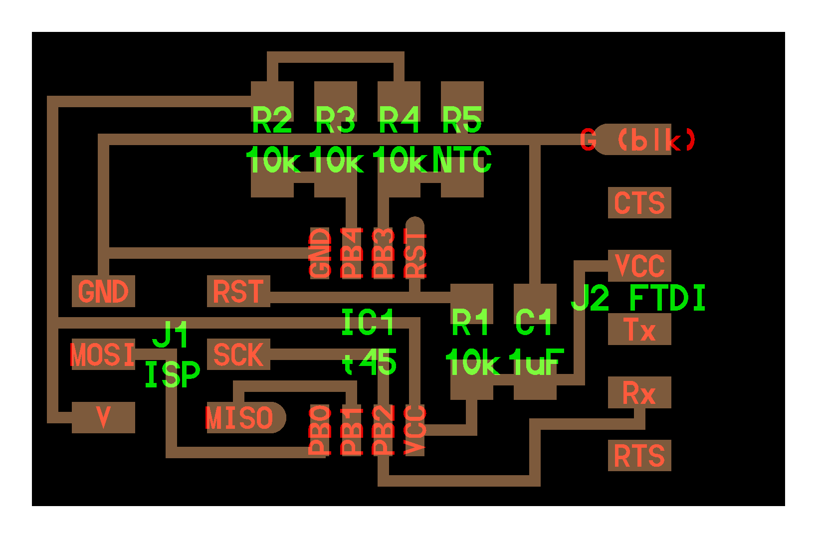
How exactly do we measure this voltage? Do we have a voltmeter inside our microcontroller? Yes, we have ADC. But can it measure the negative values? Not really. That's why we need to use one trick:

That means, that we use two separaate voltmeters (i.e. ADC to measure the voltage on resistors R2 and R1 and then substract one from another to get the signed voltage. This explanation corresponds with pcb tracing shown below.
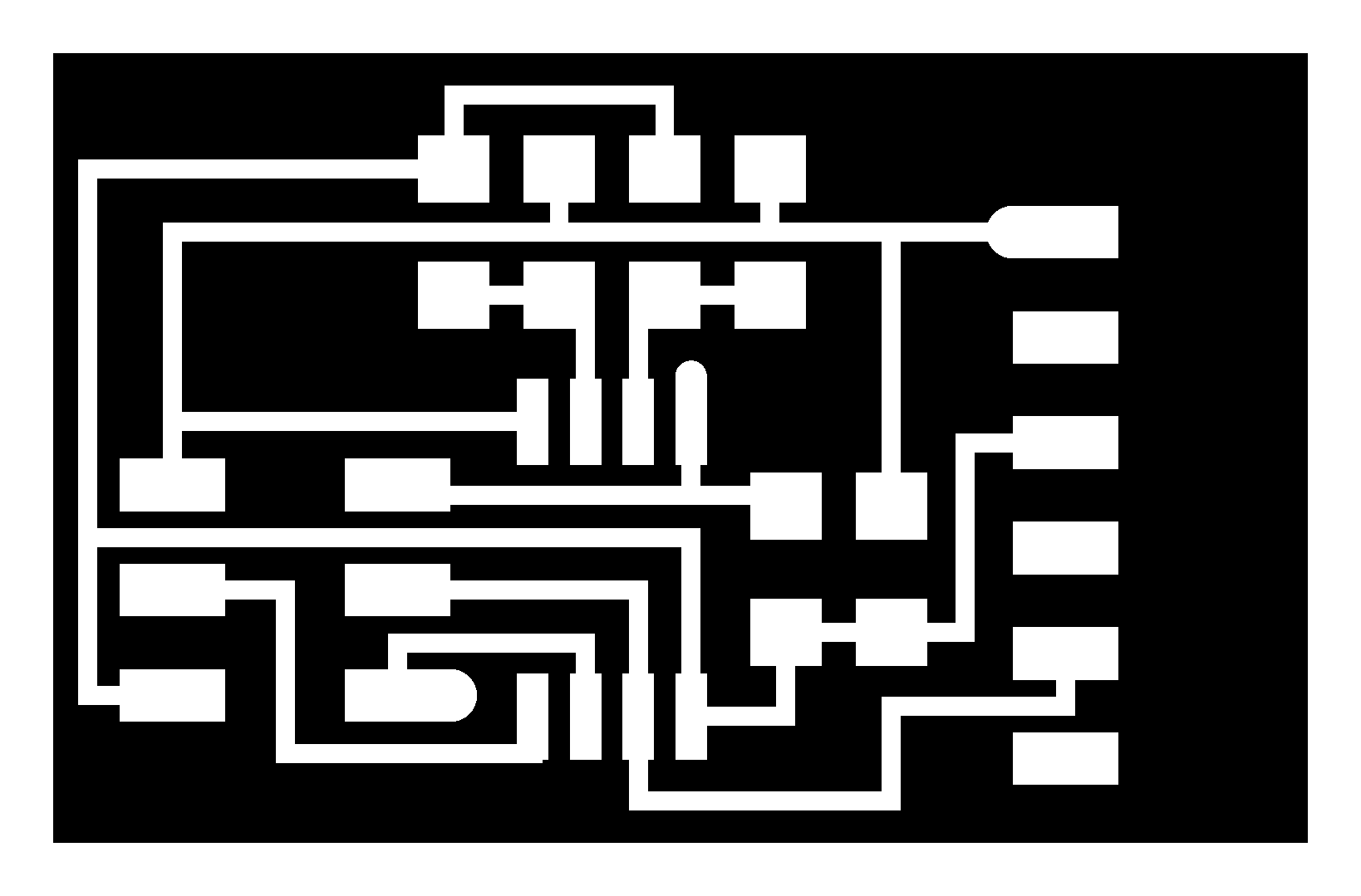
Here are the board, traces and interrior from input devices
|
|

|
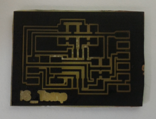
I fabricated this board with my laser-etching technology, which is quite nice and fast. After I cutted the PCB outline in the laser cutter I needed to etch the board till all the outline-copper was removed. And then I needed to remove the paintspray with solvent and had to trim the PCB with file:

While etching... |
...after etching... |
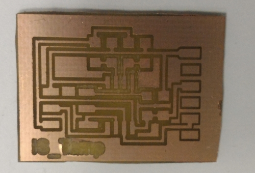
...the paint is removed... |

...finally, it's trimed! |
Then I slodered the PCB:

I took all the files from FabAcademy Input devices page.
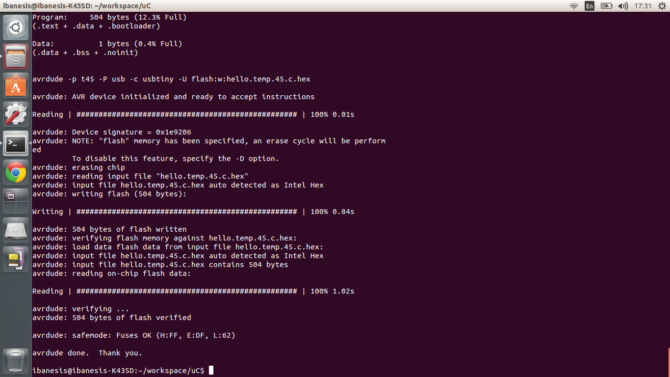
To compile the c-file and then flash with FAb-ISP you need to type (in the folder where you copied the files):
sudo make -f hello.temp.45.make program-usbtiny
Here is what I had as an outpur for this:
To launch the program you need to type (in the folder where you have the python script):
python hello.temp.45.py /dev/tty.usbserial
Where /dev/tty.usbserial is your device name and adress (may vary as far as I know, make sure you're using the right one (type lsusb or try to see the port name in arduino IDE)!
That how it works:
For this week I wanted to make something that I could later use in my final project. And light sensor could be useful!
For this assignment I want to use the very simple sensor: photoresistor. Tough it is for through-hole soldering, it's not a big deal to solder it like an smd-component. This module will not be affected by any machanical tensions, so it is ok not to bother a lot about mechanical durability.
PICTURE OF PCB fabricated is about to appear here
I could use phototransistor too, but it is designed to work well on very specific wavelenght (At least I only had IR), so I was a little worried about how will it work with different types of light-sources. That is the matter of experiment to understand what option is the best. And if so, let's try to make two boards and compare!
For this project I decided to connect the sensor into the voltage-divider scheme, because it is the most simple one. My schematics in eagle looks like this:

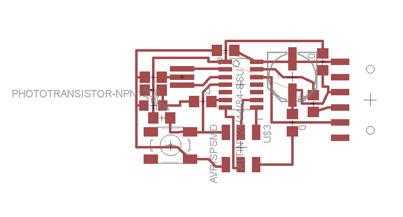
After routing my PCB looks like that:
This time I didn't forget to place an FTDI-connector on the board!
I fabricated it with my good ol'e laser-etching technology.
Pictures here are about to appear
video is about to appear here!
Back to my main page