
Our assignment for this week was to "add an output device to a microcontroller board we've designed and program it to do something". I decided to start from fabricating the hello-stepper board.
I choosed the board for unipolar stepping motor because we use such motors in our machine design project!
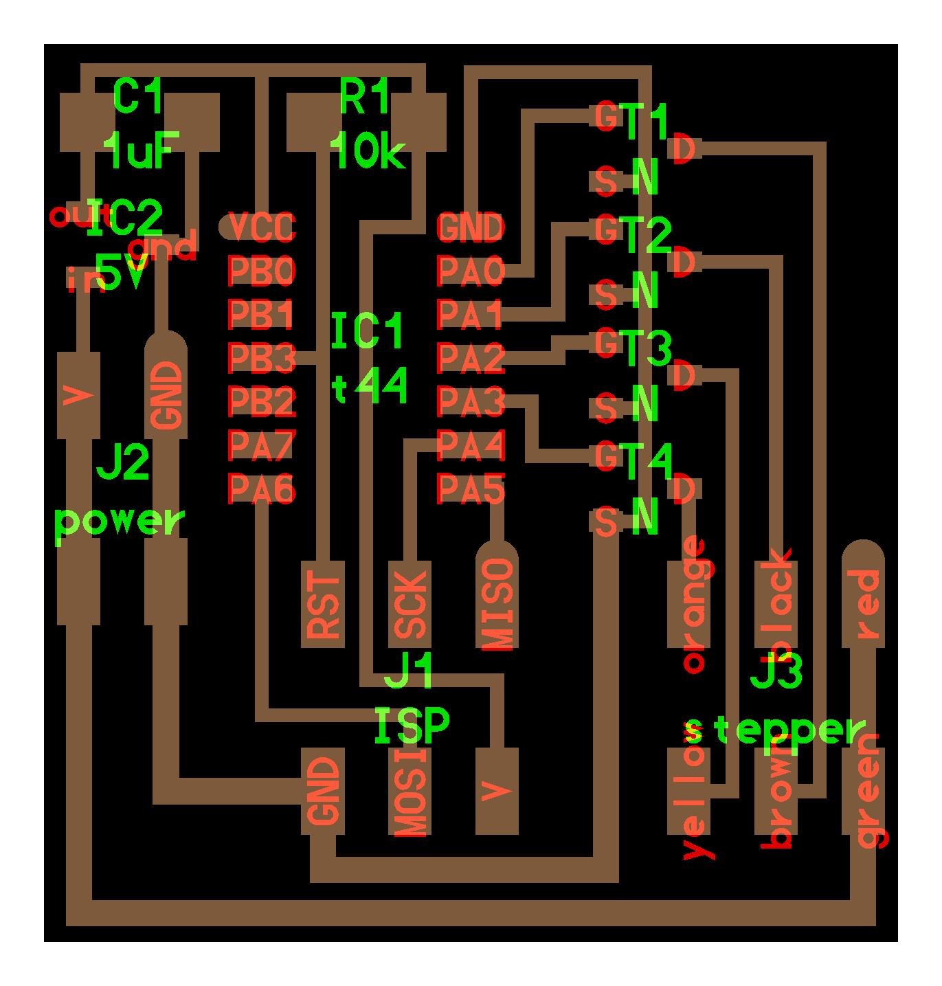
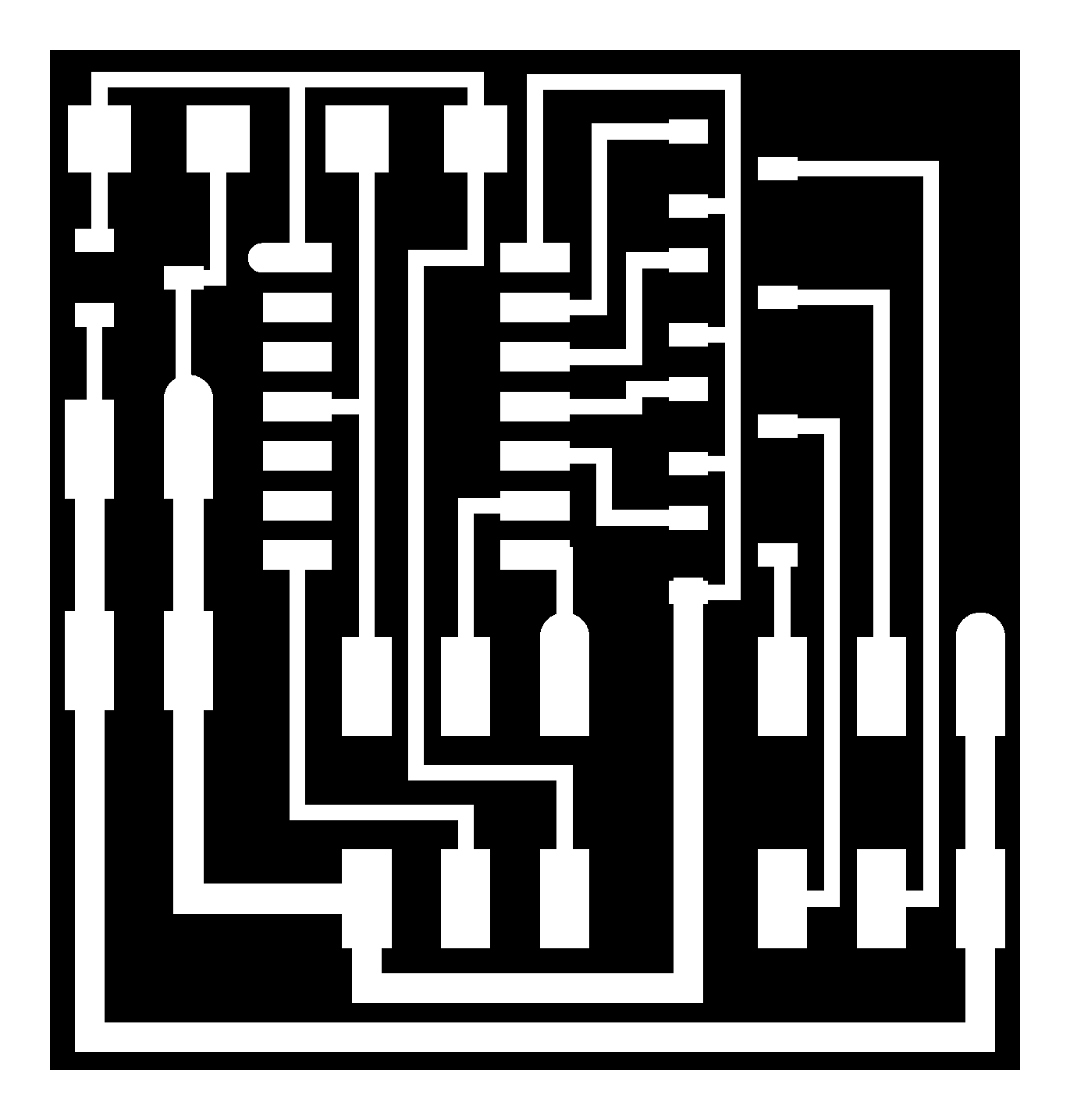
Here are the board, traces and interrior from output devices
|
|
|
|
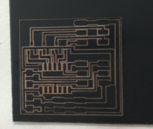
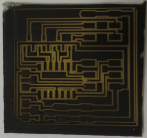
I fabricated this board with my laser-etching technology, which is quite nice and fast. After I cutted the PCB outline in the laser cutter I etched the board till all the outline-copper was removed. And then I need to remove the paintspray with solvent and trim with file:
Traces cut with laser... |

...Cut the edges with dremel (rough)... |
...etched the traces... |
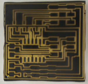
...it's trimed... |
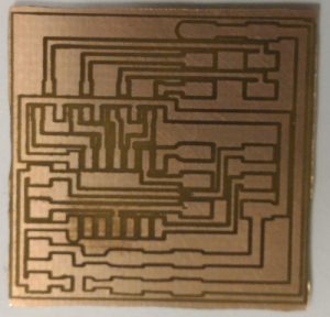
...removed the paintspray with solvent! |
Then I slodered the PCB:

First I tried to use the program examples from FabAcademy output devices page, but it seems that the motor I am using has different pinouts or something, because after flashing it was just trembling.
Then I decided to write the program by myself using arduino IDE:
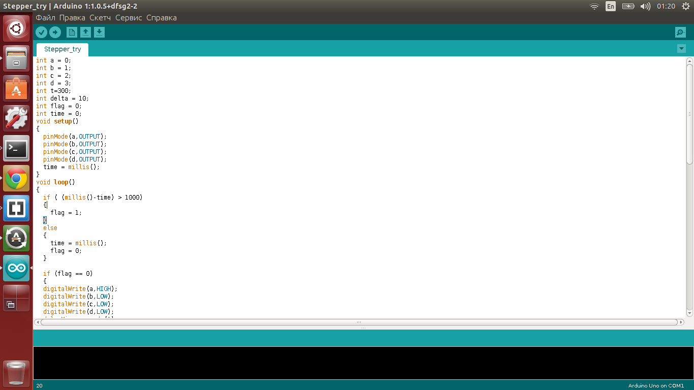
It turns on the mottor coils one by one in the order described in the motor datasheet (see the link above) and the speed is changed by seting the rimeout befor switching to another coil. I also wanted to make a time-set change of direction, but it doesn't seem to work well yet (direction change can be reached by changing the order of coils switching). Here's the source code!
Here is the video of my hello-stepper working:
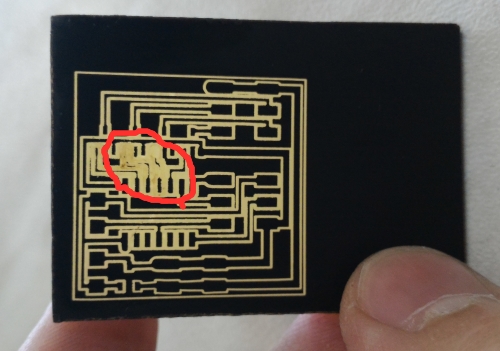
When I was making this PCB for the first time, the traces were too thin and I cutted to much, so after etching the traces were destroyed (Just as they woul be if I milled it with too thick tool we only have now for modella) and I had to make another PCB (the one, that's described above):

|
|