There was a long way from first questioning myself about "what would I like to do for this project?" to this point where I finally decided what do I want. At first I wanted to make some smart-house subsystem. The main point was that the smart-house system was meant to be sparced, spread all over the house and it wasn't easy to decide which part I would like to begin with, and that was the problem.
But then one day my instructor, Ohad, told me to focuse on a single thing that would be much easier to develop, and I decided to make a smart lamp with interesting user interface. I find the theremin interface really interesting and this is a good thing to start my smart-house-developement from studying such a thing!
You may find my early ideas on my previous-idea-page or on my some-more-ideas-page or on my CAD-assignment.
The idea for my final project is to make a lamp (multi-coloured) that is controlled by gestures and provides the end-user with the brand new user experience in customising his surroundings. I call it theremin-lamp after the musical instrument theremin (or thereminvox) and it's inventor, russian engineer and physicist Leo Theremin (because my lamp works on the similar physical principles with this instrument).
I would like to run the spiral developement for this project, so I need to understand what do I want to get in the end and then determine the macro-steps (iterations, spirals):
First I decided to look for any information about making theremin-like things at FabAcademy before.
Search request "theremin" gave me almost no results in capacitive sensors but Casper Koomen page a this year's FabAcademy (quite interesting design!). Not too much.
But searching Capacitive gave me a lot more results (about 50 pages!). I watched first 10 through and find really useful for my project (though many other were really interesting too):
The problem is that most of them are about making touch-sensors and my main point is to make a gesture-sensor, but I hope that everything will be solved simply by incrementing the resistor's values.
It takes laser-cutting, PCB-manufacturig and maybe even CNC-routing to pass through all the basic operations needed to ccreate the lamp. I am thinking about making some interesting covers from composite materials, but that will be later (see the developement process).
Skeleton is made either from cardboard or from thin plywood.
Making electronics needs FR4, microcontrollers and some other details
Cover is made from really thin cardboard now
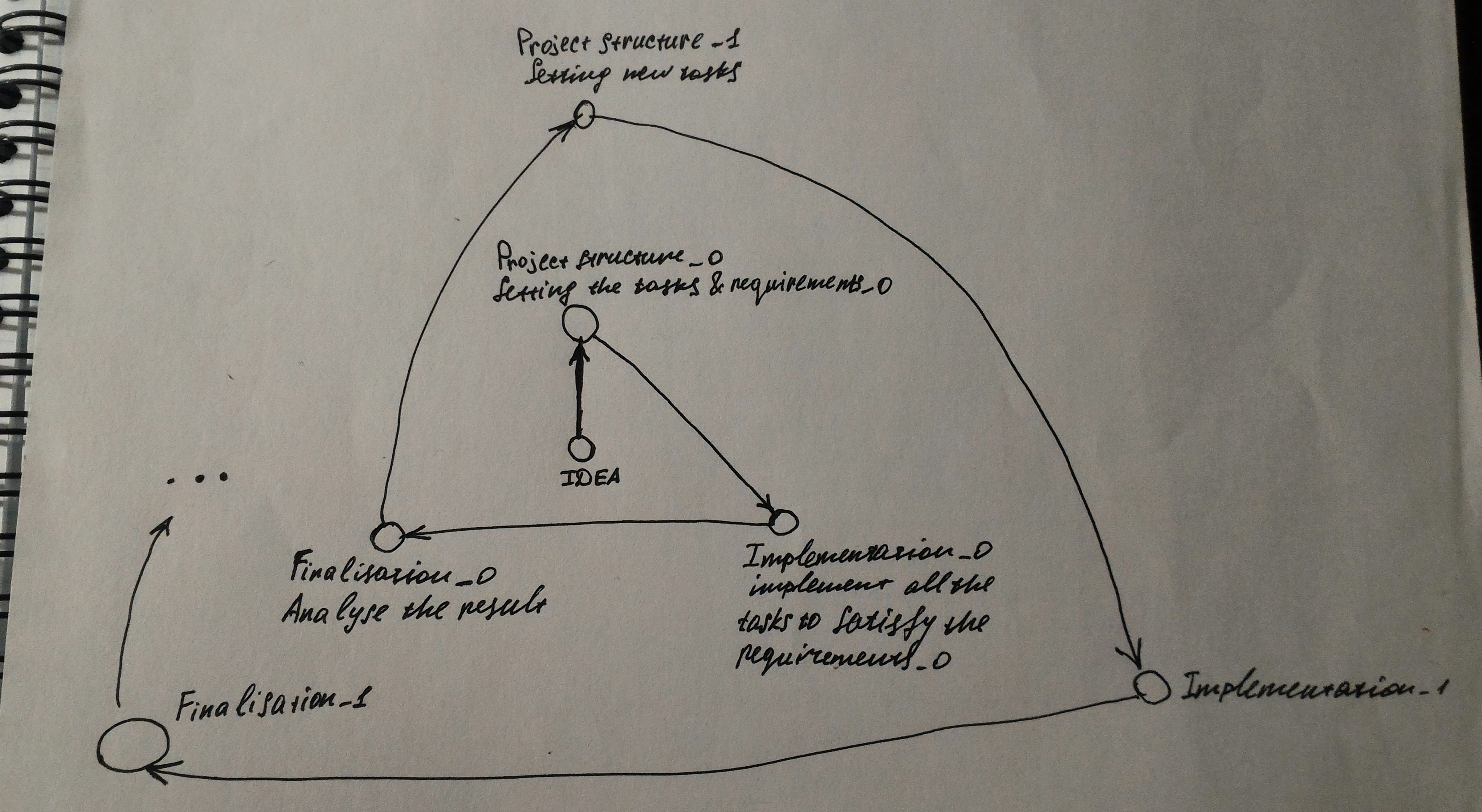
Running the spiral develpement means divide the project into the developement stages. And that is the way I see that:
First step is to determine the desirable result and all the others are attempts to get as close to it as possible concidering that our resources (time first of all) are limited.
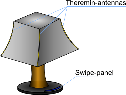
Here is the general (undetailed) description of my project, that is the way I want it to be. I would like to separate it into two concepts: the functional design and styling.
Functionaly my project consist of the following components:
At the same time on the styling side there are some tasks too:
In this iteration_0 the main thing I wanted was to pay as much attention as it's possible to the rapid functional prototyping and the design parts. Thus electronic part is being prototyped in the most fast and simple way - by using breadboards and through-hole circuit boards for prototyping. Thus for this iteration we have one microcontroller that takes information from one input chanel and controls one output chanel.
Here are the tasks (based on the project structure) for iteration_0 functional design:
Here are the tasks (based on the project structure) for iteration_0 styling:
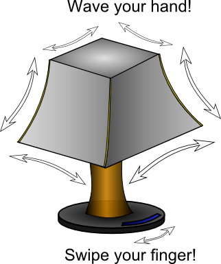
This figures show how does my lamp have to look like and what gestures does it have to understand. Styling depends on both of this criterias and I will be keeping it in mind during all the iterations but on the very beginning (iteration_0) my main priority will be to make a single-input-single-output device to test the sensors and study the related programming.
Attiny44 runs the whole program (gets the data from one capacitive sensor and controls one red LED). I know that it is not really good to use the preadboards (I got away from that in iteration_1) and it is good to make details instead of buying (even if you already have some. Later while replicating it may cause the dependancy on this details and on their reseller) but for now the main priority was to build the working prototype as fast as it's possible, so that's what I've got:
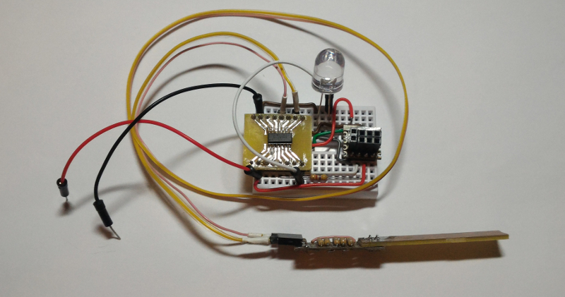
I have all the connections needed to make the controller work (reser is pulled up) and be flashed (you may see specially soldered for such occasions connector) with FAB_ISP. At this point everything is powered from Arduino Uno (I connect black and red wire to 5V and GND). That is the most simple way to prototype (yet not always the most stable!).
That's how does it work (so far):
It runs the very simple program: when any conductor (my hand for example) is getting closer to the sensor, the LED starts to shine brighter and when you get the conductor away, it fades.
I made a program in the arduino IDE (here is the source sketch if you want to try it), it contains the basic arduino capacitive sensor library (desctiption and how-to-use are here). You may find the instructions about how to use attiny44 with arduino IDE here.
And yes, the LED is HUGE!
As I wrote above, there are some requirements on styling. To reach this goals I decided to make a press-fit kit from cardboard at first:
At this point I am not making the central column and the lamp base. It is up to further iterations.
That's how does it look after laser-cutting (with epilog helix laser, speed = 30,power = 40, frequency = 500) and assembling:
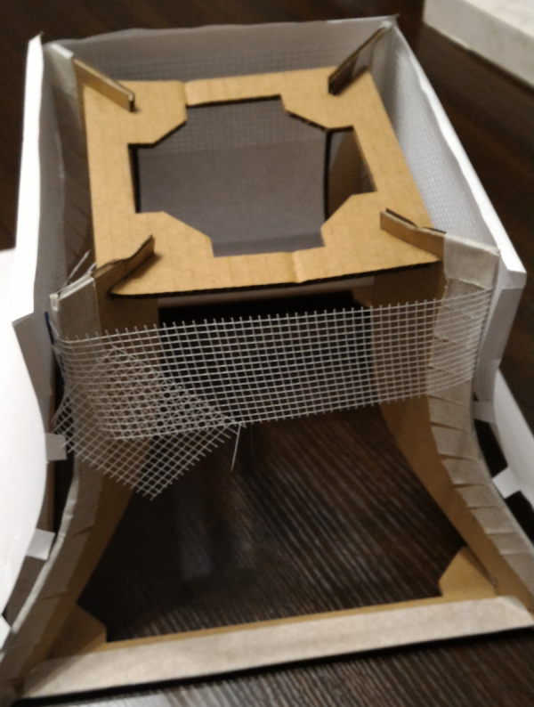
As you see, the lamp looks nice. In fact there was a little problem with assembling it, maybe I little messed up with sizes, but I will make 3D-model to check out for sure during the next iteration.
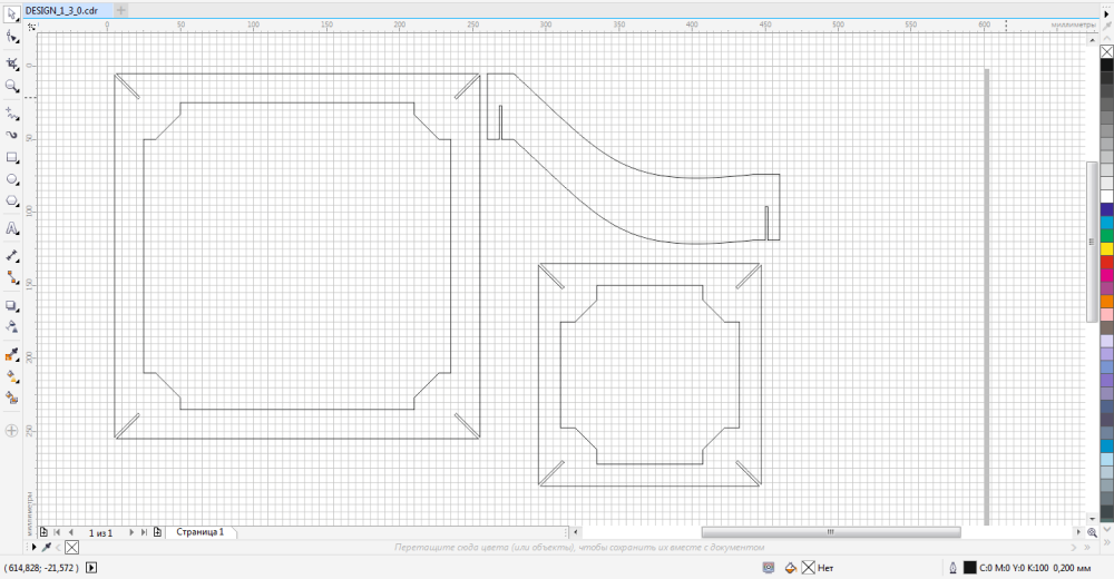
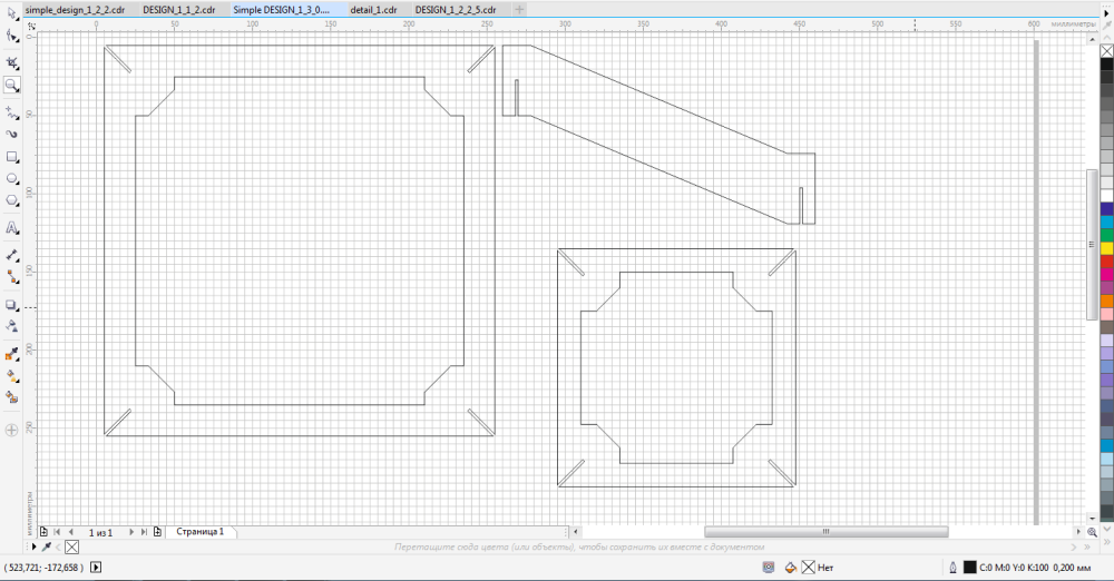
The next step is to make the musical-stylized cover. To reach this goal I decided to put different musical patterns on the cover and laser-cut them. Sounds easy, doesn't it? Still, there is a little problem: the shape of side surface is a little complicated and it is not easy to make it's planar scan (not only planar projections) and I had to measue this shape from the assembled lamp by attaching the paper to it and tracing the touch outline. After that I tried to digitise it in CorelDraw and that's what I've got:

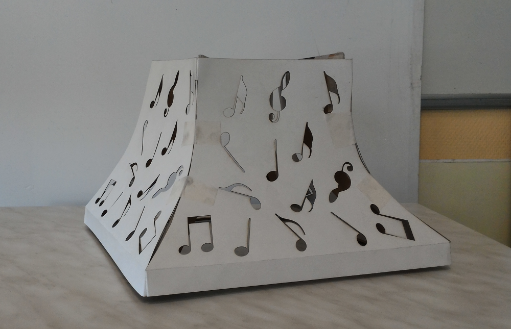
And that's what do we have when everything is cut:
There are some things that didn't work really good:
What I have for now is:
|
Assembled lamp:
|
Working single-input/single-output prototype:
|
After I made a single-input/single-output device in the iteration_0 it's time to play with more complicated things!
Now I want my lamp (based on the fabkit from now on) to work with multiple inputs and outputs. All those sensors and actuators have to be fabricated PCB-s I could use with FabKit.
I also want to make sure everything is ok with my 2d-design (by making 3d-design for my lamp). In fact I want it to be more simple to avoid the problem with side surface (It makes the lamp a little less stylish IMHO but at the same time it ease makint the cover a lot, because in the next iterations the shape of the lamp will be pyramidal!
Here are the tasks (based on project structure) for iteration_1 functional design:
Here are the tasks (based on the project structure) for iteration_1 styling:
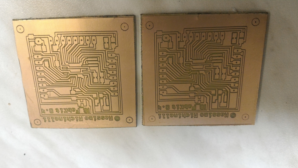
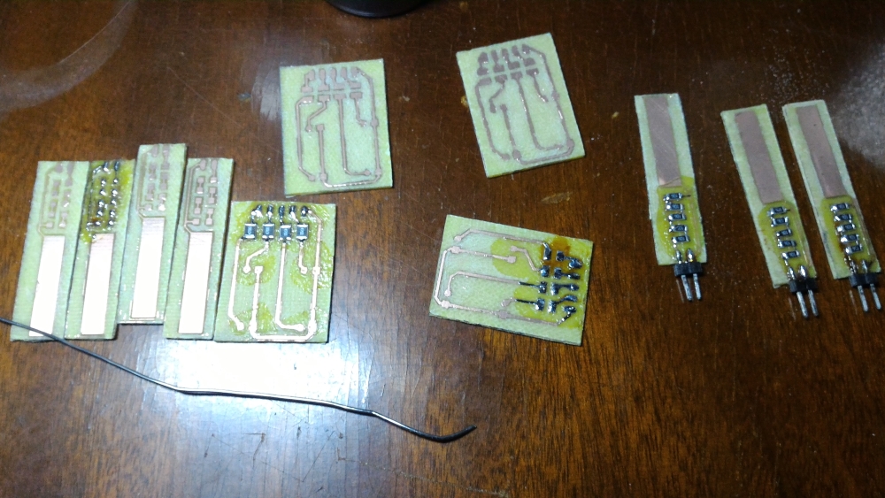
That's what I've succeeded to fabricate:
Etched the PCB's
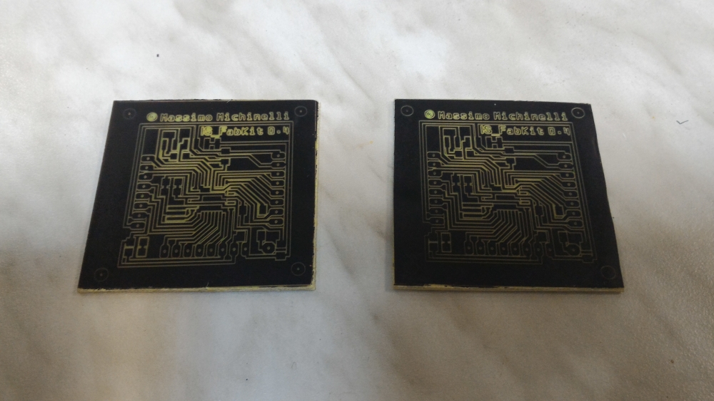
Rinsed them to clean the paintspray
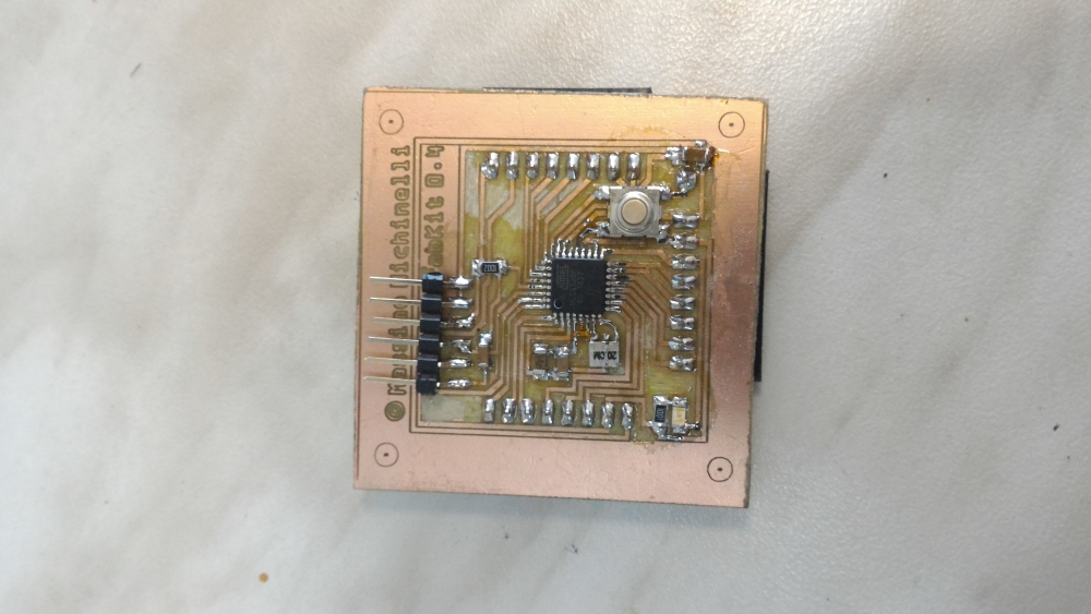
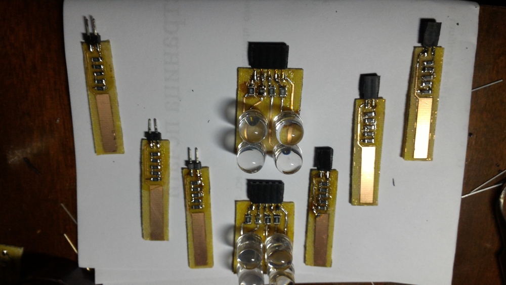
Soldered the FabKit:
That's what I've succeeded to fabricate:
Lasercutted the paintspray
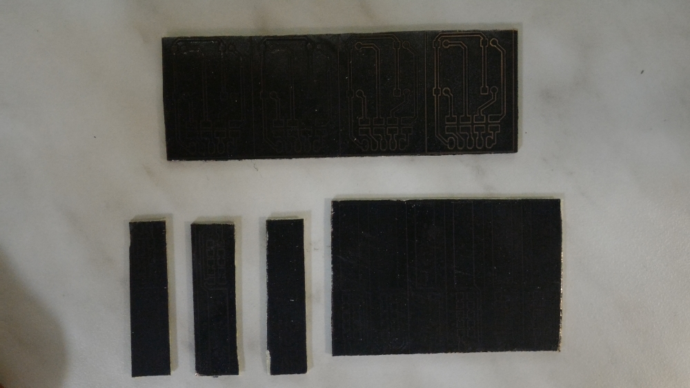
Etched the PCB's
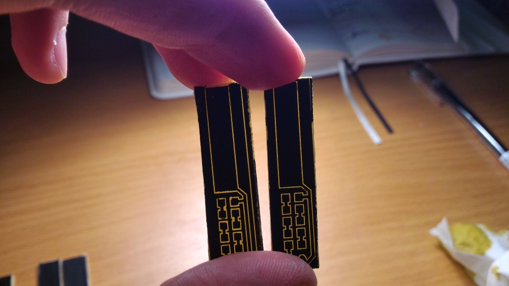
And soldered them:
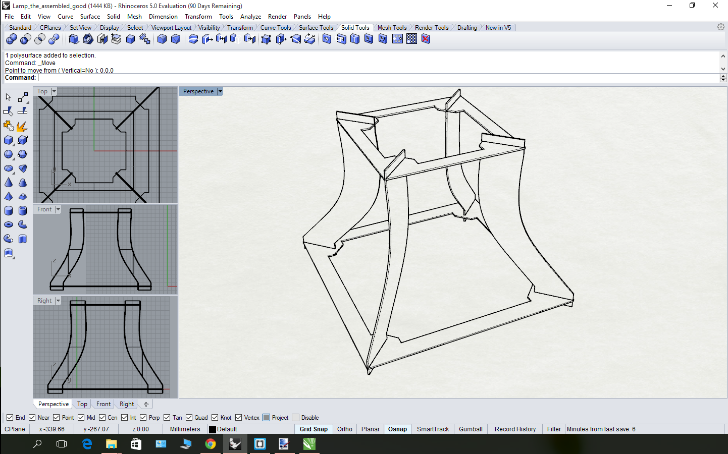
To reach this goal I made exported my 2d-design from coreldraw (cdr -> dxf) and then imported it in rhino. I wanted to use 123D-design at first, but there were some problems with scaling while importing svg-files I've got after exporting details from coreldraw (cdr->svg). So I decided to try anything else and I choose rhino after my instructor's recommendations.
That was really wise choise because rhino turned out to be really easy-to-start thing for me. You may find some more details at my CAD-seek page, but to be short - that's what I had as the firt result:
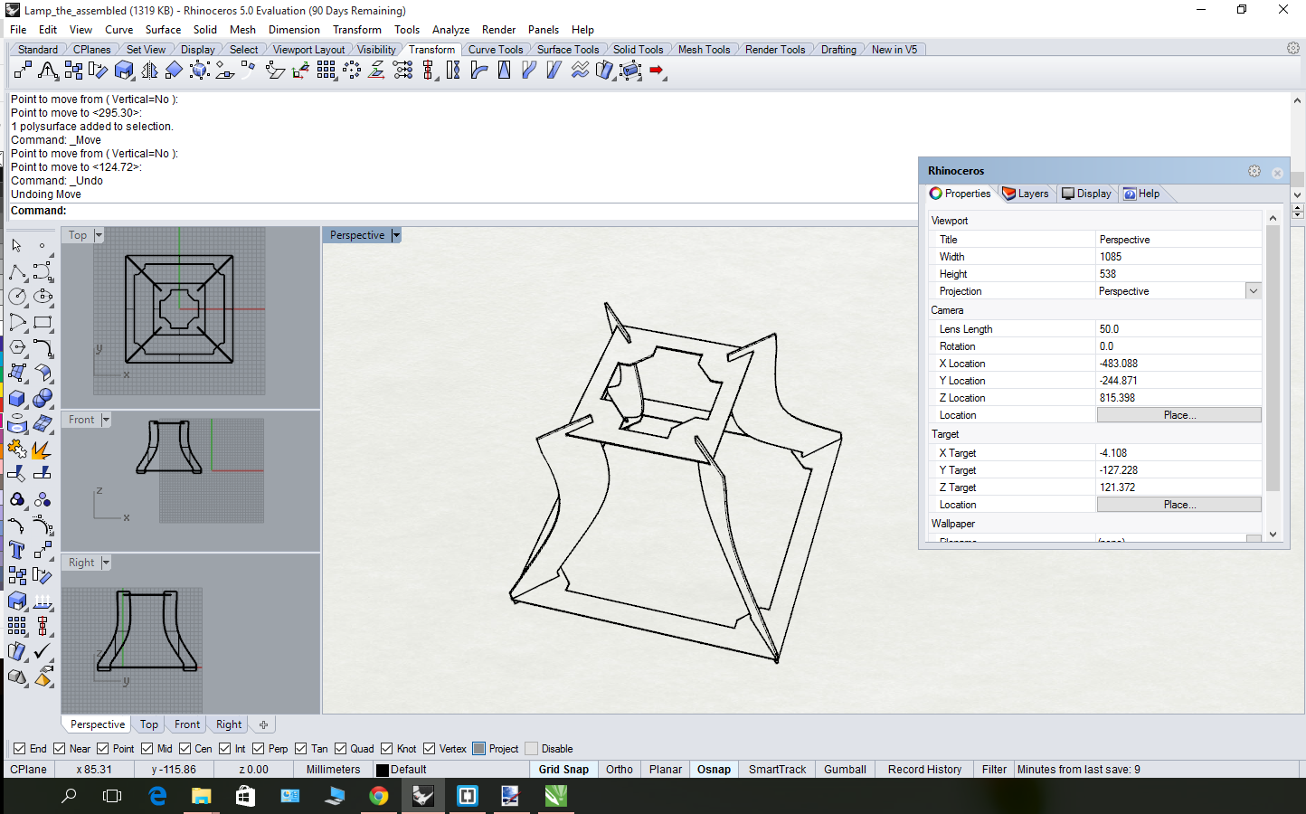
As you see, I really messed up with sizes and the next thing to do was to fix it.
After 3D-modelling my lamp I understood that I have either to change the side ribs, or change the upper part. I choose the second option, because it was way more simple (and it increases the "window" at the top of the lamp, where I can put another LED-panel.
That is how it all looked like before and how does it looks like now:
Before fixing:
After fixing:
I also fixed the 3D-design and now it really can be assembled:
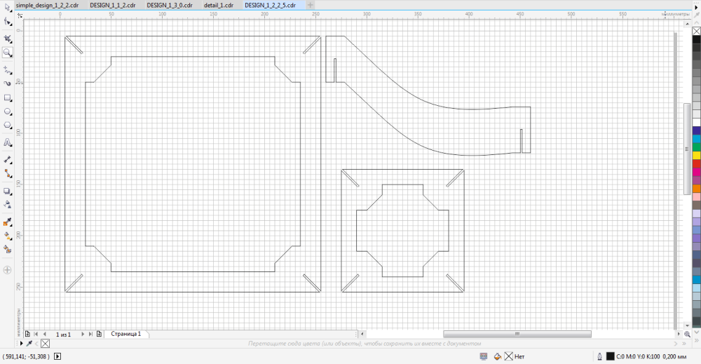
The other thing to do with 2d-design was to make the ribs shapes be more simple (that's because I want to experiment with minimalistic design and also it is really difficult to make side surface blueprints with patterns. That is the result:
The main thing about this iteration was to make a progress from the previous state, and it seems to me that this goal I've reached. Rhino experience was really interesting and making new PCB's was really cool!
The only thing that's left to do here is to program my ThereminLamp!