 Fletch's Fab Academy 2014 Blog
16. Final Project - A Digital, Modular Synthesizer
16.01 Concept.
I originally planned a different final project, but I've changed my
mind about it so many times during the semester whilst searching for
something that I feel has merit that changing once more won't
hurt. Neils comment about the Moog synth last week caught my
imagination and so my final project concept is now as follows:
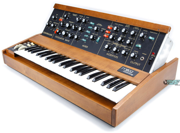
Re-create a modular Moog synth loosely based on the capabilities of
the Minimoog where all signals are processed digitally and each
module contains a single ATTiny to perform the digital signal
processing.
I'm not musical, don't play any instrument and before this project
have never investigated how a Moog synth works in anything more than
a cursory way, so this should be 'interesting'!
For old project concepts see here and here.
16.02 Design Brief.
Create a series of separate 'modules' which can be connected
together in different orders to configure the signal path of the
synth. There should be an input device so that the synth can
be 'played'. There should be an output device that can be
connected to standard audio equipment so that the user can here the
sounds produced. There should be no need to compromise on
audio quality. The device should be fun and easy to connect up
in different sequences, allowing the user to take pleasure in
exploring the sounds produced. The device should be visually
appealing, maybe even beautiful!
All signals between modules should be digital, including any control
and gate voltages. The final project is only required to be
mono as opposed to stereo and isn't required to be polyphonic.
16.03 Final Evaluation.
Once complete I'll ask Hayden the Manchester Fab Lab Manager to
'test' my synth. Hayden plays keyboards professionally, if he
can make my project sound even vaguely musical then I've succeeded!
16.04 Other Work in the Same Field.
I've not done an exhaustive search. Obviously there are the
commercial digital synthesizers from companies like Roland and Korg,
but most of the open source synths I could find are all analog based
or where they're digital they're monolithic designs not
modular. Some interesting links:
Shawn Wallace Fluxamasynth - http://www.fluxly.com/blog/2010/11/fluxamasynth.html
Cool hexagon touch pad chord generator input device - http://cucfablab.org/image/hyveworkshopflyer10png
Bhoreal, Midi input device - http://www.fablabbcn.org/2013/04/fab-lab-bcn-recommends-bhoreal-midi-controller-in-goteo/
Little Bits synth kit, it's analog but similar to my modular concept
- http://littlebits.cc/kits/synth-kit
Fabbermuino, digital but based on a single arduino - http://jackletjacklet.blogspot.co.uk/2011/08/fabbermuino.html
Bob Moog talks
about analog vs. digital sound synthesis - http://www.moogmusic.com/legacy/conversation-bob-moog-analog-vs-digital-sound-generation
16.05 Design.
As a starting point for the functionality and signal path of this
design I've referred a lot to the original Minimoog documentation
from www.fantasyjackpalance.com.
However visually I intend to make it completely different.
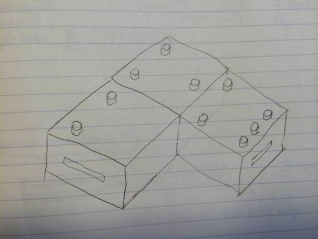
16.05.1 The Modules Concept.
Rather than patch leads I'd like physical modules that you connect
to make the signal path by either stacking or connecting at the
edges. The intention is that almost all of the modules will
actually be the same design, they will have different software
loaded onto them and may have different components (such as control
knobs or connectors) actually populated on the PCB.
Looking at the signal paths in more detail (see below) 5 control
pots should be the max required by any module, these would be used
to generate analog control or to select between module
functions. Switches would be replaced by the concept of adding
/ removing modules from the signal path.
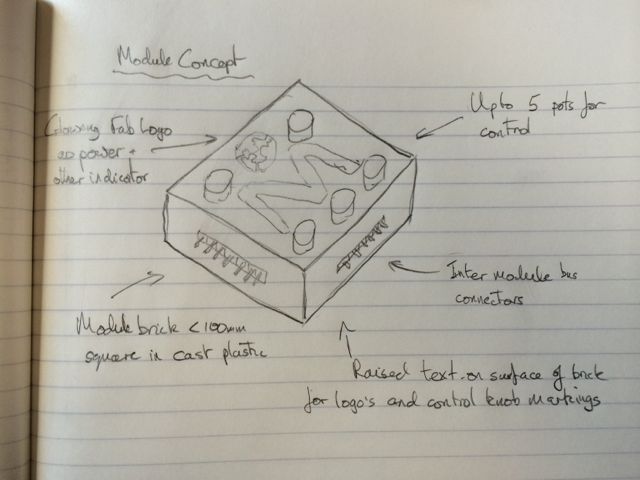
Each module is intended to be approx 70mm to 100mm square, in a
colourful molded plastic case, with connectors on the edges and
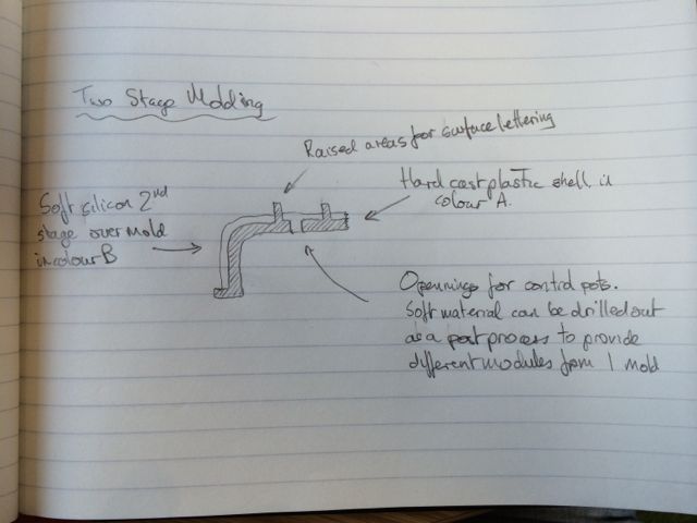
control knobs on the top. It would be good if the case molding
was a two stage process, the first as a hard plastic, the second
then soft silicon over molded in some areas to allow hard plastic to
show through forming control decals and logos. This would also
give a nice 2 colour and soft textured finish.
I'd like to implement one standard 'bus' connetor on all modules so
that any module can be connected to any other in any order.
All communications between modules will be digital. This
connector would carry the following signals:
- +5v - All modules will be powered from a single external power
source.
- GND
- Clk -There will a single synchronous clock generated from the
power module for all digital comms between modules. This
saves us having to recover separate clocks from each data stream
and deal with jitter for modules that have multiple data
sources.
- Audio Data - Depending on the connector gender this is either
data into or out of the module.
- Control Voltage Data - A digital representation of the control
voltage from the input device.
- Gate Voltage Data - A digital representation of the gate
voltage from the input device.
- Reset line? - To allow ISP on this connector?
- Sync line? - To mark the start of a new frame of data as SPI
has no word start condition and SPI clock will be generated
centrally.
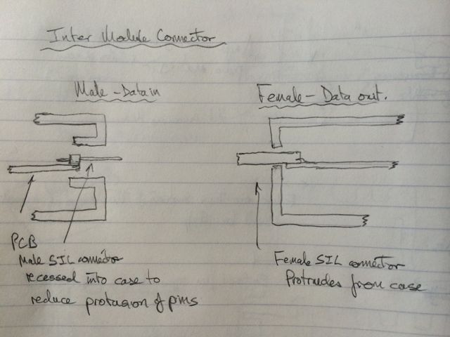
I propose to use a 8 pin SIL header at the edge of each module to
provide this bus. Male connectors will be signals into the
module, female connectors will be signals out. The connector
should be designed so that ISP pins are available to ease
re-flashing.
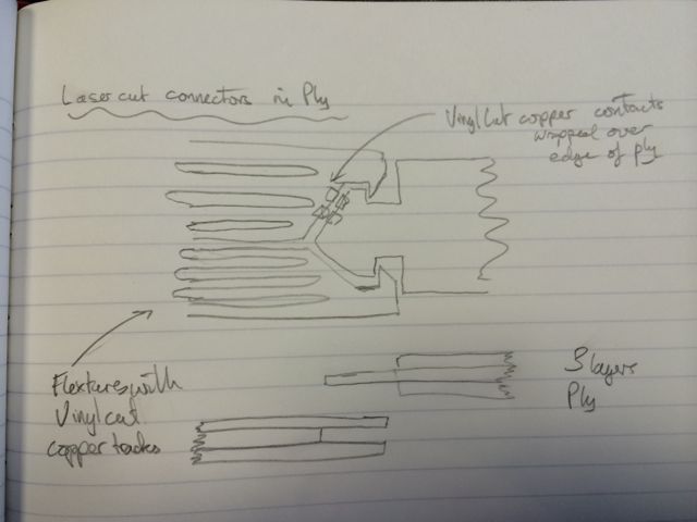
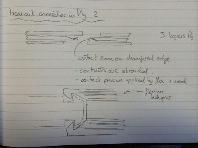
Connector Concepts - Part 2
I've had difficulty sourcing SIL connectors in the time frame for
the final project, so Initially I plan to use IDC headers and
cables. Moving on I plan to make my own connectors from layers
of 3mm ply and vinyl cut tracks.
16.05.2 Audio Data Protocol.
It would be nice to use an existing standard to transport the audio
data between the modules. This would allow the modules to
directly drive off the shelf external audio equipment such as HiFi
Amps etc.
Initially I thought of S/PDif or AES3,
but both are overly complicated for this simple task. Next,
although it's not widely supported as an external audio interface on
devices I considered using a slightly modified IIS for the inter
module comms. The modification is simply to remove the 'word
clock' line as we'll only be dealing with mono audio.
Initial intention is that audio data will be sent as 16bit mono at
44.1KHz sample rate, but this gives us a roughly 0.7MHz bit rate
from each data stream which would leave no time for DSP activity if
all serial handling is performed in software. So for this reason
I've decided that to keep audio quality by using high data rates I'm
going to need to use the SPI serial hardware in the AVR.
Obviously this only gives me one input and one output per
module. For modules requiring more input channels such as
mixers, the options are to implement extra serial interfaces in
software or move up to the ATMega range which has a second SPI
interface.
See 16.05.7 below for some limitations that may be
encountered. The data clock will be generated centrally by the
power module.
16.05.3 Control Voltage and Gate Data Protocol.
Initial concept is to send the data in a similar way to above but
sent at 8bit and 1/8th of the SPI clock, allowing bits to be read in
software from these lines on each SPI word complete. CV and
Gate would each be sent on a separate serial line. However
this would require more AVR pins and more CPU clock cycles to
implement as it would have to be a software serial interface.
Second concept is to send one serial data stream containing both CV
and Gate. 12 bit CV, 1 bit gate, 3 bits spare in a two byte
frame at 1/8th the bit rate of the SPI clock. The 1/8th bit
rate allows us to sample the software serial line in the SPI byte rx
irq routine, saving irq function prolog / epilog time.
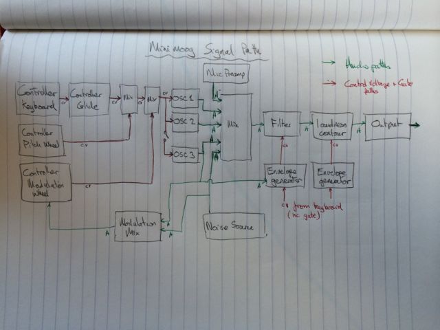
16.05.4 The Signal Path in a Real Minimoog.
Diagram of a simplified basic signal path in an original
Minimoog. This has been used to decide on module requirements
etc. for my synth.
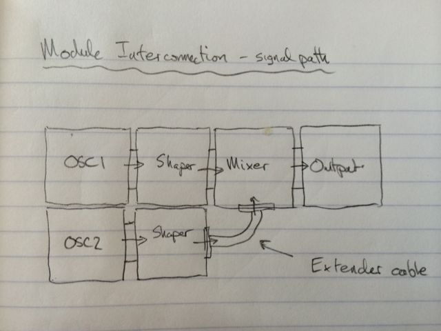
16.05.5 My Signal Path Concept.
The intention is that the signal path in my project will be
'created' as required by the user connecting modules in different
orders. Some modules would have inputs on multiple
edges. Whilst it is envisaged that the modules would connect
directly to one and other, it may also be required to use bus
extender cables between modules that can't physically be next to
each other.
Each module will support up to 5 control knobs. All will be
10K variable resistors, however some will be used as function
selectors rather than analog controls. Switches in the
original Minimoog will be replaced by the ability to add / remove
modules.
16.05.6 The Module Functions.
A List of the possible modules.
Those required to be able to demonstrate basic functionality:
- Power - Also generates serial data clock for all other
modules.
- Output - Converts the digital audio data stream into a
headphone / line output.
- Oscillator - With multiple waveform shapes.
- Keyboard - Either laser cut keys or a step response slider
from back to back triangles.
Those that would be good to have for a basic fun synth:
- Mixer - Three inputs.
- Filter - Frequency ADSR contour.
- Shaper - Amplitude ADSR contour.
- Power Output - with built in power amp and speaker.
Extended modules for even more fun:
- Portamento - insert after input device.
- CV Splitter - allowing us to send CV from a controller to
multiple devices.
- Pitch / Modulation wheels.
- Noise generator.
- Theremin input device.
16.05.7 ATTiny Limitations.
Likely problems due to limitations in the ATTiny will be:
- Lack of processor power to deal with incoming data streams and
DSP functions at the same time.
- Lack of FLASH to store lookup tables for accurate signal
generation.
- Lack of RAM to get required sample depth for DSP functions.
If these problems occur then the sample size and sample rate will be
reduced until either a workable system is produced or the sound
quality is so poor as to be unusable.
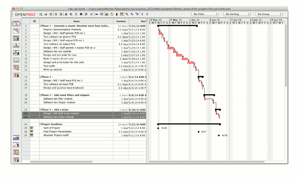
16.06 Project Plan.
Project time line below shows a snapshot of my plan as of Wednesday
21st May, OpenProj file here
is continually updated during the project. I'll keep this
project file in Mercurial and updated during the course of the
project. It's just doable for final presentation day on 4th
June. Any errors will involve working evenings and
weekends. I've split the project into separate phases, at the
end of each phase there will be a demonstrable system, slowly
growing more complete as the phases progress. By the end of
the 1st phase all of the processes I will use will have been
demonstrated bar laser cutting and vinyl cutting. These will
be added in the second phase.
16.06.1 Phase 1.
This phase is the basic set of work that I must complete to have a
project that passes Fab Academy. It's designed to cover all of
the skills required and just make a basic sound from a pair of
modules.
Get a basic oscillator module and output module built so that I can
network them together and generate sound. Will also need to
use one of the oscillator modules as a power and clock module.
These should be in a nice cast plastic case and should have nice 3D
printed knobs on the controls.
16.06.2 Phase 2.
This phase would be nice to get done before the project
presentations as it will add an input device and make the synth a
playable instrument.
Add an input device such as a keyboard.
16.06.3 Phase 3.
This phase will add some basic modules that will make the sounds
from the synth more interesting.
Add filters and shapers. These modules are only software
changes from the basic generic oscillator module.
16.06.4 Phase 4.
This phase will add a mixer allowing the synth to make much more
complex sounds.
16.06.5 Other Phases.
Add many more input devices...
Make a dedicated power and clock module...
16.07 Machines and Processes.
I'll be using the following machines and processes:
- Mercurial to keep all revisions of my design files and source
code.
- OpenProj to keep track of task list.
- Eagle for PCB design.
- Modela for PCB manufacture.
- Vinyl cutter possibly for copper touch pads on input device.
- 2D CAD for frame of input device.
- Laser cutter for frame of input device.
- 3D CAD for case on modules.
- Shopbot for mold for case on modules.
- Casting for case of modules.
- 3D CAD for knobs on trim pots.
- 3D printing of knobs for trim pots.
- Programming for AVR's on modules.
- Networking between the modules.
16.08 Materials and Costs.
I plan to use as much from the inventory as possible. I will
need to order:
- 8 way SIL connector sockets. Or alternative inter module
connectors.
- Pots for control knobs (re-stock the ones in the inventory as
we're out).
- ... That's about it.