SENSING FOLDING STRUCTURE
For the project I need to implement a sensor that can keep track of shape changes happening on a soft surface. I am not sure yet what shape change will be, but generally speaking the surface will go from flat to bent/folded. Therefore I need to identify a sensor that can give me a degree of values indicating when the surface is flat, slightly bent or touching.

I identified a variety of options:
- hand-crafted switch (0/I)
- transmit/receive capacitance
- step response capacitance
- sensing variable resistance of a material produced when bent or stressed
- hall sensor
I got started by investigating capacitance as a potential sensor, to understand if the changes in distance between 2 copper electrodes influences the time it takes them to charge and therefore gives me real time information about the transition of the material from flat to 3d.
Capacitive sensors are very sensitive to human presence and positioning next to other electronic devices... This sensitivity is both an interesting feature and a challenge, because it means their values can never be isolated. It would be difficult to calibrate the values and obtain accurate readings of the shape change since I will always 'intervene' on the surface. But I am also wondering if I could use this data to record human touch on my surface.
So I am running some tests to check the accuracy of various types of capacitive sensing systems.
CAPACITANCE 01
I started by testing with the Arduino and Arduino IDE, using the Capacitive Sensing Library standard example.
The CapitiveSense Library Demo Sketch by Paul Badger 2008 uses a high value resistor (1 to 10 megohm) between send pin and receive pin.


CODE:
#include
CapacitiveSensor cs_4_2 = CapacitiveSensor(4,2);
//CapacitiveSensor(BYTE SEND PIN, BYTE RECEIVE PIN)
// defines pin 2 as sense(receive) pin and pin 4 as send pin
// send pin can be shares with many sense pins
void setup() {
cs_4_2.set_CS_AutocaL_Millis(0xFFFFFFFF);
// turnS off autocalibrate on channel 1
// The method set_CS_AutocaL_Millis(unsigned long autoCal_millis) may be used to set the timeout interval of the capacitiveSensor function. Re-calibration may be turned off by using set_CS_AutocaL_Millis to set CS_AutocaL_Millis to "0xFFFFFFFF".
Serial.begin(9600);
}
void loop() {
long start = millis();
long total1 = cs_4_2.capacitiveSensor(30);
//long capacitiveSensor(BYTE SAMPLES) requires one parameter, samples, and returns a long containing the added (sensed) capacitance, in arbitrary units. capacitiveSensor keeps track of the lowest baseline (unsensed) capacitance, and subtracts that from the sensed capacitance, so it should report a low value in the unsensed condition.
The baseline is value is re-calibrated at intervals determined by CS_Autocal_Millis. The default value is 200000 milliseconds (20 seconds).
Serial.print(millis() - start); // check on performance in milliseconds
Serial.print("\t"); // tab character for debug window spacing
Serial.print(total1); // print sensor output 1
Serial.print("\t");
delay(10); // arbitrary delay to limit data to serial port
}
This example is similar to Neil's step-response example because they both compare values between 2 pins. In Neil's example the pin is charged, and the values are recorded as 'up' values, then is discharged and the values are recorded as 'down' values. However results seemed vary unreliable.
VARIABLES:
- Resistor size that affects sensitivity of the pad. Larger resistor values yeld larger sensor values.
- Copper trace size
- Influence of the user's capacitance
- Capacitive sensing has some quirks with laptops unconnected to mains power. The laptop itself tends to become sensitive and bringing a hand near the laptop will change the returned values.
CAPACITANCE 02
Using an Arduino for initial proof of concept.
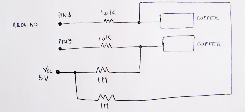
Based on Santi's suggestion I tested another capacitive circuit, that has been used in Santi's final project and in this instructable.
From the instructable:
- The circuit and code set the pin to output mode.
- Write a digital "low" to the pin. This means both sides of the capacitor are grounded and it will discharge.
- Set the pin to input mode.
- Count how much time it takes for the capacitor to charge by waiting for the pin to go "high". This depends on the values for the capacitor and the two resistors. Since the resistors are fixed, a change in capacitance will be measurable. The distance from ground (your hand) will be the primary variable contributing to the capacitance.
This example did seem to give me slightly interesting values between copper tape electrodes.
CAPACITANCE 03
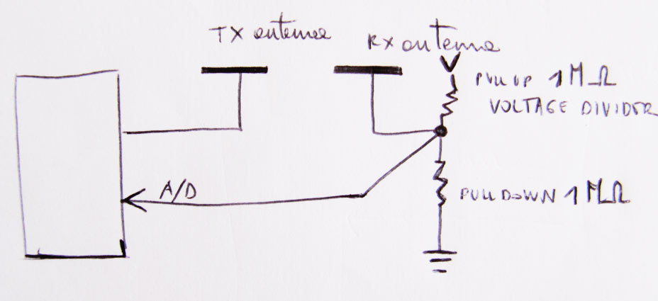
Using rxtx board designed in week 10. I then tested if Neil's rxtx circuit could sense the 2 copper electrodes getting closer. From the tests it seems that there is not much difference in proximity (values 8to30), only a significantly higher value when the 2 copper traces (rx and tx) are in contact (values around 36000).
CAPACITANCE 04
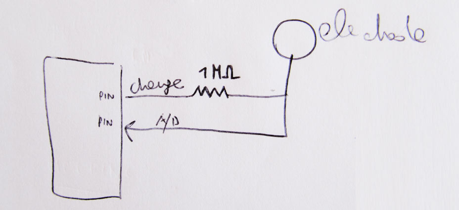
Using the step response board designed in week 10. I then tried to understand if Neil's step-response (cirucit that I made in week10 but didn’t use) could work. I adapted Neil's step response code written for attiny 45 to the attiny 44. It's a single ended sensor in ADC1/PA1. I connect only one copper trace to a pin and got closer to it with another trace, to see if the sensor would record a range of values. I obtained slight variations, but still values are fluctuating a lot and are very unreliable.
TESTING RESISTIVE THREAD
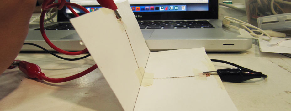
Looking for other solutions I had a look at Plusea's diy bend sensors made of resistive conductive thread.
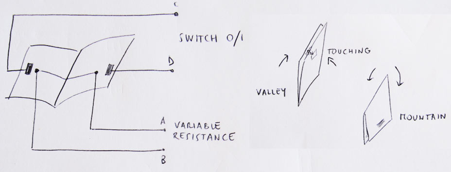
I attached a piece of thread to creased paper and connected the two ends to a multimeter to test the change in resistance, both when the thread is stressed and when relaxed.
I obtained a quite reliable range for both types of movement.
NOTES:
- Center of hinge must be 'blocked', attached to substrate
- Probably needs calibration, that could be done by having a simple 'switch' on both sides of the hinge, to record the values
- needs semi-rigid structure
- needs very precise length of thread
HALL EFFECT SENSOR
But the most reliable sensor is the magnetic sensor.
I borrowed Taichi's magnetic sensor attiny44 board to do a quick initial testing.
I wrote a basic Arduino sketch, using analogRead to get the sensor values.
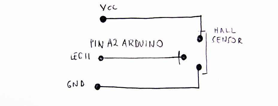
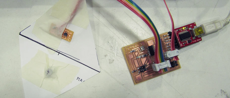
I attached the Hall sensor to one side of the hinge, and a small magnet on the other side.
The values are very reliable. In this test, the flat surface would always be 514, and gradually increase the values (or decreased if the magnet was flipped), till the magnet is almost in contact with the surface.
NOTES: - the sensor doesn't know if it is in mountain or valley configuration so I will have to find a solution to this !!!!!!!!!!!!!!!
ORIGAMI TESTS
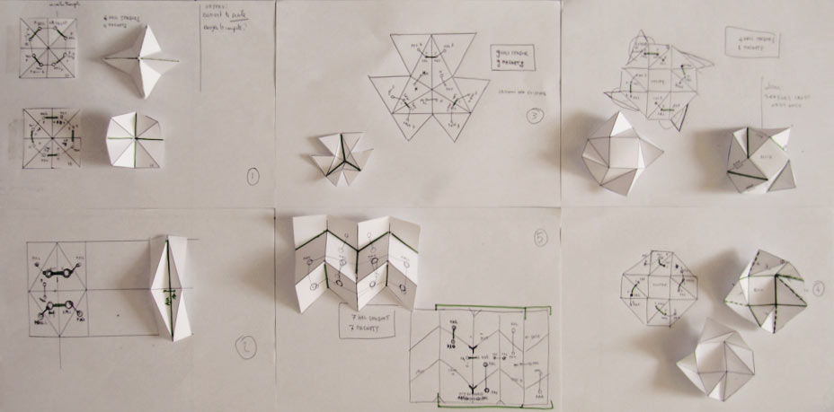
I then started making some simple origami shapes and trying to work out where I would place the hall sensors and the magnets on each of them.
BOARD DESIGN
I designed a board (attiny44 processors) that can control up to 8 hall sensors. The idea is to start testing out the sensors, how I can detect mountains and valleys, understand how the magnetic field of each magnet influences the readings...
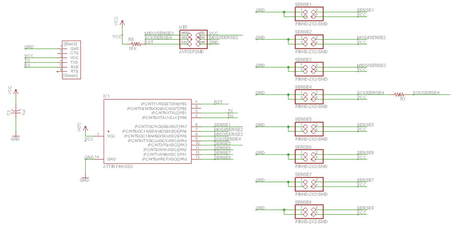
ATTINY44 LEGS:
VCC
PB0> rx (actually used as tx in the code)
PB1> tx (actually used as rx in the code)
PB3
PB2>
PA7> sense1
PA6> sense2
GND
PA0> sense8
PA1> sense7
PA2> sense6
PA3> sense5
PA4> sense4
PA5> sense3
1 x ATTINY44SU
1 x 3X2 PIN HEADER (ARVISP SMD)
8 X 2X2 PIN HEADER SMD
1 X FTDI SMD HEADER
1 x CAPACITOR 1 uf
1 X 10 k RESISTOR RES-US1206FAB
1 X 0 Ohm RESISTOR RES-US1206FAB
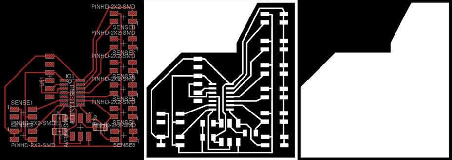
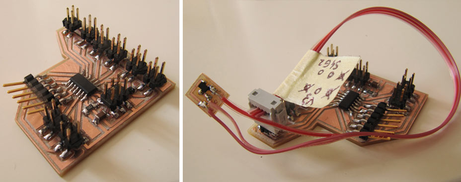
BOARD TESTING
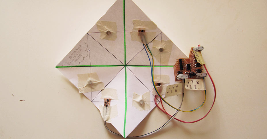
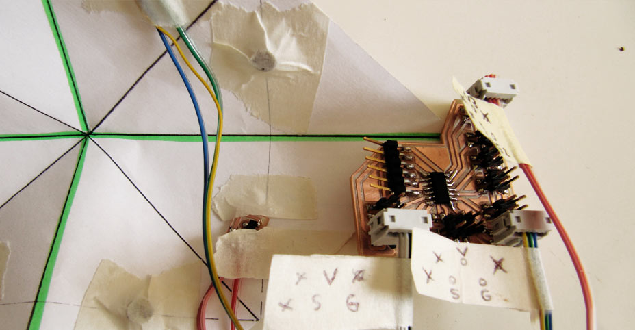
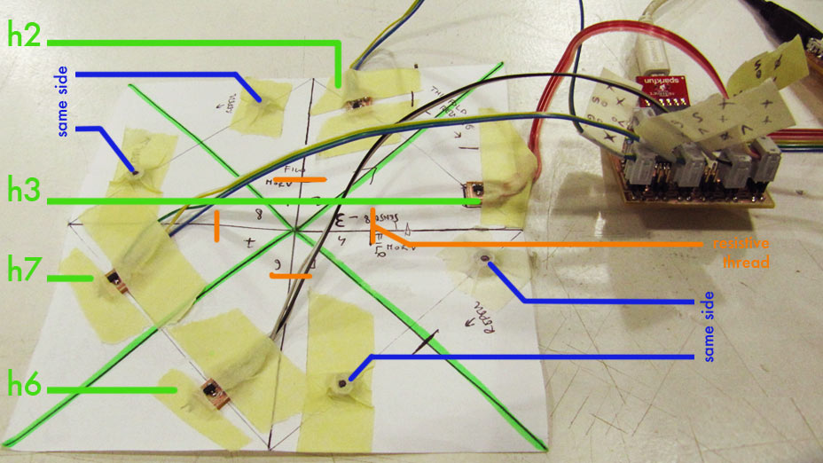
Testing out the sensors I discovered that:
- they work better as pairs of hall sensor > magnet
- in the single flap, the sensor doesn't 'recognise' mountains or valleys, because the orientation of the magnet is always the same
- therefore I am thinking of adding the resistive thread to the system, to compute the mountain/valley: when the thread is stressed I will get different values from when it is relaxed
- the magnet has to be placed to perfectly match the center of the hall sensor otherwise I will get fluctuating values
- the magnets/hall sensors have to be placed close to the hinge to get a better range of values
- the values obtain increas exponentially, that will have to be addressed in the future coding
- the 'mountain' flods as displayed in the current sensor configuration should be kept open as much as possible to avoid interference between the magnets
- the magnets are 'paired' to repell each other in the current configuration to avoid the structure to collapse due to their attraction
FRAME FOR 3D PRINTING
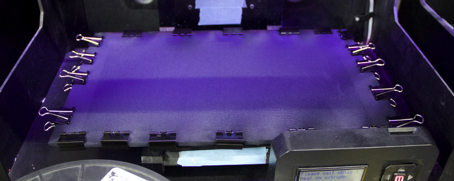
I started working on the hardware part of the project. I initially inteded to 3d print on fabric surfaces and take advantage of the tension of the material while printing to obtain 3 dimensional changes once the surface tension was released.
I designed a frame that could snap to the Makerbot Replicator 2 bed and allow me to stretch the fabric and fix it to the base.
I used bulldog clips on the side, and I needed to remove the metal parts to prevent collision with the 3d printing head moving on the bed.
MATERIAL:
5mm Acrylic sheet
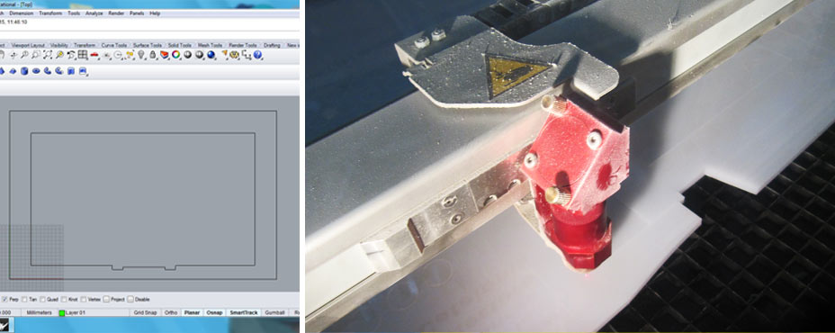
file cut frame working
CUTTING SPECS:
On Trotech:
Material: Plastics, acrylic_5mm
Cut(red lines): P 100, V 0.60
On Epilog:
Material: Poly(methyl methacrylate) 5mm / Plexiglass
Vector only
Power: 95%
Speed : 10%
FABRICS DETAILS
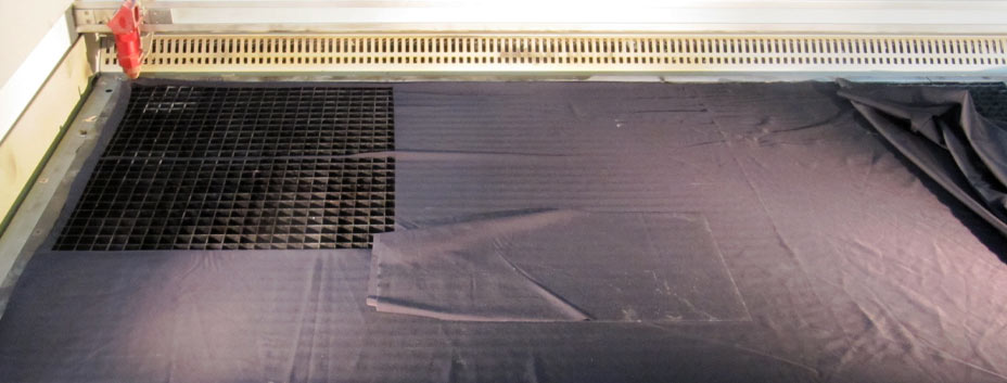
MATERIALS: Fabrics:
- polyester/lycra/cotton mixes in different thicknesses
- powermesh fabric
CUTTING SPECS:
On Epilog:
Speed: 70%
Power: 50%
Frequency: 2500
3D PRINTING TESTS
PROCESS:
- Attach tape onto 3d printer bed
- stretch fabric, attaching it with bulldog clip to frame
- place frame onto bed
- calibrate 3d printing bed
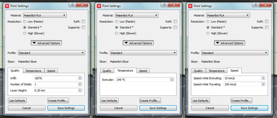
3d printing specifications for NinjaFlex:
3d printing specifications for PLA:
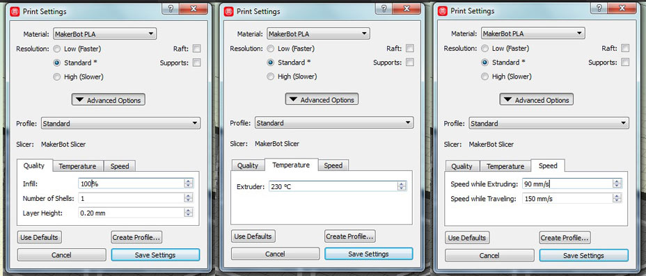
Unluckily 2 out of the 4 materials chosen melted under the temperature of the extruded material.
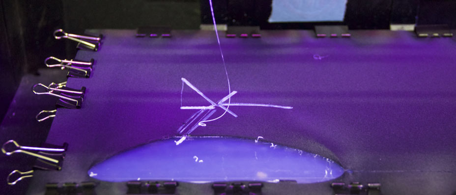
Problem:
I was trying to print 2 materials with the single extruder.
When exporting the files from the Makerbot software, I checked the Travel Moves in printing preview and realised that, after having printed with the first material,although the 2 material forms were complementary, the 3d printing head would have bumped into the 3d pattern trying to complete the second shape.
- I therefore tried to rearrange my designs in a way that would prevent this
- I printed one test at a time.

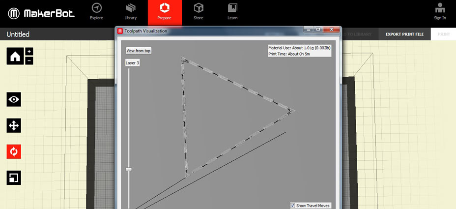
Tests:
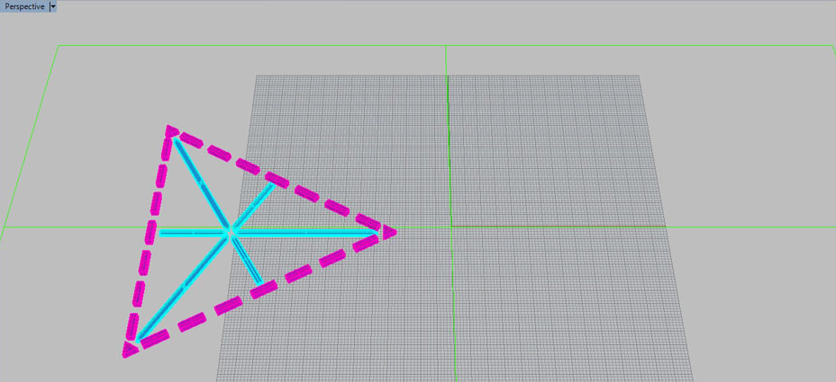
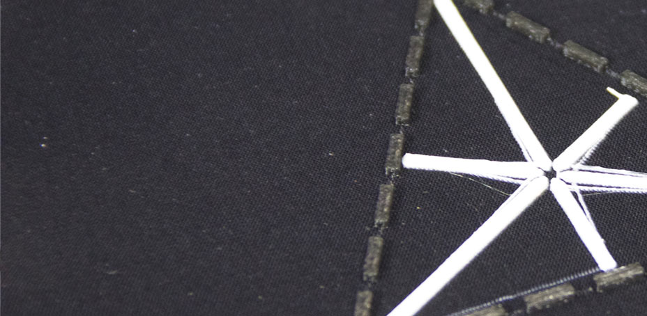
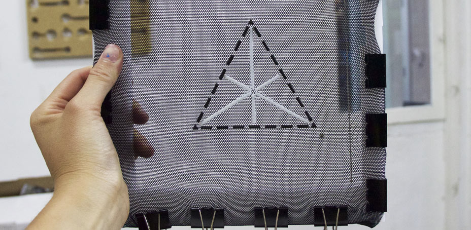
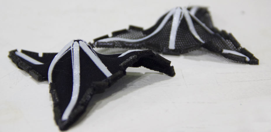

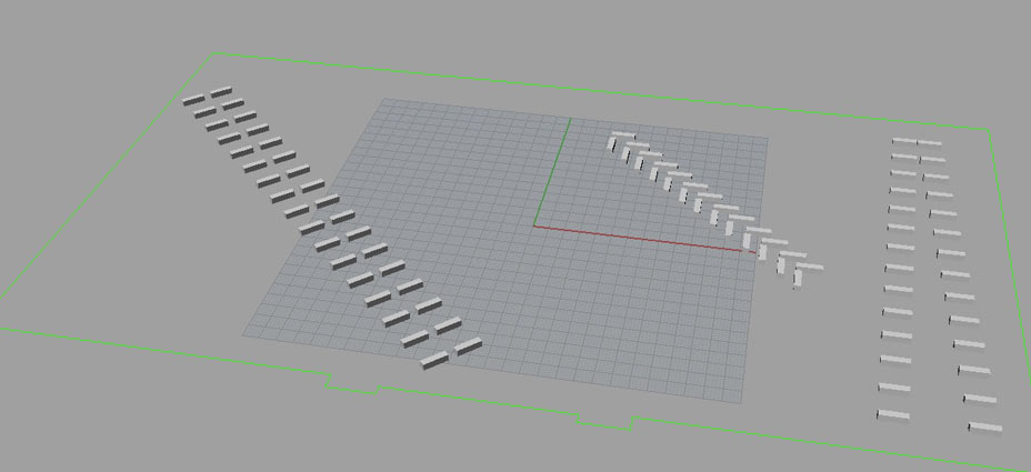
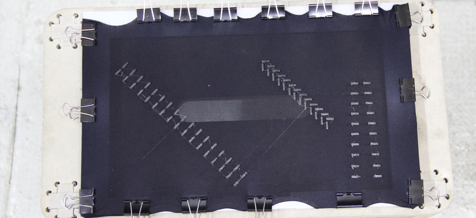
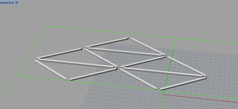
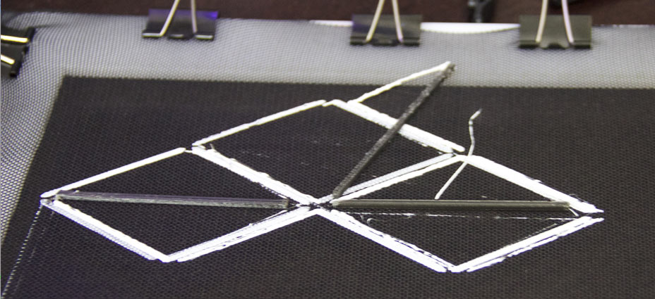
At this point I realised that in the timescale of the project I wouldn't have been able to achieve the intended results.
> The process of printing turned out being very time consuming
> Elasticity of the materials available was not enough for obtaining the effects. Previous tests (documentation from week 5) had been carried out on tights-type material, with a considerably higher percentage of lycra. Fabrics of this type could not be sourced.
> The extruded materials didn't stick properly to the textile base
> Printing with 2 materials would have been impossible for elaborated shapes, and would have been only possible by deconstructing the design and reconstructing the finished piece.
NEW PLAN
At this point I identified textiles composites as new potential technique for production of a prototype of a surface with both rigid and flexible characteristics in origami-like mannor.
I therefore identified areas to develop:
- compositing process development
- identify what wires/printing techniques to use to connect on-surface sensors to microprocessor
- choose wires to microprocessor connection
- solder/fix hall sensor to copper traces
- encapsulate hall sensors and apply to textile surface
- create safe connections between wires going to microprocessor and hall sensors
- encapsulate magnet and apply to textile surface
- where to place sensors: top or bottom of prototype
HALL SENSORS + HOUSING
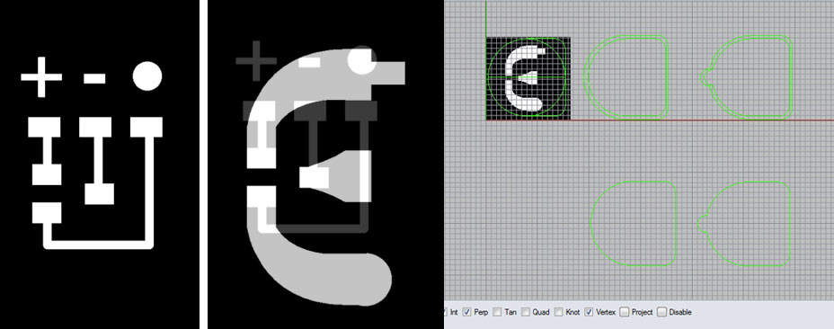
1. Hall sensor traces design:
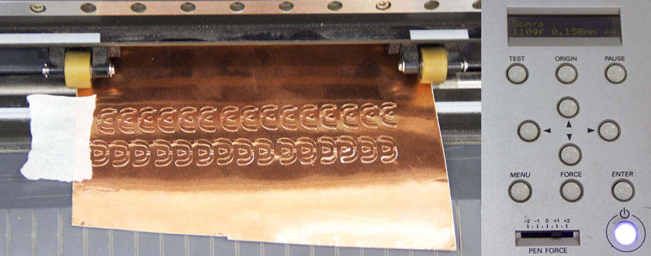
I redesign the sensors traces to be wider, to allow to be easily vinylcut and weeded.
2. Vinyl Cut Traces
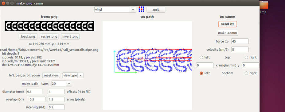
3. Base for traces:
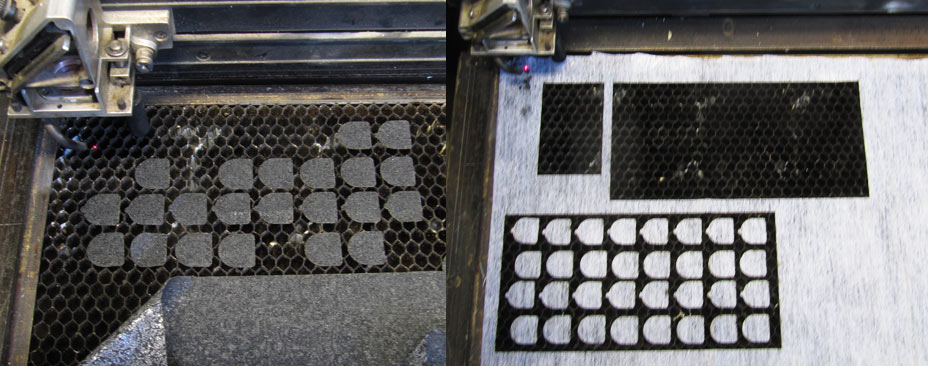
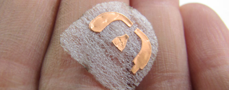
I chose to work with a thin self-adhesive fabric, as a base for the copper traces. Its design followed the shape of the sensor traces, leaving space for soldering wires to the ends of the traces.
MATERIALS:
Adhesive fabric
CUTTING SPECS:
On Epilog:
Speed 80%
Power 30%
4. Soldering hall sensors:
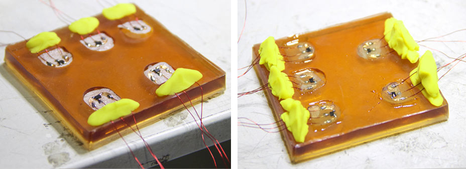
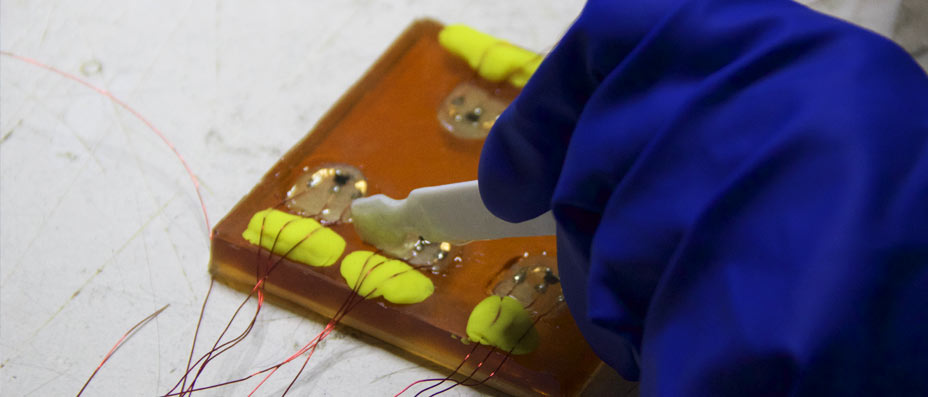
5. Casting sensors:
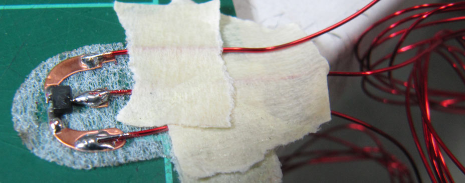
I was looking for a resin to work as :
- transparent sensor housing
- to prevent the thin wires from breaking at connection point with sensor traces
- to prevent short circuits between sensor legs since they were so close together
Not chosen - casting in 2 parts epoxy glue (sets in 5 mins):
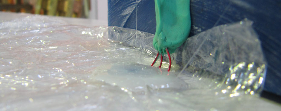
Not chosen - casting sensors directly on fabric in 2 parts epoxy for composites (set in 6 hours)

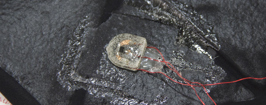
Initial designs of 3d mold for casting sensors, and lasercut mold on 2.5 mm Acrylic:
MATERIAL:
2.5 mm Acrylic
CUTTING SPECS:
On Epilog:
Speed: 15%
Power: 60%

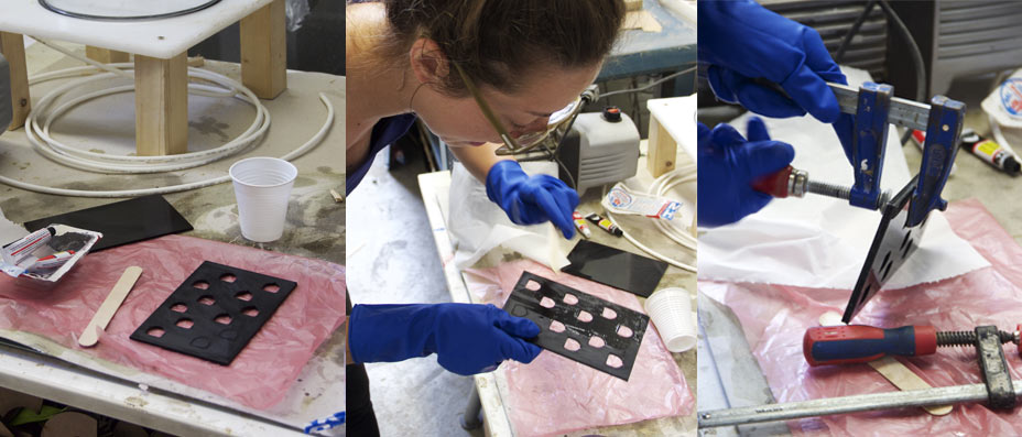
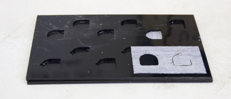
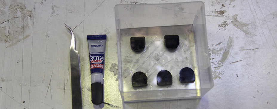
Since I realised that epoxy was not the best material to use, I looked for other options. I tested Araldite 2 parts glue and superglue on silicone molds, to find the best casting material.
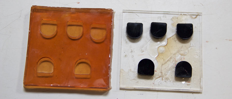
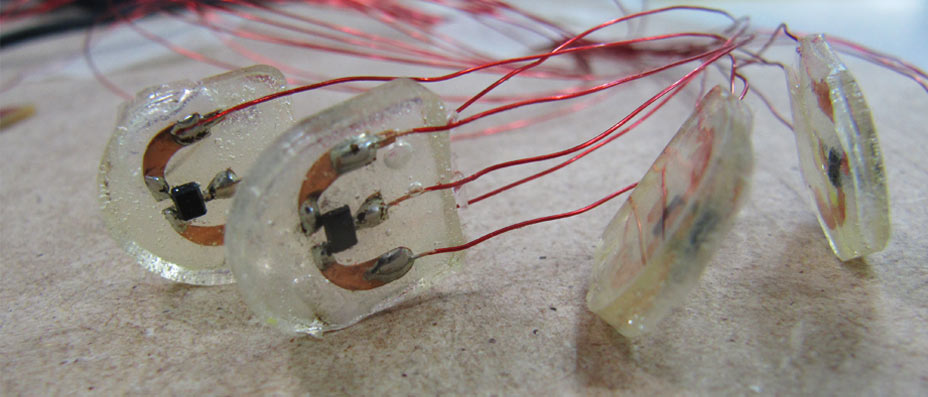
(None of the 2 materials would have worked with the 2d lasercut mold, they would have binded to the acrylic.) I decided to work with Araldite 2 parts glue, since after curing for about 12 hours on a silicone mold material, it would demold really easily from the rubber and remain transparent.
I quickly produced a mold from lasercut acrylic applied to a plastic box to cast 5 sensors at a time.
MATERIAL:
Araldite 2 parts
Curing time: 12 hours
COMPOSITE TESTING
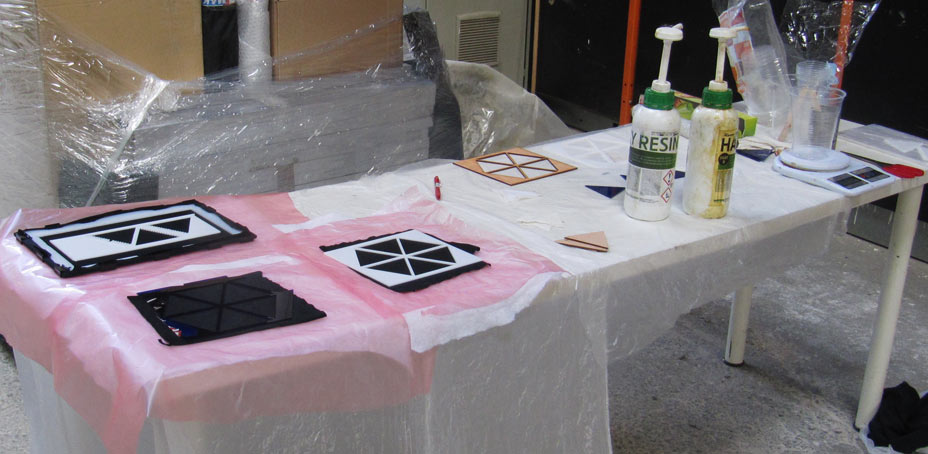
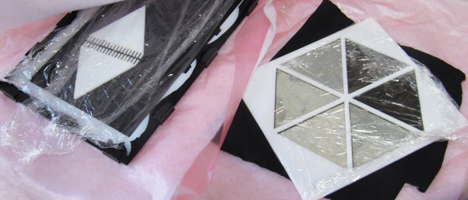
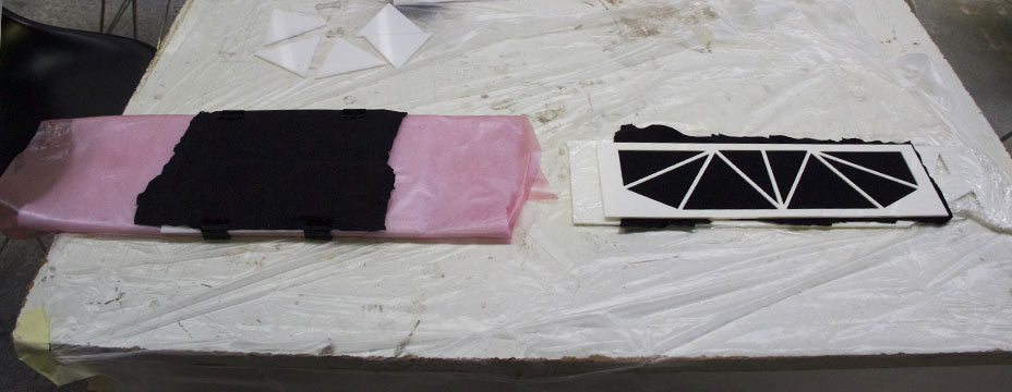
Compositing process TEST 1:
- 1 and 2 layers of fabric applied on textile substrate
- 2.5 mm acrylic lasercut shapes applied on textile substrate
- 2 mm veneer lasercut shapes applied on textile substrate
- epoxy only
- 6 hours in vacuum press
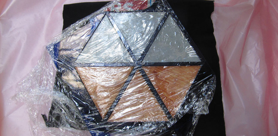
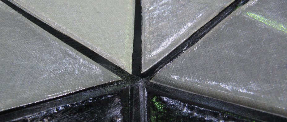
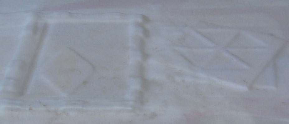
OBSERVATIONS:
> Obtaines great finish by peeling off acrylic shapes from fabric after vacuum press
> 2 layers of fabric produced very stiff features
> I managed to preserve in most of the tests the hinges from epoxy glue penetration



Compositing process 2:
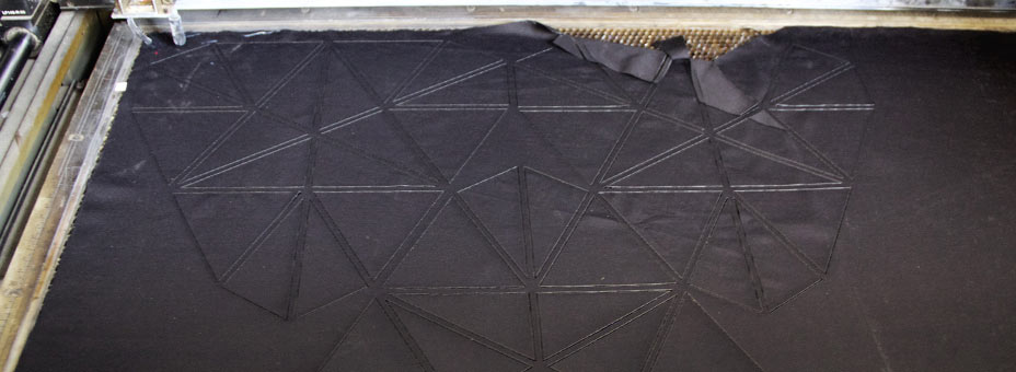
- vynilcut 'frame' applied on hinges points to preserve fabric from epoxy penetration
- 2.5 mm perspex lasercut elements covered in glue and applied on surface
OBSERVATIONS:
> although on top side the textile was preserved from the glues, on bottom layer it spread everywhere!

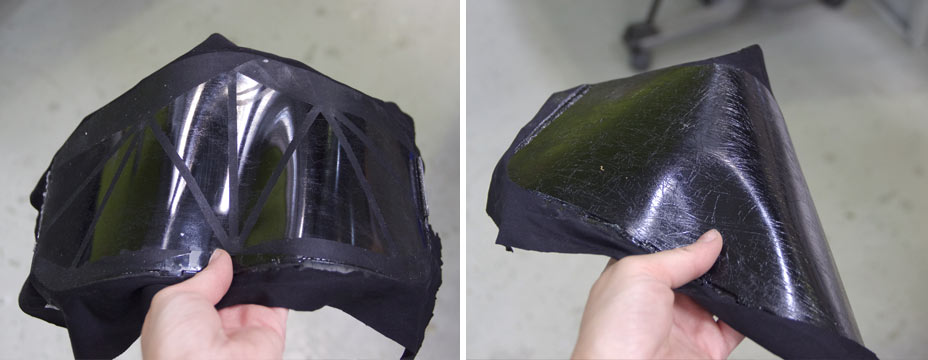
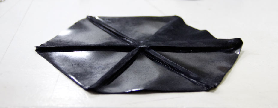
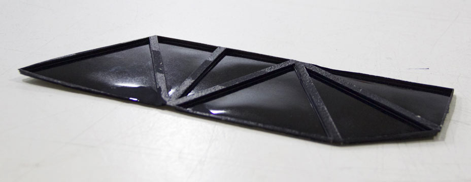
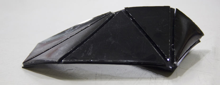
Compositing process 3:
> tried to raise the hinge from the compositing elements, but experiment failed because by raising the hinges I actually created rigid features in the 3rd dimension
> which provoked problems in rigidity of the structure


Compositing process 4:
> failed because too much epoxy penetrated in hinges and flattened effect
MATERIAL:
Perspex 5 mm
NOT FIT TO LASER CUTTING, IT CREATE FLAMES!!!
CUTTING SPECS:
On Trotech:
Acrylic 8 mm specs
Power: 90
Velocity: 0.6
Frequency: 7000


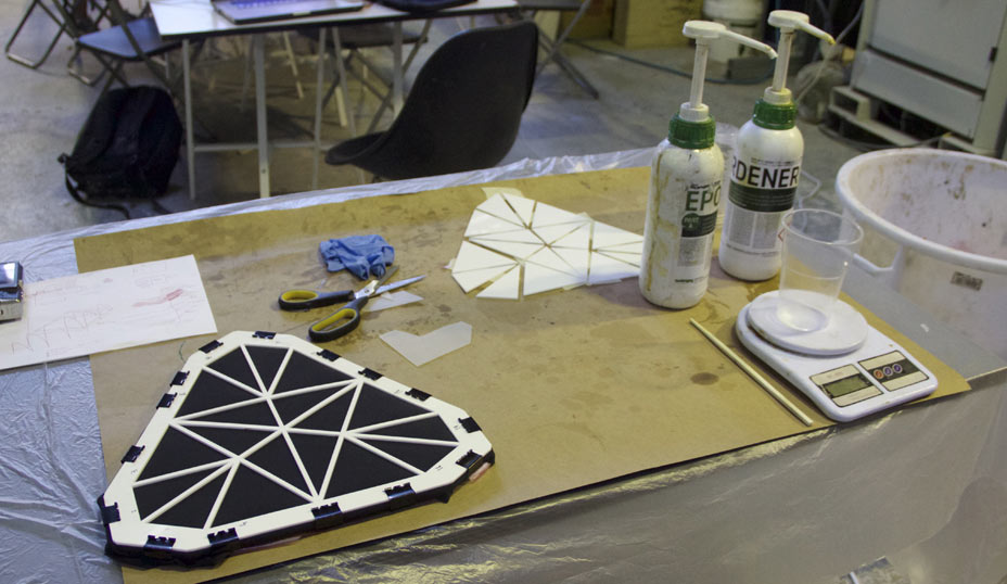

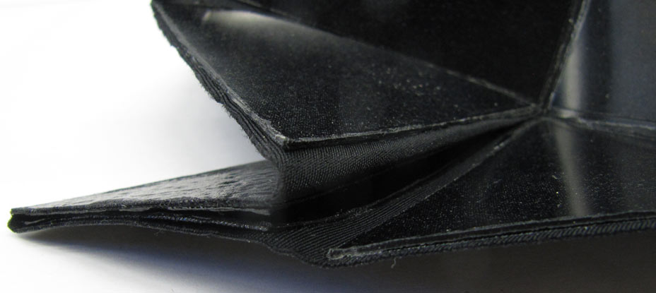
Final compositing process:
I needed to find a way to absorb the epoxy during the production of the composite to prevent leakage on hinges.
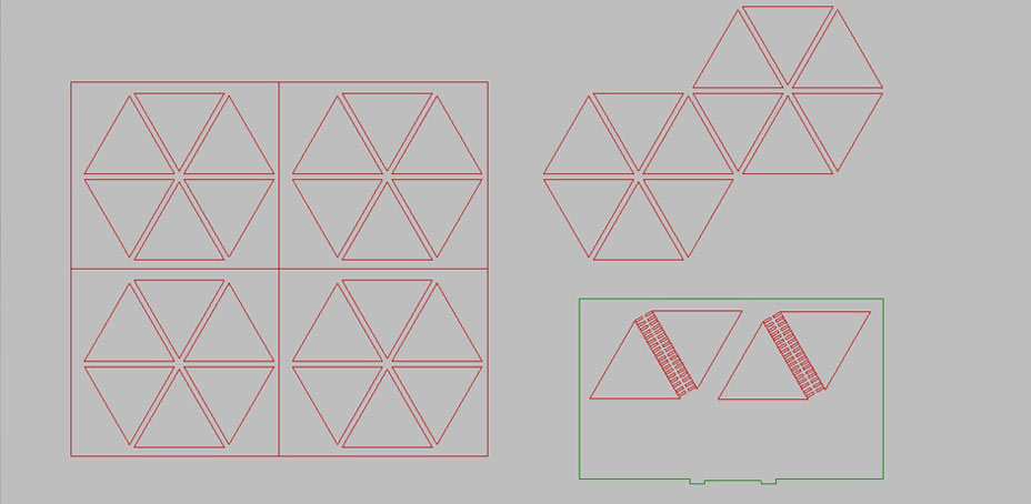
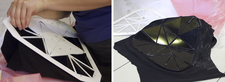
- lasercut 2xshape features
- apply epoxy to them
- apply features on surface
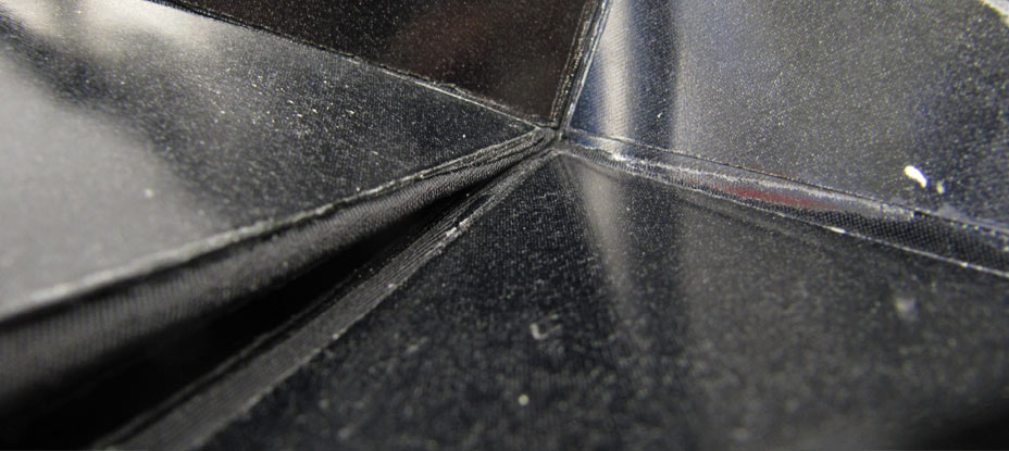
- press with acrylic to obtain lucid finish
OBSERVATION:
Success!!! The frame was preserved, the composite areas were stiff and the finish perfect.
(I refined the result by hand,cutting the extra material with a sharp craft knife)

MOLDING MAGNETS
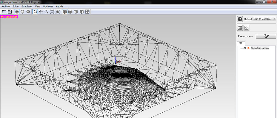
1. 3d Design of the positive mold in machinable wax:


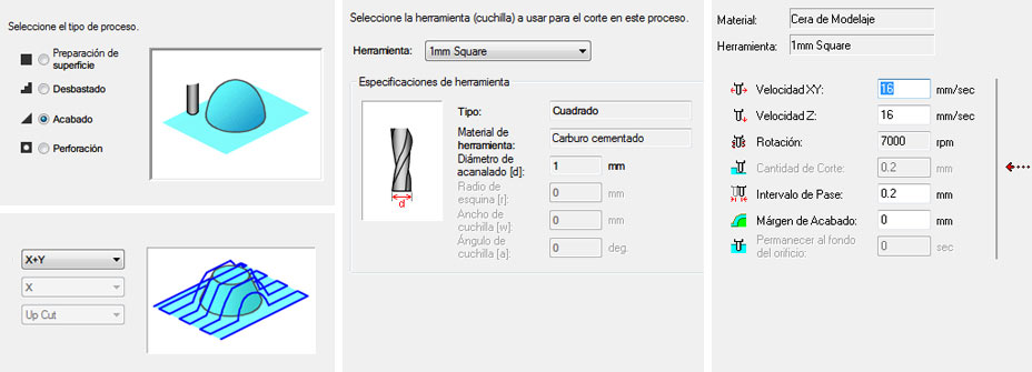
Modela Player 4 specifications:
Surface Roughing

Surface Finishing (in X and Y)
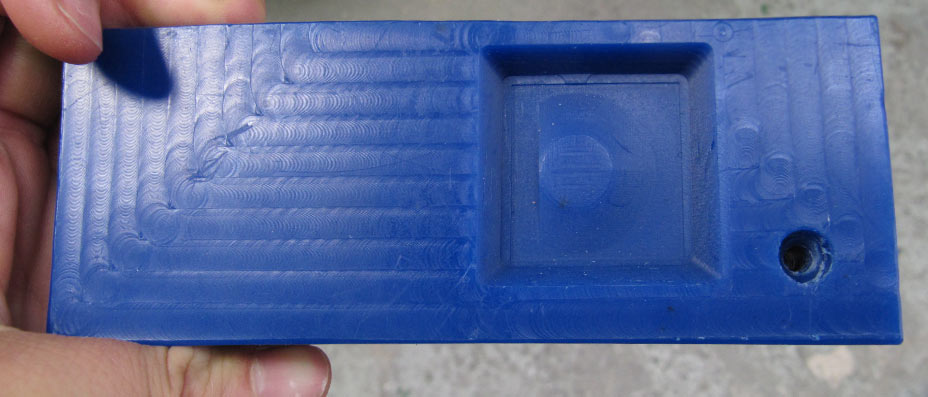
2. Casting the silicone Mold:
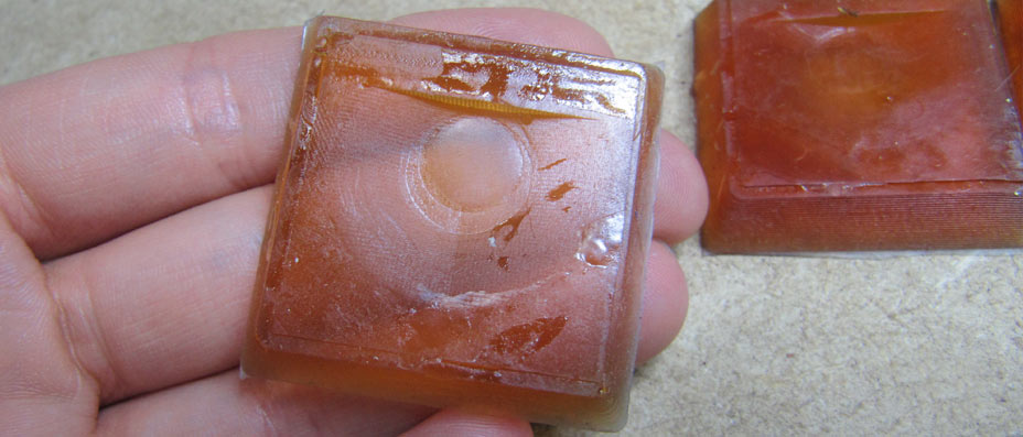
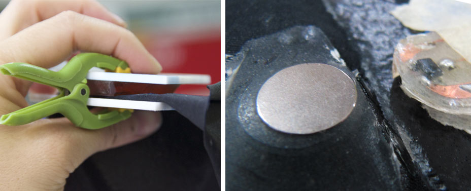
3.Casting Magnet on textile:
Vynilcut trace for positioning of magnets and sensors on hinge
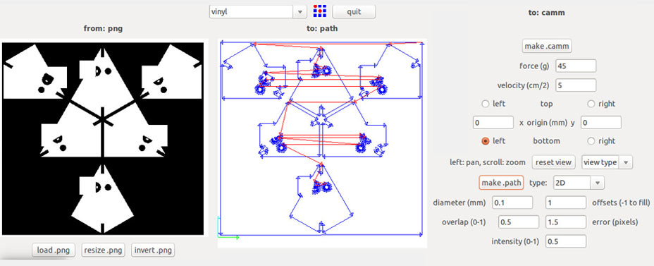
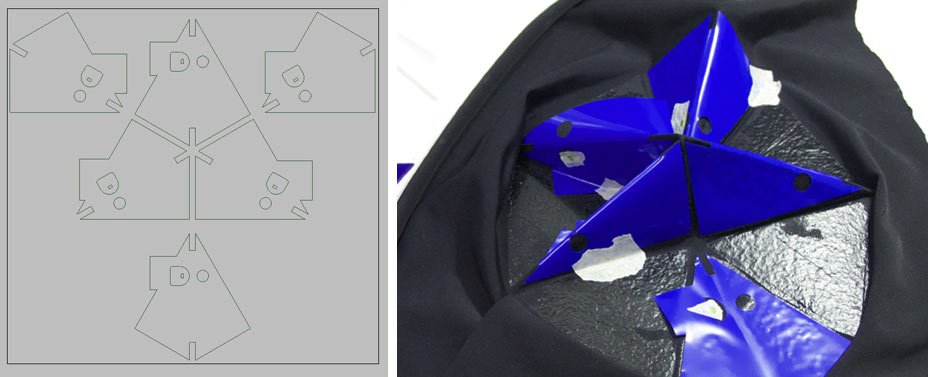
Casting the sensors in Araldite directly on fabric (preserving areas with vynil).
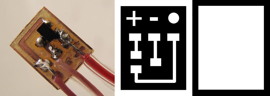
FINAL CIRCUIT BOARD
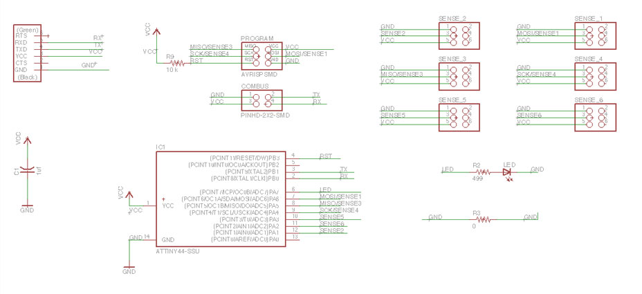
ATTINY44 LEGS:
VCC
PB0> rx (actually used as tx in the code) / LEG 2 ATTINY / PIN 9 ARDUINO
PB1> tx (actually used as rx in the code) / LEG 3 ATTINY / PIN 10 ARDUINO
PB3> RST
PB2
PA7> LED / LEG 6 ATTINY / PIN 7 ARDUINO
PA6> sense1 / LEG 7 ATTINY
GND
PA0
PA1> sense2 / LEG 12 ATTINY / PIN 1 ARDUINO
PA2> sense6 / LEG 11 ATTINY / PIN 2 ARDUINO
PA3> sense5 / LEG 10 ATTINY
PA4> sense4 / LEG 9 ATTINY / PIN 4 ARDUINO
PA5> sense3 / LEG 8 ATTINY
BOARD COMPONENTS:
1 x ATTINY 44 SSU
1 X FTDI SMD HEADER
1 x LED 1206 SMD
1 X RESISTOR RES-US1206FAB 0 Ohm
1 X RESISTOR RES-US1206FAB 499 Ohm
1 X RESISTOR RES-US1206FAB 10k Ohm
1 X 3X2 PIN HEADER (ARVISP SMD for programming board)
1 X 2X2 PIN HEADER SMD (for async serial communication between nodes)
1 x CAPACITOR 1 uf
3 x HALL SENSORS
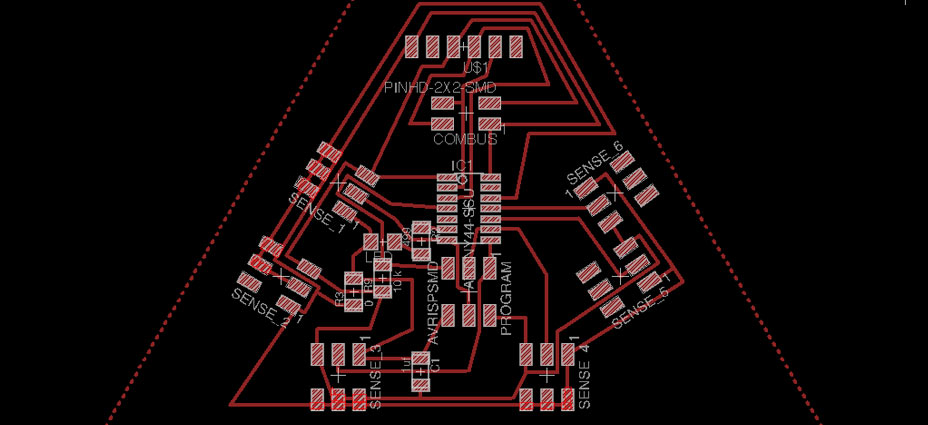
I designed the board using the 3X2 PIN HEADER component to create the traces for the connection between the sensor wires and the board. I only neede 3 out of the 6 pads, so I cleaned them up in Photoshop after having exported the PNG file from Eagle.


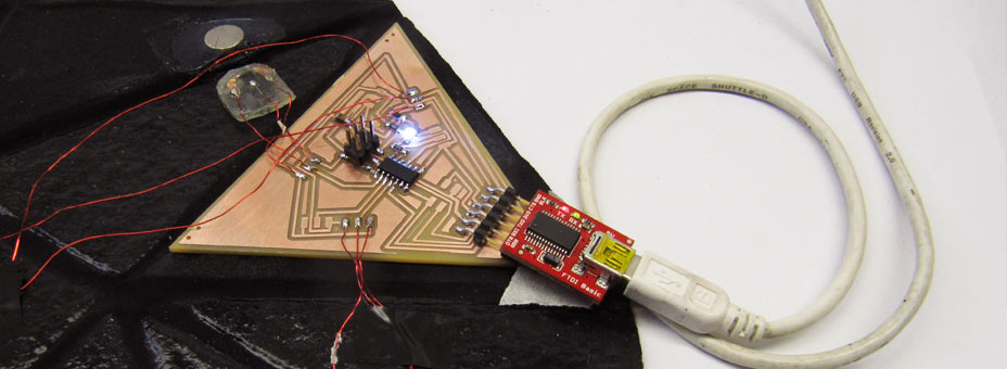
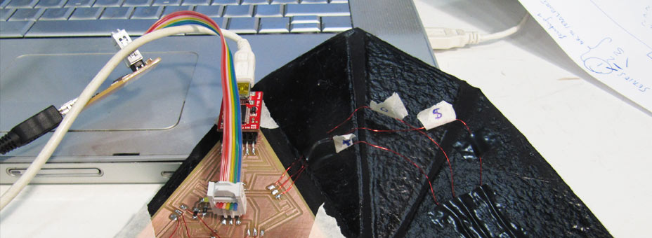
FILES DOWNLOAD LINK
HOME | ABOUT | WORK | CONTACT
Francesca Perona © 2015

This work is licensed under a Creative Commons Attribution-NonCommercial 4.0 International License
Original open source HTML and CSS files
Second HTML and CSS source
Francesca Perona © 2015

This work is licensed under a Creative Commons Attribution-NonCommercial 4.0 International License
Original open source HTML and CSS files
Second HTML and CSS source