Our main goal for this week is to show that we are able to use 2d and 3d CAD systems and are free to express our ideas with their help. So, at this page I can only tease you with some sketches from my different final pject's proposals and get you through some experiments with 2d and 3d CAD systems I've been through.
In case you get interested, you may find more information about the way of finding the idea for my final project and trace all it's transformations here. I also find the design for my fnal project closely relative to this week's subject, so here's the link. Well, let's rock!
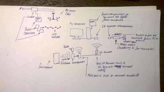
Here is the paper sketch for my first final project proposal. I wanted to make the smart-house system that woul allow to control the illumination in very modable way and also promote the way to for universal control on all the electronics (PC included) via the single remote control. It's a little too complicated for rightaway implementation, but still I like the idea.
Sure, it is a little misproportional, but still counts! There are some main systems that need to be implemented in this project. The next step would be isolating the micro-projects from this big one and choosing the way to finish them one by one.
I decided to redraw the main flow-chart using different programs and my first step in that direction is Libre Office Draw (because it is really simple). What are my impressions about that? Its maybe even too simple and it does not have all the power of working with vector graphics I am use to (I use corel draw mostly, inkscape sometimes) or maybe I just didn't get all the things about that yet. Nevertheless, thats my about 60% complete flowchart exported as jpg:

Source file is here(zip) or here(odg-file).
This simple design tool lacks some of those convinient features I wanted to get from the vector graphics editor (like snapping for example). Maybe I didn't work long enough with that to reach the full power of this feature, but it seems to me that the only snaping that is used here is:
It means that I can not snap to vertexes or tangents between the figures. Also I didn't find a way to work with layers. That was not nice, but maybe I just need to study this CAD a little harder.
Here I wanted to have a 3D-sketch for my theremin-lamp press-fit to make sure it is designed right and can be assembled. That's what I had as a reault:

I decided to try Rhino, because I had problems with 123d-design with importing the outlines I made in CorelDraw (it was crushing over and over again during the import procedure) and Rhino was something my instructor advised me to try.
That's how the Rhinoceros window looks like:

It took me some time to get used to the interface and the way it is working, but now I really like this CAD! Why?

That was a little intro to rhino. Now back to the work!
I already had the outlines drawn in CorelDraw and I wanted to import them to Rhino somehow to make 3D-models for all the parts with extrusion and then combine them.
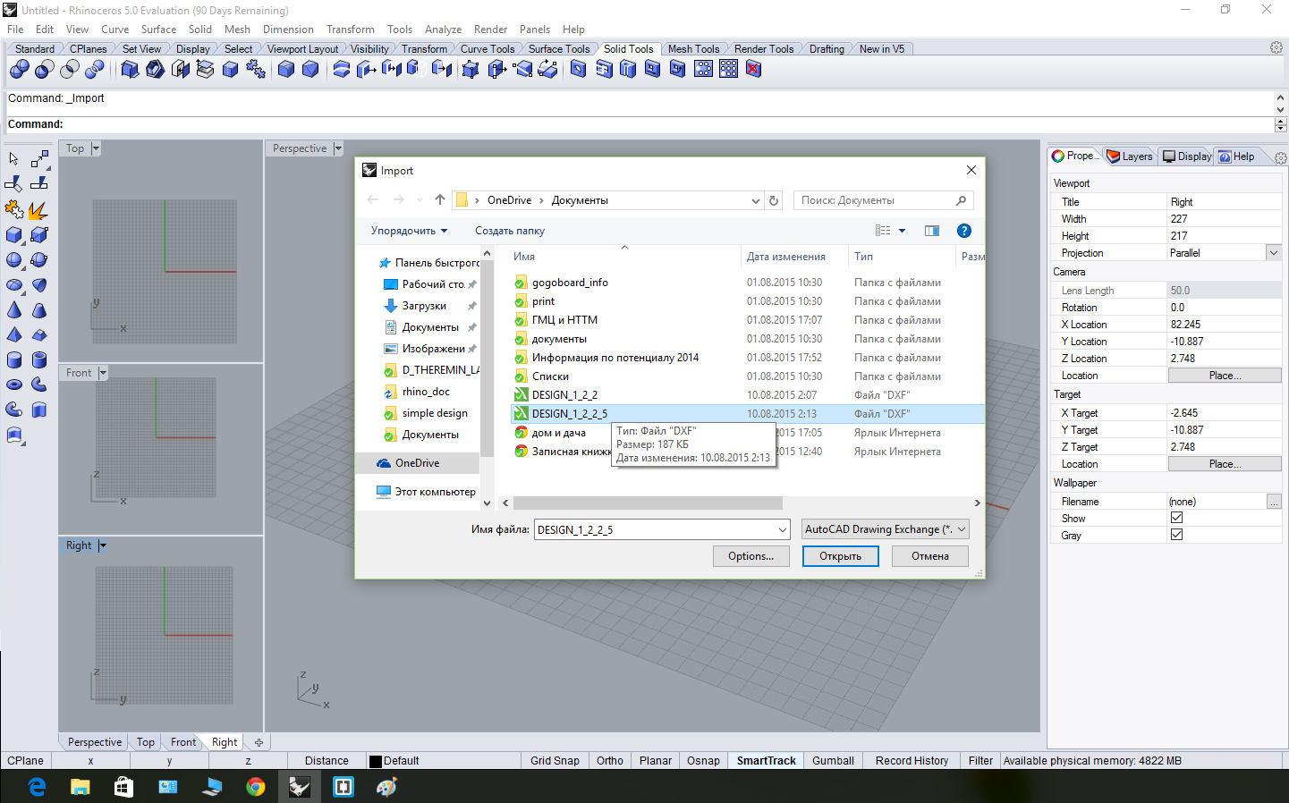
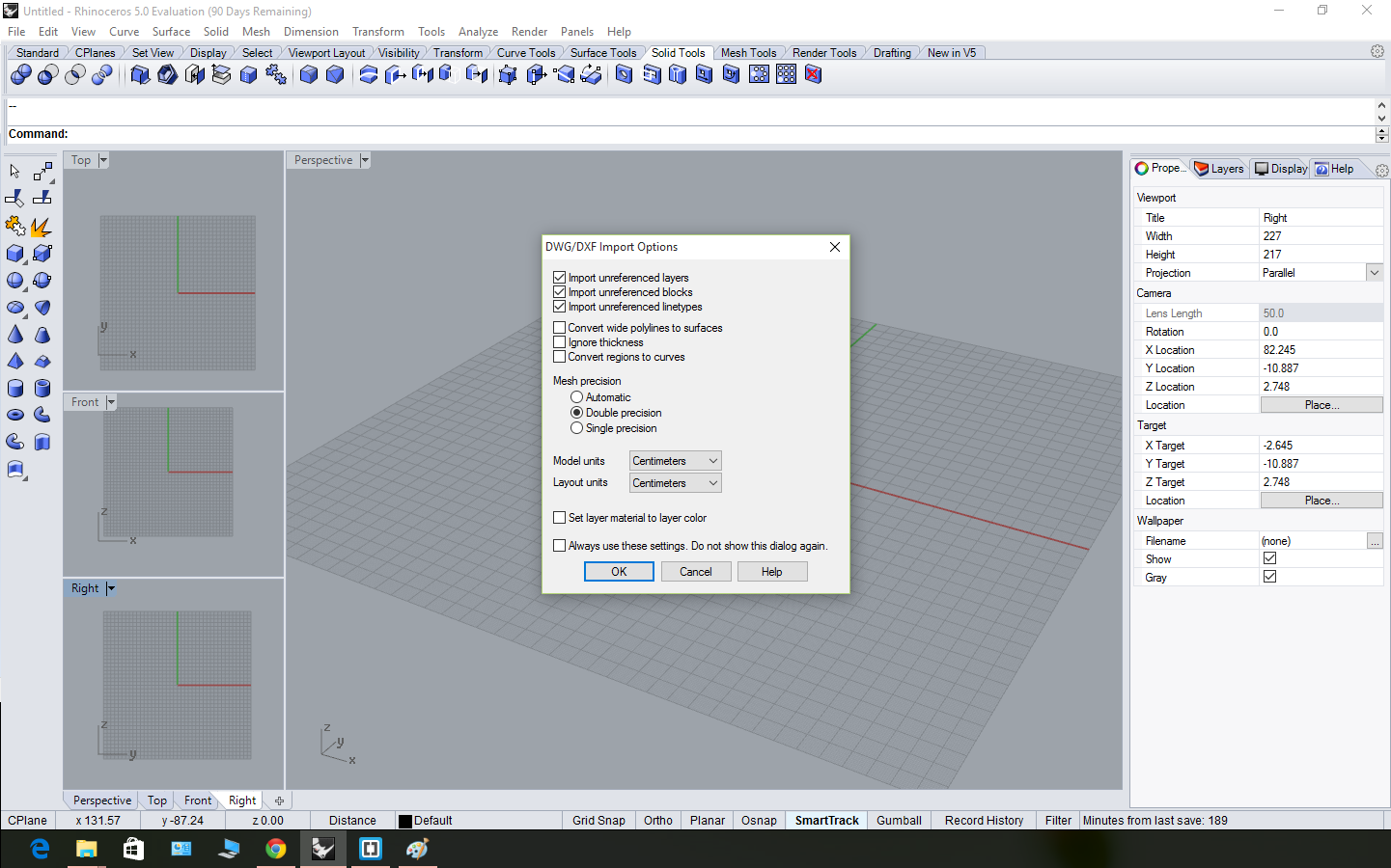
Thus, the very first thing was finding out how to do that. Rhino didn't want to import the *.svg, so I tried the *.dxf and it worked! The only probem I faced here was matching the scale (I had to choose centimeters to have the real-sized details, which semms a little odd to me). Anyway, we have the outlines imported (they are called "curves" here)! Here are some process screenshots:
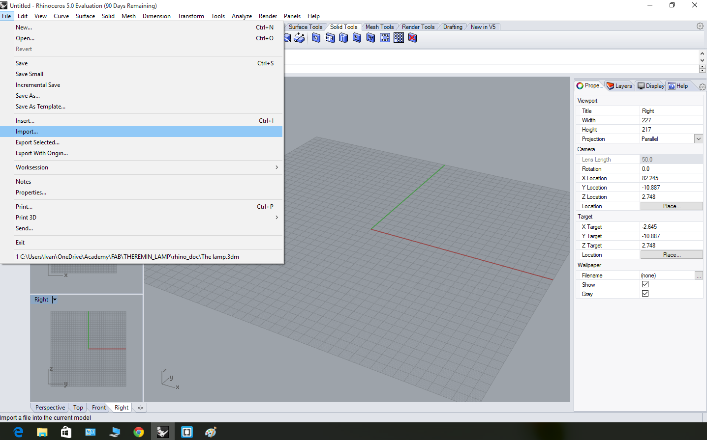
Import in File menu:
|
Choose a file:
|
Import settings:
|
Import is done:
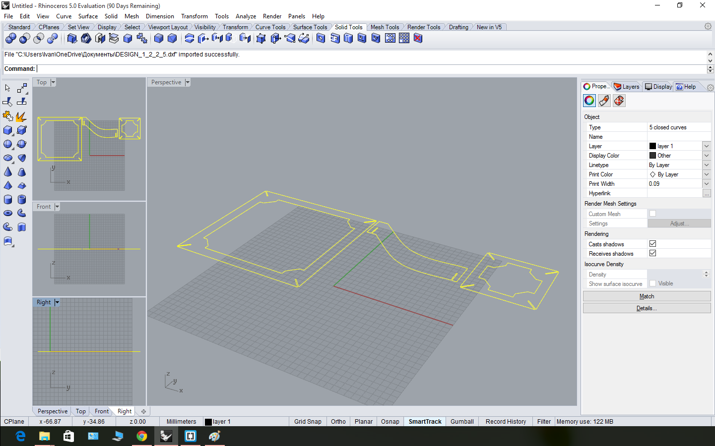
|
That was a little bit tricky at the start! I got used to the fact that any shape can be extruded into a solid shape untill I tried rhino! Basicaly, when you try to extrude from a curve, you have a only a surface, not a solid! It seems quite logical now, but it took me some time to understang the sequence:
curve -> surface -> body,
because usially we pass the second step, because it is concidered that a closed curve on a surface is a surface itself!
I have spent about 15 minutes trying to make solid boolean operations with thise things and trying to understand why the objects "do no intersect":
Extruding the curve
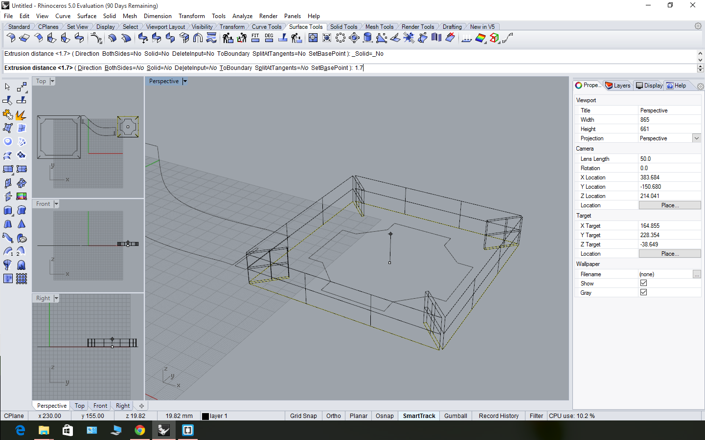
|
It's 1,7 mm high (like the cardboard thickness).
|
And I can't make boolean substraction!
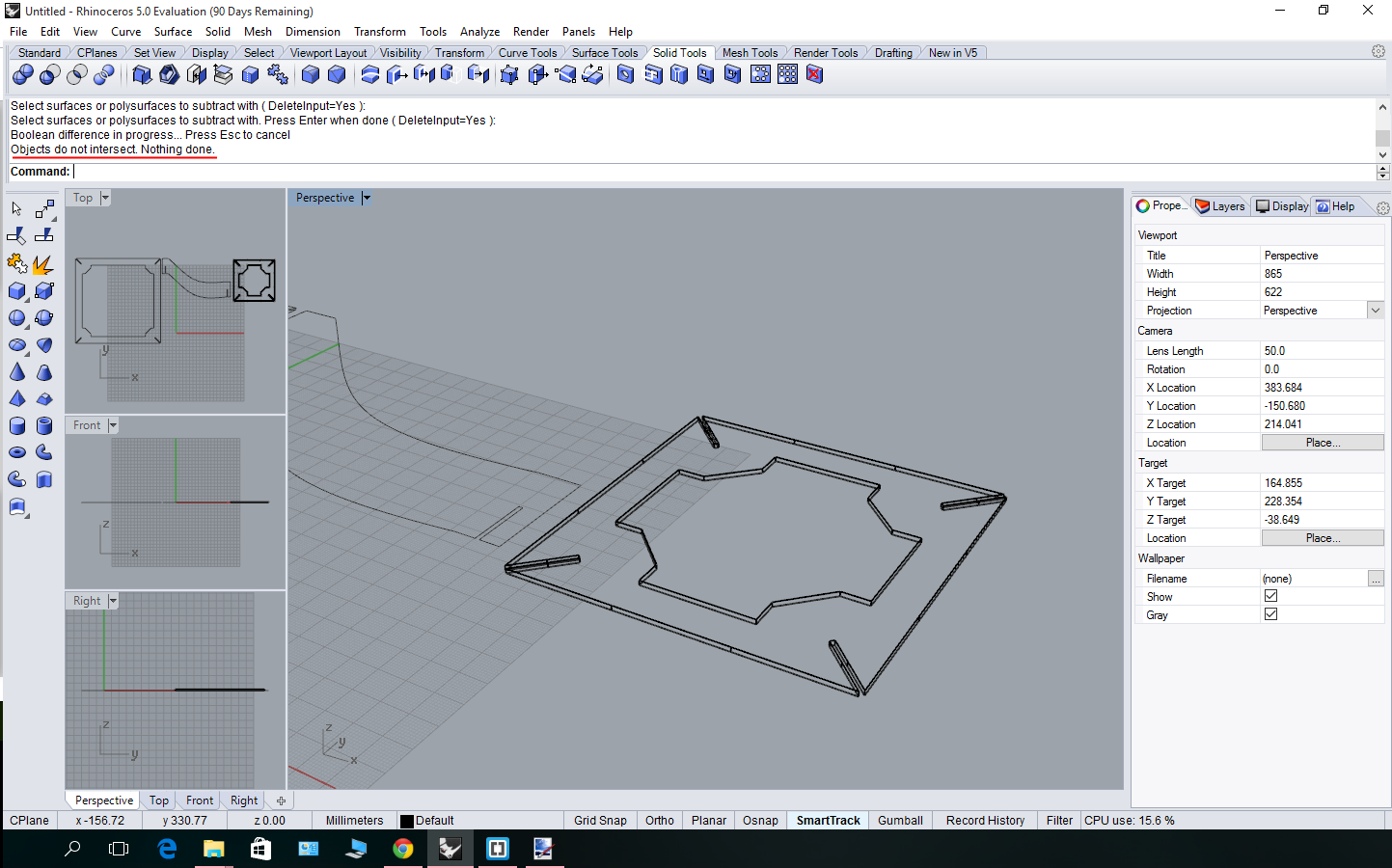
|
The solution was easy: I had to make a surface from a planar curve and then (operation "surface from the planar curves" in "surface tools" menu, only after this, I could "surface extrude"! Here are the screenshots:
That's the curve yet
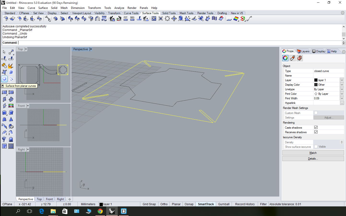
|
Now that's the sutface!
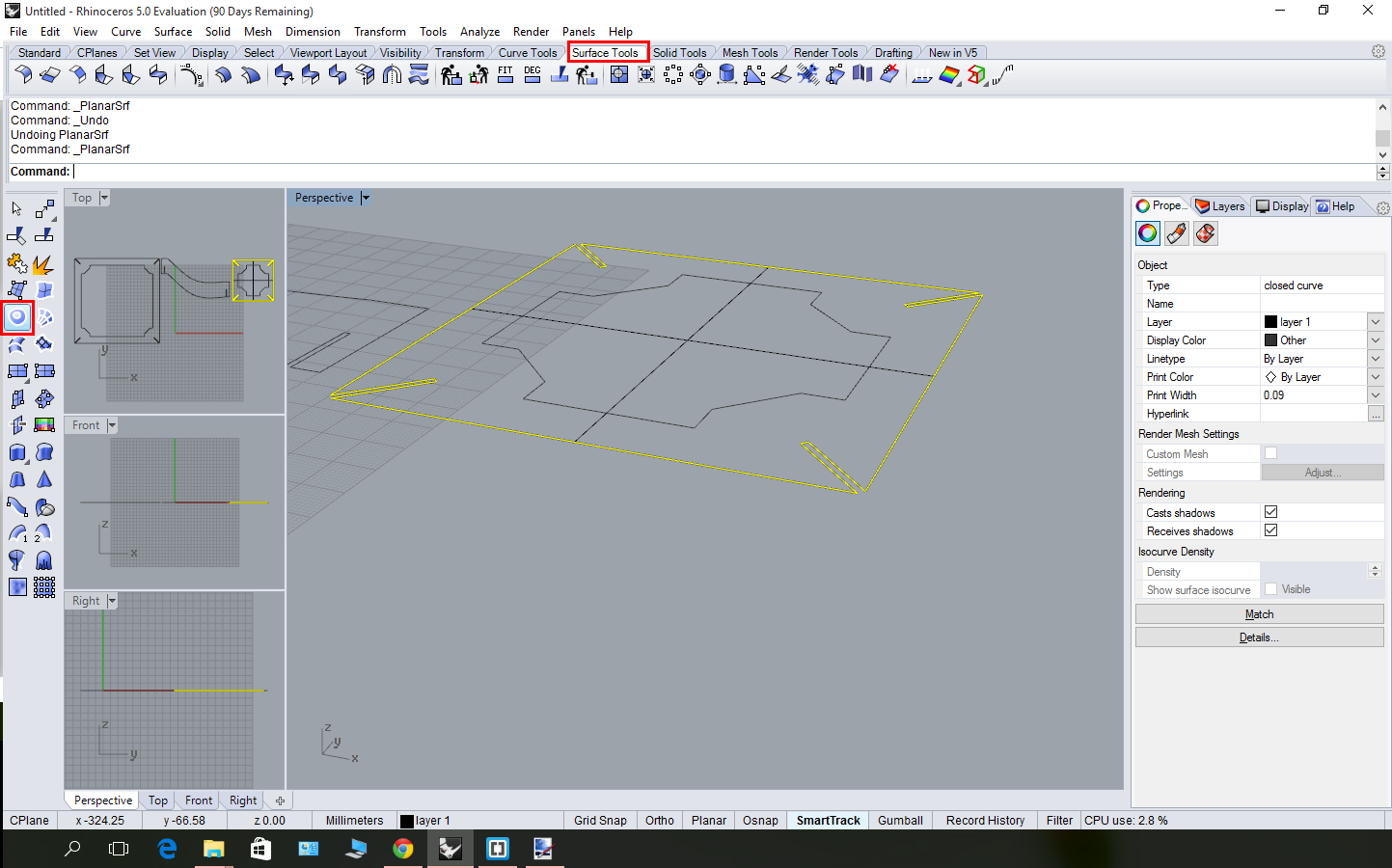
|
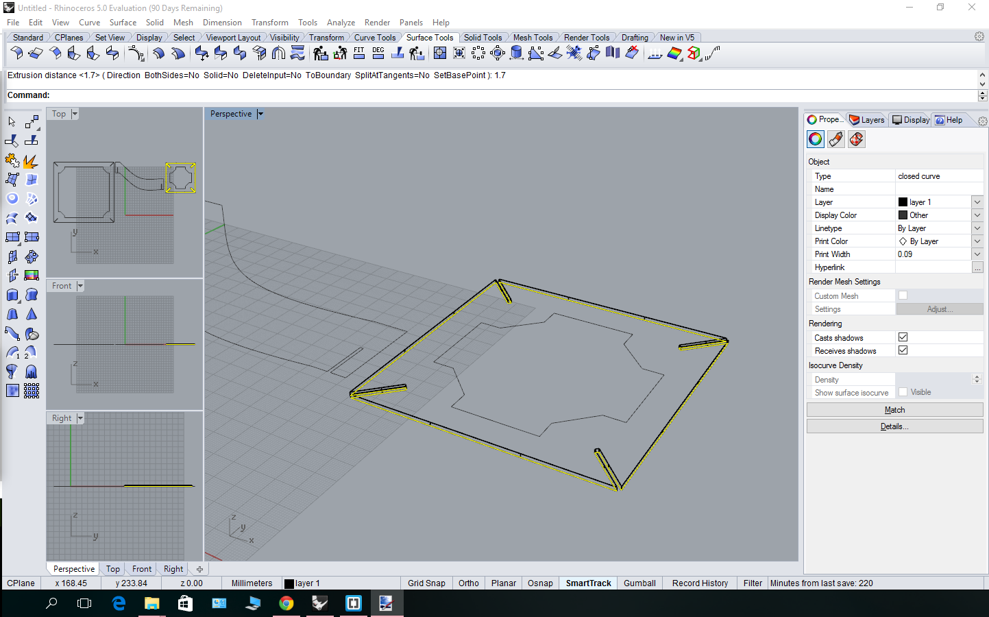
Now surface extrude for 1,7 mm (cardboard width).

|
Now we can make solid bodies from all the curves:
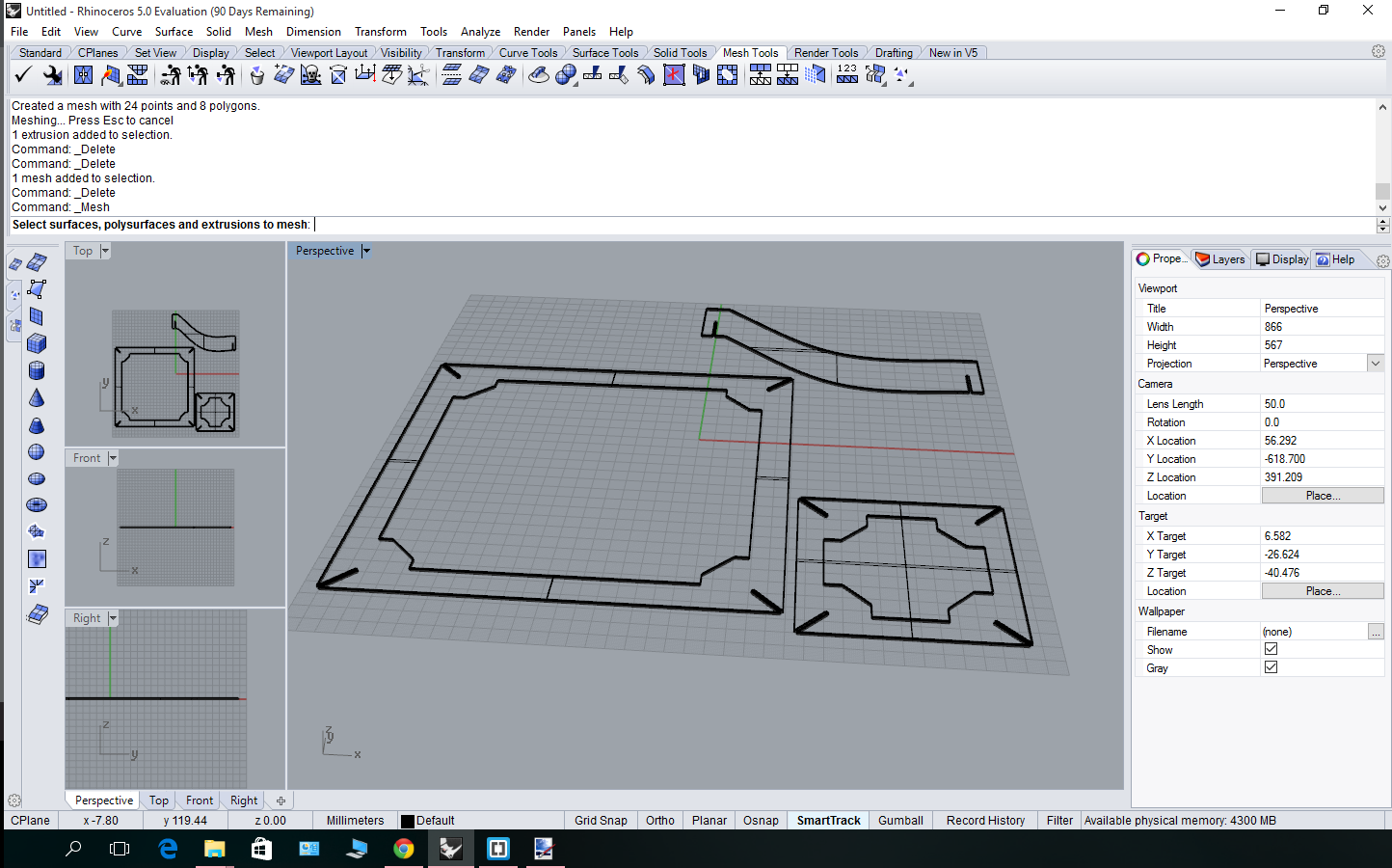
The next spet was to combine the details. That's what I had when I assembled everything:
Seems a little odd, doesn't it?...
|
That's the problem! The upper plate is to small!
|
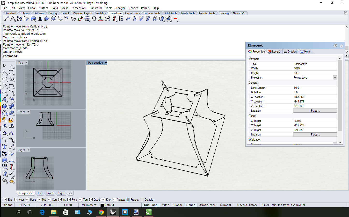
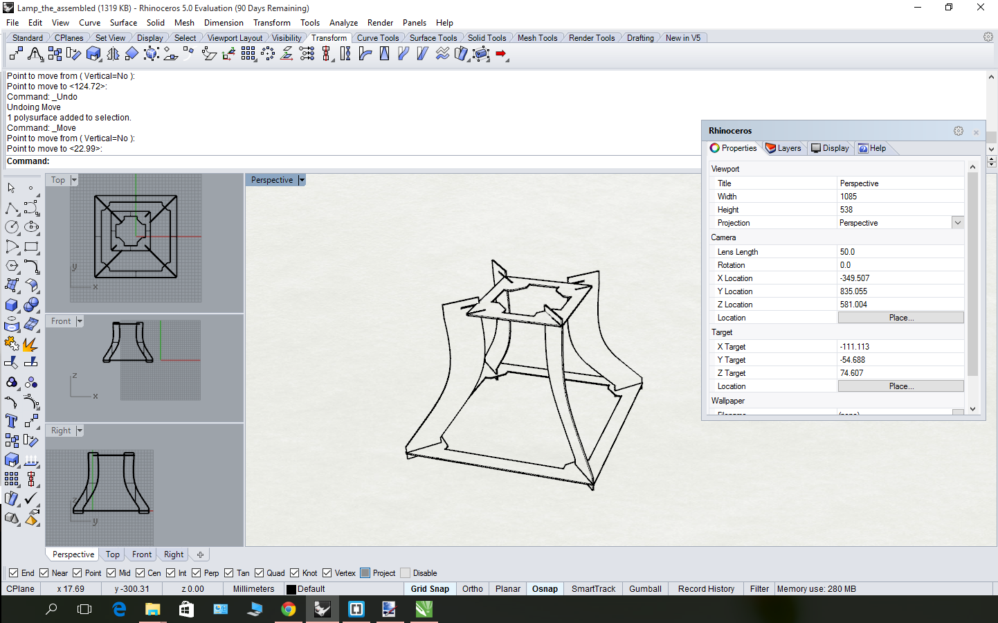
That's how it looks like after I madde the upper plate bigger (that is the final result):
Now I can tell for sure that this lamp blueprints are good enough to assemble the lamp from them! Here is the CorelDraw file with the design, dxf-export from corel-draw (for you to be able to copy the lamp) and 3d-model in rhino!