W19 - APPLICATIONS AND IMPLICATIONS
GOAL
This week's goal is to plan and document the final project.The main goal at the beginning of the course was to produce an open source quad-copter able to fly and collect data about the environment. There are many software able to rebuilt the context using pictures taken by the drone and generate information based on the data that it collects. As the end of the academy approach I lowered a bit my goal and decided first to make the drone fly!
Since I’m working in a group, as suggested by Neil, we decided to add a mechanical part and another elettronical part to the drone. That’s how the idea of the gimbal came up.
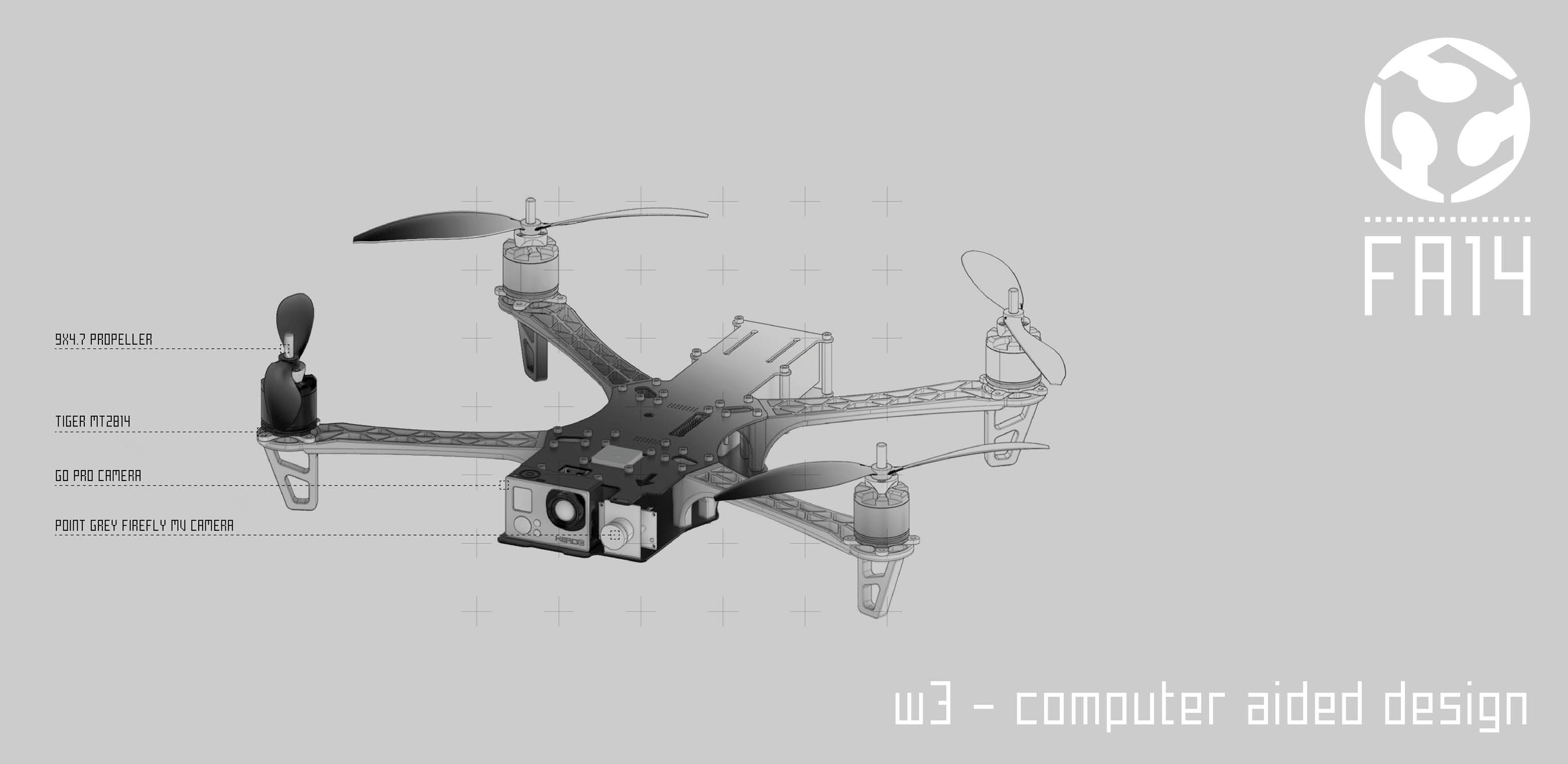
On this document I’m going to focus on this last one as the informations relative to the main drone are documented on the website of my partner in crime Chirag Rangholia.
WHAT WILL IT DO?
A gimbal is a pivoted support that allows the rotation of an object about a single axis.A set of three gimbals, one mounted on the other with orthogonal pivot axes, may be used to allow an object mounted on the innermost gimbal to remain independent of the rotation of its support (e.g. vertical in the first animation). For example, on a ship, the gyroscopes, shipboard compasses, stoves, and even drink holders typically use gimbals to keep them upright with respect to the horizon despite the ship's pitching and rolling. Our gimbal has a GoPro camera mounted on it.
The gimbal gives to the camera a perfectly leveled video footage, no matter how you move the drone.
The servo motors of the gimbal will control the pitch and roll rotation of the camera.
There is no motor for yaw. More informations regarding those topics are available here.
WHAT HAS DONE BEFOREHAND?
A lot of gimbal have been made up today.
I found a very interesting website that share all the open source gimbal online.
Because there is a lot of documentation online let’s start from an interesting topic: servo motor or brushless motors?Servo Based Gimbals
• Cheaper than brushless gimbal - servos can cost more than certain brushless gimbal motors, but you dont usualy need a special controller/battery just for the gimbal
• Much lighter than equavalent brushless gimbal - servos are much lighter compared to a heavy brushless motor) • Much easier to setup and use - most flight controllers support servo base gimbals directly. Brushless gimbals usualy require a separate control board (FY-G3 gimbal22 has one integrated with each motor).
Brushless Gimbals
• Much better stabilization - the speed and smoothness of brushless gimbals is unquestionably better than servo based gimbals. Some complex servo based gimbals that use gears and timing belts achieve good stabilisation, but they are still slower than direct drive brushless gimbals.
• Some ready to use brushless gimbals work right out of the box, so you dont need to spend any time balancing and setting it up which can sometimes take abit of time (see our guide here)
HOW MUCH WILL IT COST?
One roll of PLA cost 60 euro since we need only a 1/6 the actual price for material for gimball is 10 euro.From the other end we need two servo motors. It is possible to buy all of them online but I went to a shop full of material here in Bcn (RcTecnic). Price for each servo 7 euro.
The total amount for the mechanical part is than: 24 euro.
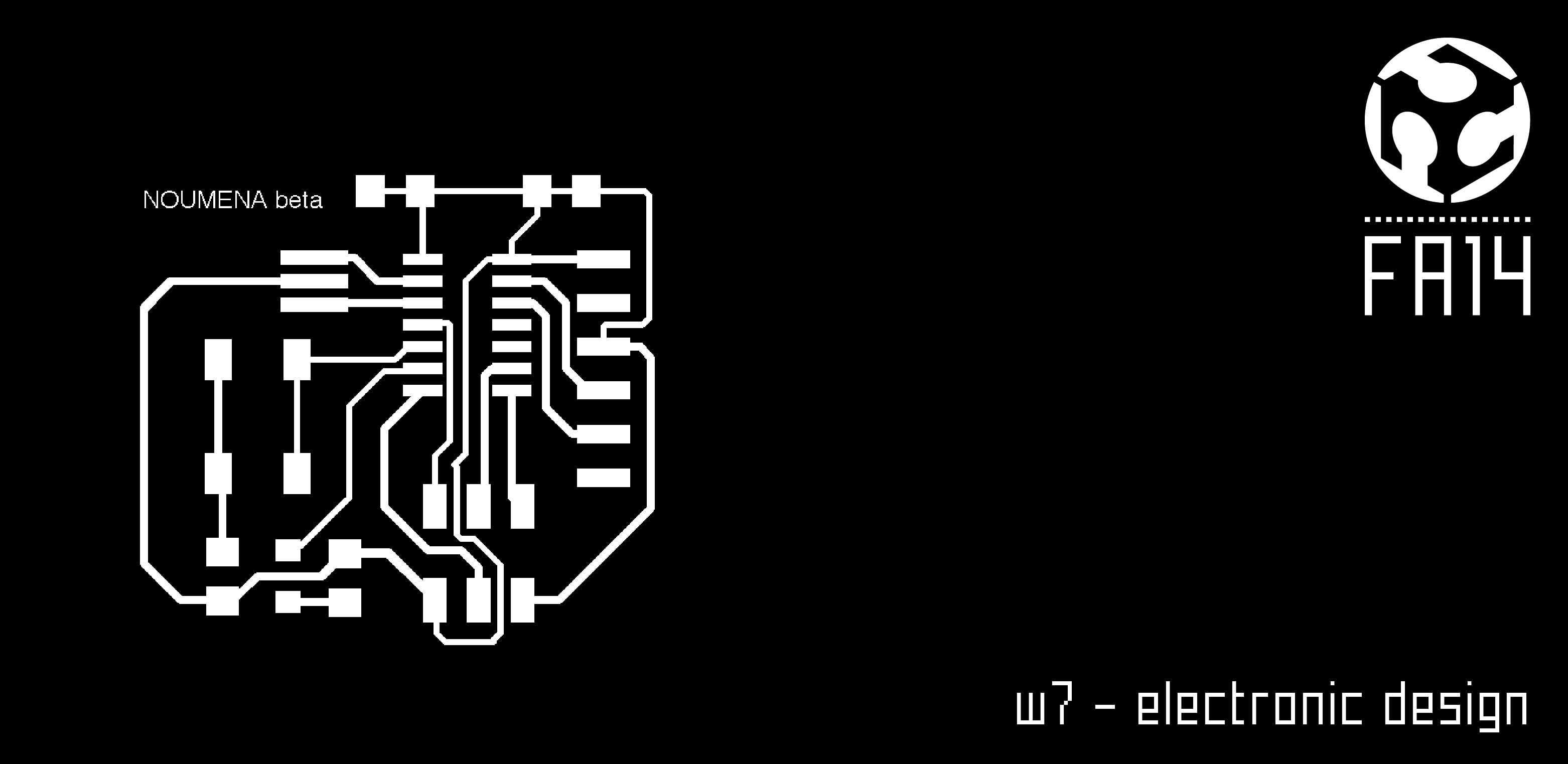
The components used for the board are
• 6Jumpers M031X03_NO_SILK (M03) : 40 cents each
• 1 AB9V : 10 cents
• 5 JST_2PIN-THM (JST_2PIN) : 1 cent each
• ATTINY45SI (ATTINY45): 1.35 euro each
• 1 pinheader connector : 2 euro
• 1 voltage regulator LM317DCYR: 2,5 euro
WHAT PARTS AND SYSTEMS WILL BE MADE AND WHAT PROCESS WILL BE USED?
I’m planning to 3d print the entire mechanical part of the gimbal. Since all those components are quite smalls I can 3d print an entire gimball in 2 hours.
For the electronic part I’m going to mill a breakout board using the Roland Moldela as learned in previous assignments.
WHAT TASKS NEED TO BE COMPLETED?
I already start testing the single components but the perfect combination between those parts, the drone, the camara and the servo motors has yet to be improved.More than that I need to implement the code into the main one of Multiwii code that is programming the drone.
The main task would be found the pin connected to the servo and than calibrate the rotation of the camera.
WHAT QUESTIONS NEED TO BE ANSWERED?
Mainly it’s about finding the right balance between rotation in the code and physical one. Is it possible to add also another servo for the yaw?
I want to consider also that option.
WHAT IS THE SCHEDULE?
By this week it would be good to fix the mechanical part.The servo motor we are using can support 2 kg so we are still considering if use gears or connect directly the servo to the main axis of rotation. The general advise is to avoid such a solution in order not to breake the servo in case of something going on on the main axis.
Once the mechanical system is set up I’ll move to embed the code into the drone’s one.
Than find the right pin outs on the board, setup the rotation angle and cross my fingers!
HOW WILL IT BE EVALUATED?
The gimbal system will be evaluated based on the ability it will show in rotating (pitch and roll) according to the drone movements.We can make it!
Weekly Assignments