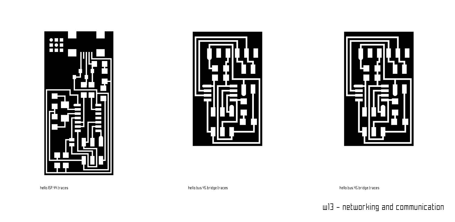
W13 - NETWORKING AND COMMUNICATION

W13 - REFERENCES
link: hello.bus.45.bridge
link: hello.bus.45.bridge tutorial
W13 - DOWNLOADS
design files
In this assignment I designed a network between three boards. For the assignment I used my ISP done in previous assignments and two new boards hello.bus.45.bridge.cad.
To program those boards is necessary to download the files in the archieve and run them in Ubuntu (or if you have a Mac you can run it there of course). Not my case. To do that I used and run the programming using the sudo module.
My target was to switch on a led in both boards used as bridge.
There is an issue with Neil's C old code so it's important to correct string n.220. The issue is to put the word "const" at the beginning of the line.
The target as said is to do at least 2 nodes.
In ubuntu I changed the raw 41 selecting the right node id "0" for the bridge and "1" and "2" for the two nodes.
Here I report the steps that I follow usign this link as a reference:
Modifing the C Code
1) For each node in your network, you will need to modify the modify the "hello.bus.45.c" code. The "bridge" board with the FTDI header is also technically a "node".
2) Each node needs to have a different node ID number (0, 1, 2, 3, etc)
3 )In the c code, you need to change the line:
#define node_id '0'
Save the file. Conncet the bridge board to your computer with the FTDI header and using your FabISP, flash the bridge board as node 0.
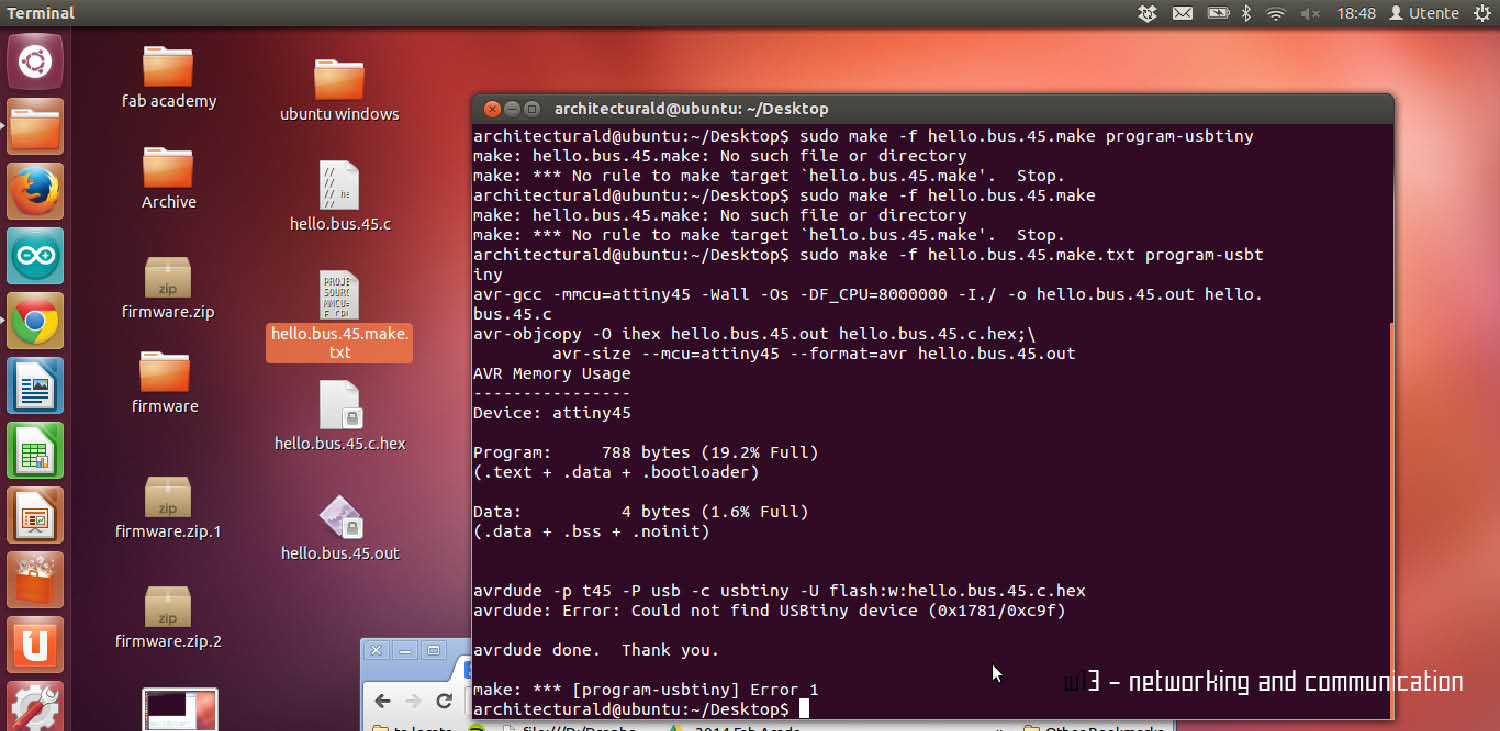
sudo make -f hello.bus.45.make program-usbtiny
Next, modify the C code again and change the node id to 1
Then save the file.
In the image below you can see I had some issues programming the second node. However once I fixed it the system worked well.
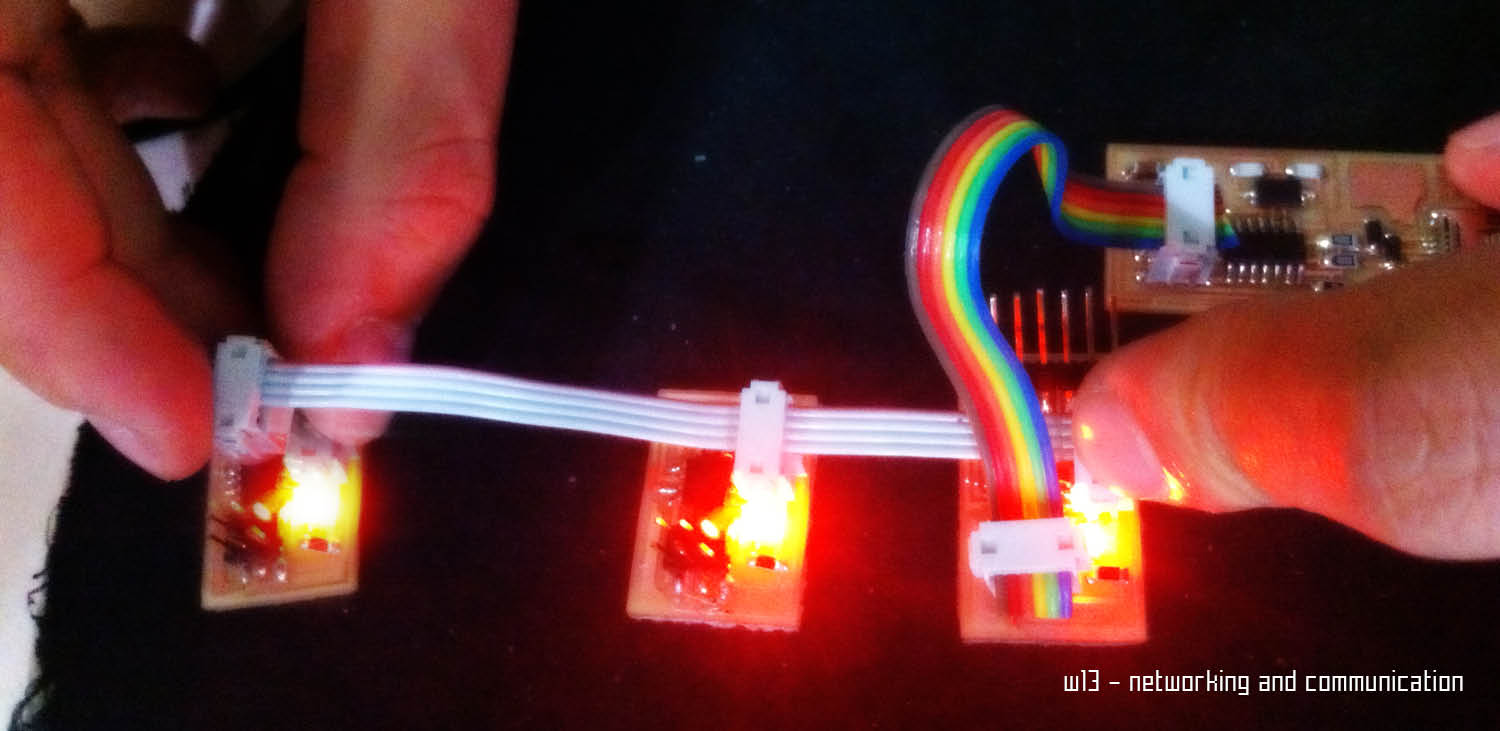
Here is the system in action! After programming the boards, a part a little instability in the headers connections, all the three leds blinked and here you can see the bridge and the two nodes working togheter.
Weekly Assignments