W10 - INPUT DEVICES
W10 - REFERENCES
link: thermistor tutorial
link: shopbot
W10 - DOWNLOADS
design files
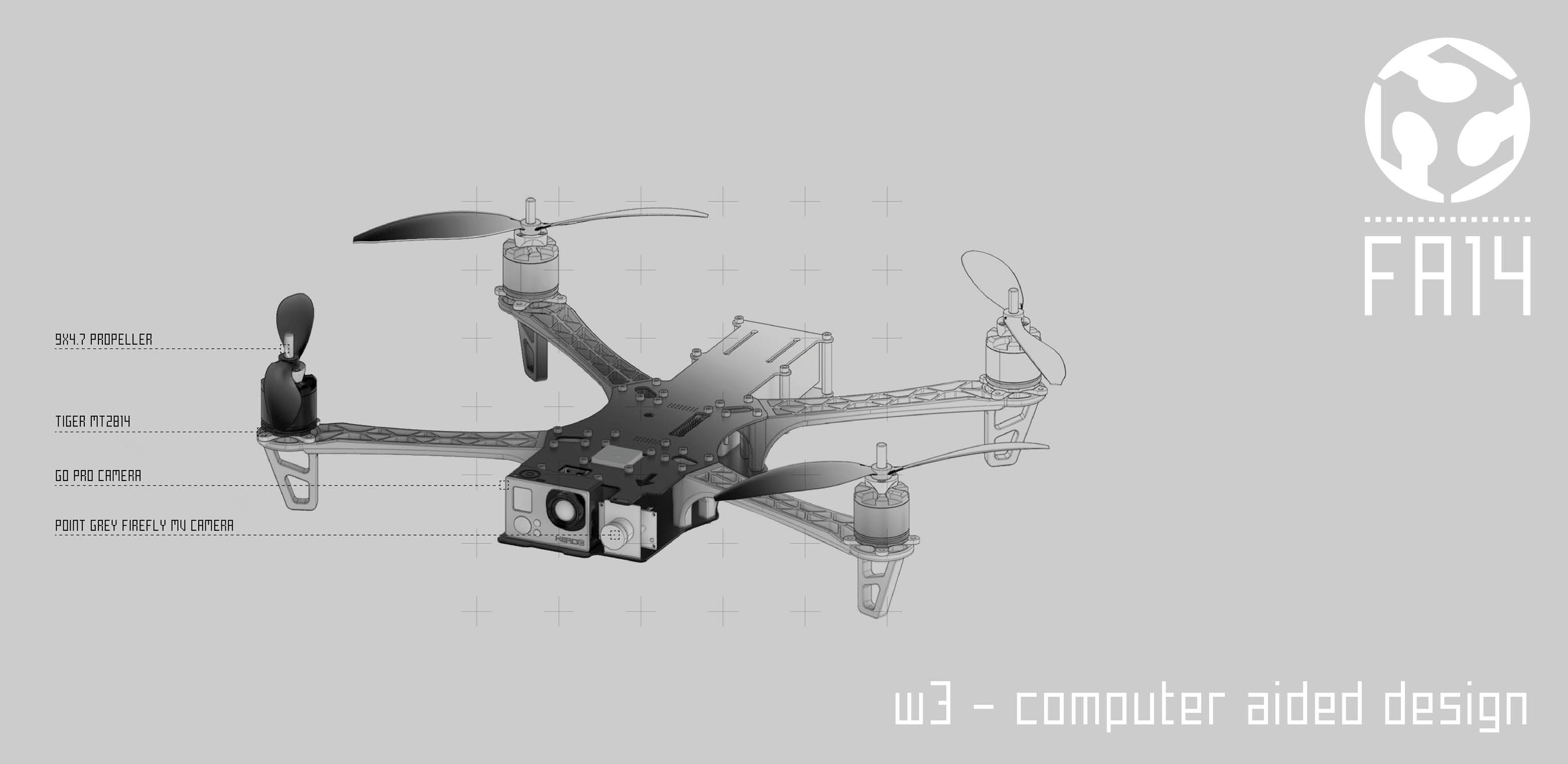
The assignment of this week is focus on receiving an input from one of the components on our board or in a shieldboard.
I decided to design a specific shield for temperature as reported in the files of the archieve.
To receive and read this input I did an hello.duino board adding several pins to the one avaiable online in the directory of the academy.
In this way I'm using the heighest number of pins and the board is more efficient.
I used a Mac and I could run the bootloader for the board. Since I'm using a Windows I wanted to be able to run bootloaders also on my computer.
And here the problems started.
I tried to run it many times but without any success...until I burned the board!
So I did it again another board. This time since the ATmega32 was over in the fablab I put a ATmega16. I didn't change anything else since it was supposed to work with the same resonator of 20mhz.
The bad news was behind the corner. The library of ATmega works with resonator of 8 or 16. With the tutors we tried to run the bootloader and creating a library for the 20mhz resonator and the ATmega 32. Again after several hours the result was another burned board.
For this reason I couldn't achieve to do all the process with my hello.duino but I moved on.
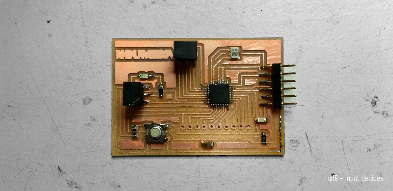
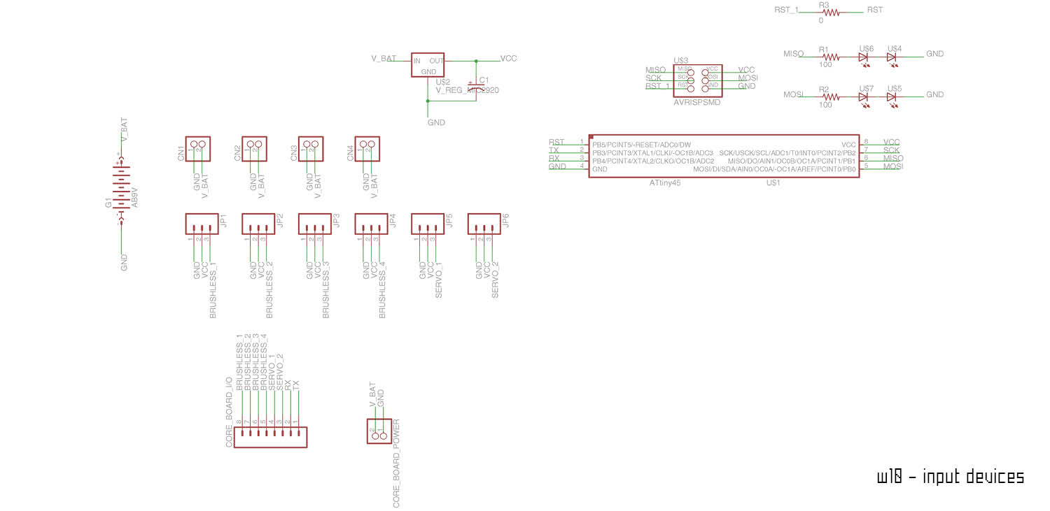
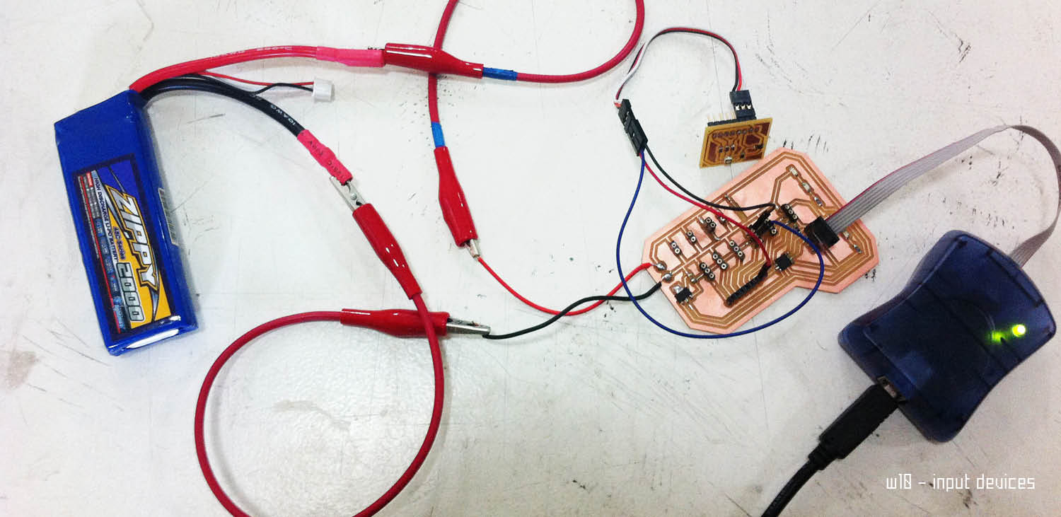
The board to record the temperature was anyways ready. It's made of very few components. The shield needs a power supply (VCC) and a GND directly connected to the main board. It also have a PIN OUT that again connect the inputs of the Temperature component to the header connected to the microcontroller of the board.
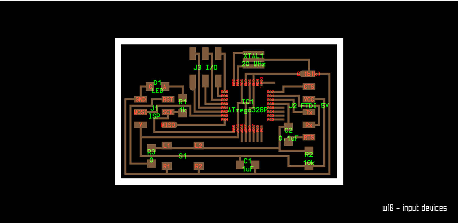


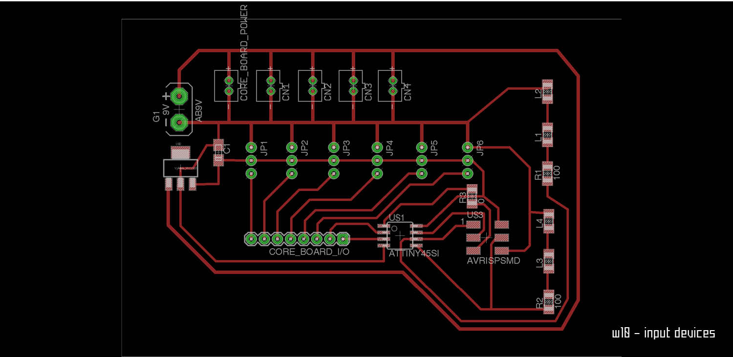
step 05 - board
The second try came weeks later after the board for the final project was already done.
This board have an ATtiny45 with an internal resonator of 8mhz. The board have several pin outs and headers. The idea is to use it to read with the serial all the datas coming from the shield board that is still working.
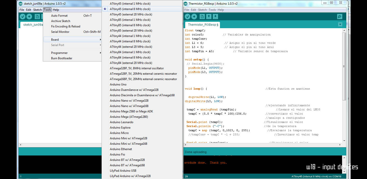
The logic is not complex. I run the bootloader and this time it works!
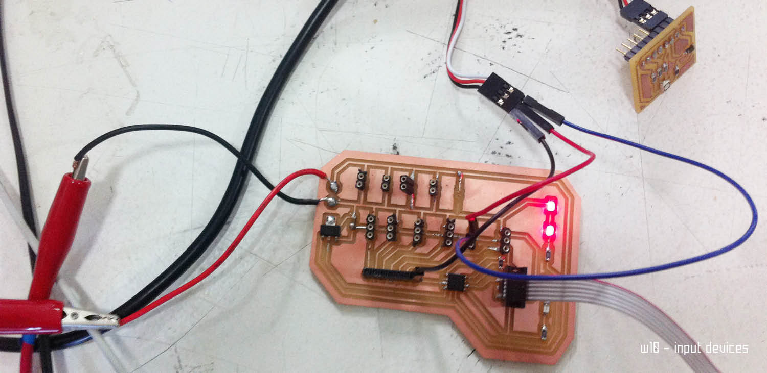
I can move to the code. There are several examples online of arduino and thermal sensors. I follow one of them. This time I have to adjust it to my board of course. The logic is the same. Connect VCC GND and PIN to the one of the main board. OF course I have to check the datasheet of the ATtiny45 and make all the pinout correspond.
It's working! I can read values and have as a resultant of the input my leds turning ON!
Weekly Assignments