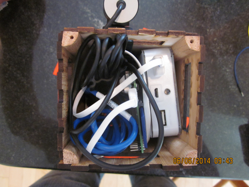
The feeder consists of a 3D printed main feeder for
containing feeding liquid. A Ping Ultrasonic sensor detects bird
arrival at the feeder and sends serial data to a Raspberry Pi
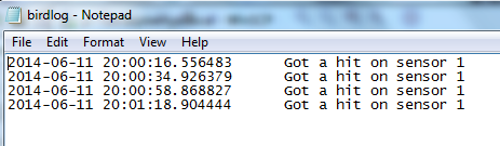
board. The Pi board uses Python code to record the bird visit in a log file with a time
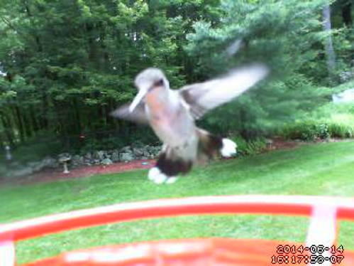
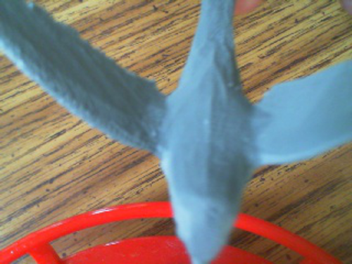
stamp. In addition, the Python code triggers a webcam to take a
photo of the bird.
Design Goals
Basic Functionality (feeds hummingbirds).
Proximity sensors to record visits.
Time stamps of visits to capture behavior
patterns.
This was a very successful project and all design
goals were achieved. The feeder works well in lab environment. At
time of writing, feeder had just been located outside and so far
hummingbirds are proving elusive using Ping Sensor. A switch to
using the webcam with motion detect software was more successful.
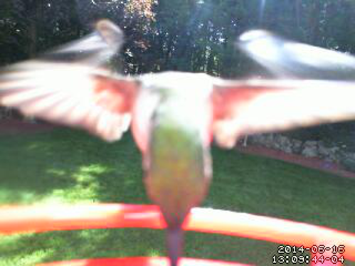
Below are some snapshots that show how the Ping Sensor system
works:
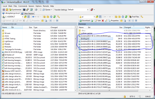
WinSCP screen capture (local file on left, Pi
files on right showing 4 successive image captures)
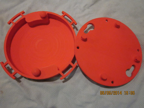
The feeder design consists of two components, a
feeder base and a feeder cover. Both were designed in Solidworks.
Both parts were printed on a Stratasys Prodigy Plus 3D Printer
using ABS Plastic. More information on the printing process is
contained in the weekly
update for 3D scanning and printing.
Design Features include a locking mechanism for top cover, hanging
hooks and bird perches.
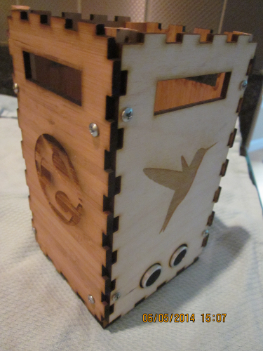
Design was completed in Inkscape utilizing
the Tabbed Box Maker extension.The tab dimensions were not
correct but the effect produced an interesting design that was
kept in the final product.
Box pieces were cut by Laser Cutter and
decorative designs were made by rastering on Laser Cutter.
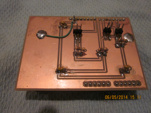
The sensor board was designed in Eagle. The
Arduino base outline was imported from Adafruit library and the
design was developed from there. This board plugs directly into
an Arduino Uno board. The caps and resistors were through hole
parts soldered to surface mount pads (due to availability) which
is a relatively easy process. The large copper pad around the
outside was turned into a ground plane by soldering a wire to
the ground pin as shown in the photo. The board consists
of 3 channels intended for 3 separate Capsense signals.
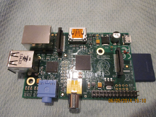
The Raspberry Pi board is a computer board based on
Broadcom ship technology. For a more detailed background see the Wikipedia
summary.
The setup of the Raspberry Pi board is time consuming but is well
documented. This was summarized in my Networking and
Communications weekly summary.
The Raspberry Pi board has a lot of functionality
and this application utilizes only a limited amount of that
functionality. The primary need for the Pi in this project was to
drive the camera.
The process of setting up the connections to the
Raspberry Pi is time consuming (for list of inputs see Networking and
Communication Weekly Update). An alternative is to work on
the Pi remotely from any location and this can be done using VNC
(Virtual Network Computing). This requires a VNC download to the
Pi and also to the PC to be used.
An additional challenge is to transfer files from
the Pi. One possibility is to use webmail but this proved to be
too slow. Another possibility is to add an email service on to the
Pi. My solution was to use WinSCP which provides an elegant window
to drag and drop files from Pi to laptop.
Controller Board to Raspberry Pi
Communication from the Pi board to the Controller
(Arduino) board is via Serial USB.
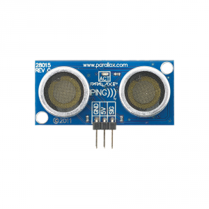
The Ping Ultrasonic sensor measures distance by
triggering an ultrasonic burst and then listening for the return
pulse. It measures the time required for the return pulse.
Software on the controller board can then be used to convert this
time delay into actual distance. It is then easy to create a
threshold to trigger some action when an object comes within a
specific distance from the sensor. The sensor used in this project
is manufactured by Parallex.
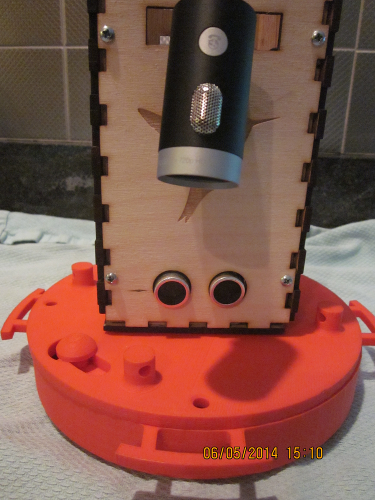
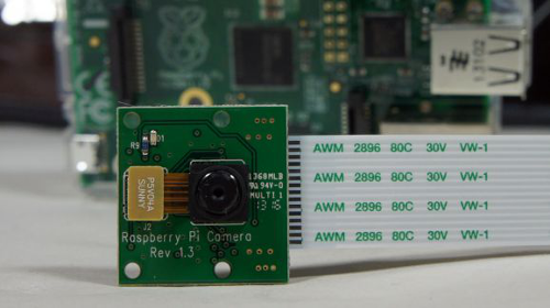
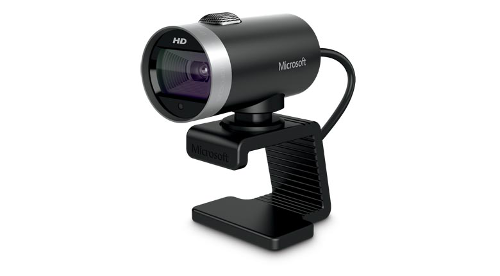
Pi camera (left) and Microsoft Webcam (right) - not to scale
The original intent was to use the Raspberry Pi
camera module. However, two devices in a row failed (suspected
static damage) and so the design was modified to incorporate a
Micorsoft Webcam which was available unused in my home office. The
webcam has a USB cable which can be plugged directly into the Pi
board.
SimpleCV was downloaded to the Raspberry Pi to interface with the
Webcam and Python commands were used to control the camera.
The webcam and Ping sensor
design worked well in the lab, however the birds did not
appear to like the setup. Possible reasons are the visual
appearance of the sensors (look like big black eyes) or
perhaps the birds are repelled by the ultrasound pings. In any
case, an excellent workaround is to use motion detect software
on the Pi. This eliminates the need for a sensor and a
controller (Arduino) board. There are a number of good
tutorials available including this
one. This motion detect software
enabled the videos and stills listed above.
Capacitive Sense
The original design intent was to use capacitive
sensing to detect the arrival of a bird at the feeder. The
capacitive sensing technique is well explained well in the
Arduino Capsense library. At a high level, the method is
based on measuring the time difference between a state change in a
Send pin and a Receive pin. This time will depend on the
capacitance used in the system plus any capacitance provided by a
human touch or proximity.
Issues Encountered with Capacitive Sensing
This method proved not to be very reliable,
robust or transferable and was abandoned as a practical method
for bird detection.
Grounding is a major issue and values/behavior
vary widely depending on the setup (what works on a breadboard
may not work on a soldered board).
A number of iterations were tested with
different grounding schemes but none provided reliable
results.
Related to grounding, values and behavior vary
widely depending on cable connections (e.g. when USB cable is
moved from laptop/controller board to Pi/controller board).
It appeared that in most configurations
multiple activations were required to reach baseline levels
(this contributed to significant false positives).
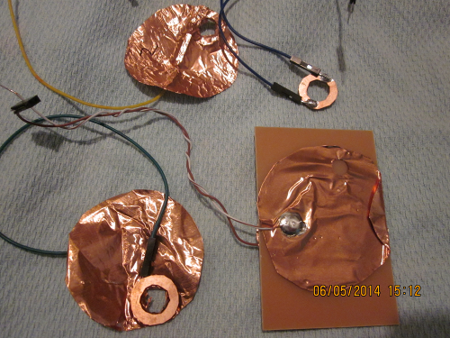
A number of pad designs were tested but none
seemed to provide improved results. These included copper
foils and double sided PCB's milled in donut shapes on the
Modela milling machine.
Sample of pad designs
Capsense Code
The code used in this project was based on the Capsense libarary but
also added a calibaration routine to determine a baseline threshold.
#include <CapacitiveSensor.h> /* * CapitiveSense Library Demo Sketch * Paul Badger 2008 * Uses a high value resistor e.g. 10M between send pin and
receive pin * Resistor effects sensitivity, experiment with values, 50K -
50M. Larger resistor values yield larger sensor values. * Receive pin is the sensor pin - try different amounts of
foil/metal on this pin */ int sensor_1_baseline = 0; int sensor_2_baseline = 0; int sensor_3_baseline = 0; CapacitiveSensor cs_4_2 =
CapacitiveSensor(4,2);
// 10M resistor between pins 4 & 2, pin 2 is sensor pin, add a
wire and or foil if desired CapacitiveSensor cs_4_6 =
CapacitiveSensor(4,6);
// 10M resistor between pins 4 & 6, pin 6 is sensor pin, add a
wire and or foil CapacitiveSensor cs_4_8 =
CapacitiveSensor(4,8);
// 10M resistor between pins 4 & 8, pin 8 is sensor pin, add a
wire and or foil void
setup()
{
cs_4_2.set_CS_AutocaL_Millis(0xFFFFFFFF);
// turn off autocalibrate on channel 1 - just as an example
cs_4_6.set_CS_AutocaL_Millis(0xFFFFFFFF);
// turn off autocalibrate on channel 1 - just as an example
cs_4_8.set_CS_AutocaL_Millis(0xFFFFFFFF);
// turn off autocalibrate on channel 1 - just as an example Serial.begin(9600); calibrate(); } void
loop()
{ long start = millis(); long total1 =
cs_4_2.capacitiveSensor(30); long total2 =
cs_4_6.capacitiveSensor(30); long total3 =
cs_4_8.capacitiveSensor(30); /* Serial.print(millis() -
start); // check on
performance in milliseconds
Serial.print("\t");
// tab character for debug windown spacing
Serial.println(total1);
// print sensor output 1 Serial.print("\t");
Serial.println(total2);
// print sensor output 2 Serial.print("\t");
Serial.println(total3);
// print sensor output 3 */
delay(10);
// arbitrary delay to limit data to serial port if(total1 < sensor_1_baseline) { Serial.print("Got
a hit on sensor 1. Value = ");
Serial.println(total1); } if (total2 < 197000) { //trial
and error value based on serial display readings Serial.print("Got
a hit on sensor 2. Value = ");
Serial.println(total2); } if (total3 < 200000) {//trial
and error value based on serial display readings Serial.print("Got
a hit on sensor 3. Value = ");
Serial.println(total3); } } void calibrate() { int sensor_1_total=0; int sensor_2_total=0; int sensor_3_total=0; for (int i = 1; i <= 10; i++){ sensor_1_total = sensor_1_total +
cs_4_2.capacitiveSensor(30); sensor_2_total = sensor_2_total +
cs_4_6.capacitiveSensor(30); sensor_3_total = sensor_3_total +
cs_4_8.capacitiveSensor(30); } sensor_1_baseline = int(sensor_1_total / 10); sensor_2_baseline = int(sensor_2_total / 10); sensor_3_baseline = int(sensor_3_total / 10); Serial.print("Sensor 1 baseline = "); Serial.println(sensor_1_baseline); Serial.print("Sensor 2 baseline = "); Serial.println(sensor_2_baseline); Serial.print("Sensor 3 baseline = "); Serial.println(sensor_3_baseline); }
This code is measuring the time for the Ping
cycle and converting that to distance based on the component
specification. Experimentation found the results to be extremely
accurate. A threshold of 3 inches was set to execute a data send
to the serial port (this data is then read and used by the
Python code on the Raspberry Pi).
const int pingPin = 12; // Signal Pin on the Ultrasonic Range
Sensor void setup() { Serial.begin(9600); // initialize serial communication: } long duration, inches, cm, inMean, cmMean; // Set the
variables duration, inches, cm, inMean and cmMean to long long in[] = {0,0,0,0,0}; // Set variable in for the inches
filter to long long cen[] = {0,0,0,0,0}; // Set variable cen for the
centimeter filter to long int arrayIndex = 0; // Set variable arrayIndex to integer in
inches and cm filter void loop() { // The PING))) is triggered by a HIGH pulse of 2 or more
microseconds. // Give a short LOW pulse beforehand to ensure a clean HIGH
pulse: pinMode(pingPin, OUTPUT); // Define pingPin as an output.
//// digitalWrite(pingPin, LOW); // Write LOW. //// delayMicroseconds(2); // Wait 2 microseconds. //// digitalWrite(pingPin, HIGH); // Write HIGH. //////////////// delayMicroseconds(5); // Wait 5 microseconds
//////////////// digitalWrite(pingPin, LOW); // Write LOW. //// // The same pin is used to read the echo signal from the
PING))) after it bounces off an object. pinMode(pingPin, INPUT); // Define pingPin as an input. duration = pulseIn(pingPin, HIGH); // Value of duration is
the time in microseconds it takes to receive the signal // back from the object it sences. // convert the time into a distance using
microsecondsToInches and microsecondsToCentimeters inches = microsecondsToInches(duration); //// converts the
time into inches, see ***Length Conversions*** //// at bottom of program cm = microsecondsToCentimeters(duration); //// converts time
into centimeters, see ***Length Conversions*** //// at bottom of program if(arrayIndex < 4) arrayIndex ++; else arrayIndex = 0; in[arrayIndex] = inches; cen[arrayIndex] = cm; for(int x; x < 5; x++){ // Averaging Filter used to
smooth both the inch and cm values, we read the inMean += in[x]; // values 5 times, add them and divide by 5
to get a more stable display. cmMean += cen[x]; } inches = inMean/5; // Averaged inches value cm = cmMean/5; // Averaged cm value inMean = 0; cmMean = 0; Serial.print(inches); // Output to the serial monitor the
values of inches and cms. Serial.print("in, "); Serial.print(cm); Serial.print("cm"); Serial.println(); if(inches < 3) { Serial.print("Got a hit on sensor 1"); //Output message to
serial if object comes within 3 inches Serial.println(); delay(10000); } //****Length Conversions******** long microsecondsToInches(long microseconds) { // According to Parallax's datasheet for the PING))), there
are // 73.746 microseconds per inch (i.e. sound travels at 1130
feet per // second). This gives the distance travelled by the ping,
outbound // and return, so we divide by 2 to get the distance of the
obstacle. // See:
http://www.parallax.com/dl/docs/prod/acc/28015-PING-v1.3.pdf return microseconds / 73.746 / 2.00; } long microsecondsToCentimeters(long microseconds) { // The speed of sound is 340 m/s or 29 microseconds per
centimeter. // The ping travels out and back, so to find the distance of
the // object we take half of the distance travelled. return microseconds / 29 / 2; }
The Python code below reads the serial output from
the controller board and then executes two commands, one to take a
photo and another to log the visit in a log file. The print step
commands are used for debug purposes to verify that the program is
executing properly.
import serial from datetime import
datetime from SimpleCV import
Camera, Display from time import sleep
print "Step 1"
log = open("./birdlog.txt", "w") myCamera =
Camera(prop_set={'width': 320, 'height': 240}) port = "/dev/ttyACM0" serialFromArduino =
serial.Serial(port,9600) serialFromArduino.flushInput() print "Step 2" while True: now =
str(datetime.now()) input =
serialFromArduino.readline() print(str(input)) if "sensor
1" in (str(input)): print "Step 3" frame = myCamera.getImage() frame.save("birdshot" + now + ".jpg") log.write(now + "\t" + (str(input)) + "\n") log.flush() sleep(.9)