Introduction
For this assignment I prepare 6 boards, 1 bridge and 5 nodes (the circuit layout you could download from the Fab Academy web, but I prefer to modify the original design). I made many boards because I want to made a sequense effect with the LEDs using the serial comunication.
Fabrication
For this process I test a new conical mill (Dremel Part 9909). I test it because the other type of mills for circuit broke really easy if someone use the wrong parameters or made bad calibration of the machine. The parameters for that mill are the show in the next screenshot.
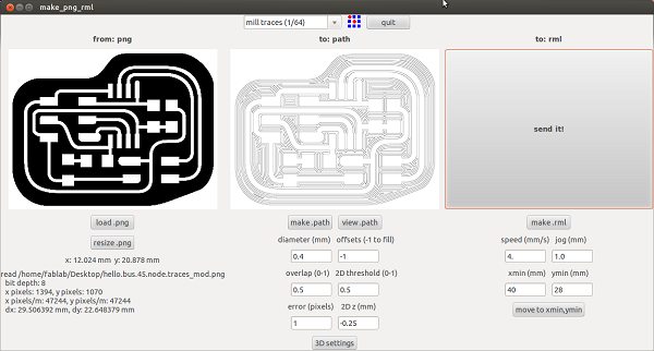
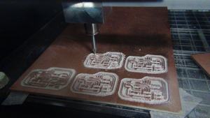 The milling process with the conical mill The milling process with the conical mill |
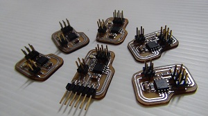
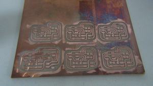 The final boards after sanding The final boards after sanding |
After this I cutted with the laser cutter and continued with the welding process like past assignments.
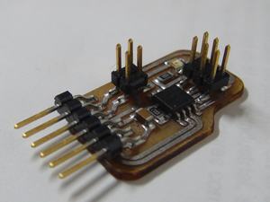 The bridge board The bridge board |
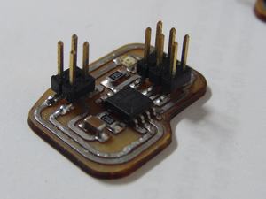 The node board The node board |
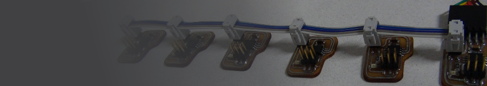
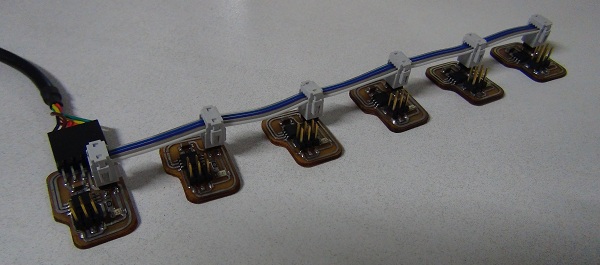 The 6 boards connected with the flat wire
Programing
The code of the program is below (I remove the definition part for the space):
// hello.bus.45.mod.c
// # Author: Toshiro Tabuchi - FAB LAB LIMA
//
// 9600 baud serial bus hello-world
//
// Modified from: hello.bus.45.c
// Original Author: Neil Gershenfeld - CBA MIT 11/24/10
//
// (c) Massachusetts Institute of Technology 2010
// Permission granted for experimental and personal use;
// license for commercial sale available from MIT.
//

--- In this place are the definitions of the original program ---
          (I removed because it occupy too much space)

int main(void) {
   //
   // main
   //
   static char chr;
   //
   // set clock divider to /1
   //
   CLKPR = (1 << CLKPCE);
   CLKPR = (0 << CLKPS3) | (0 << CLKPS2) | (0 << CLKPS1) | (0 << CLKPS0);
   //
   // initialize output pins
   //
   set(serial_port, serial_pin_out);
   input(serial_direction, serial_pin_out);
   set(led_port, led_pin);
   output(led_direction, led_pin);
   //
   // main loop
   //
   while (1) {
     get_char(&serial_pins, serial_pin_in, &chr);
     int chID = chr; //Converting the character to number
     int wait = node_id; //Converting the node_id to number
     if (chID >= wait) {
		 int cont = 48; // ASCII Number of the '0' character
		 for (cont ; cont < wait; cont++) { //
			 led_delay();
			}
         flash();
		 //Node mensaje//
		 output(serial_direction, serial_pin_out);
         const static char message1[] PROGMEM = "Flash ";
         put_string(&serial_port, serial_pin_out, (PGM_P)
           message1);
         put_char(&serial_port, serial_pin_out, node_id);
		 const static char message2[] PROGMEM = " - ";
		 put_string(&serial_port, serial_pin_out, (PGM_P)
           message2);
		 input(serial_direction, serial_pin_out);
        }
	//Condition for the final node mensaje//
	 if (chr == node_id) {
		 output(serial_direction, serial_pin_out);
		 const static char message[] PROGMEM = "END";
		 put_string(&serial_port, serial_pin_out, (PGM_P)
           message);
		 put_char(&serial_port, serial_pin_out, 10); // new line
		 input(serial_direction, serial_pin_out);
		}
    }
   }
* The function that generate the RGB code is call rainbow(val,rang). The val argument is the value of the variable, and the rang is the variable range. The variable value(val) has to start from zero and increase to the value of rang.
Testing
First I test the boards with the original program (check the correction of the original code in this link from AS200 Fab Lab).
Then when I sure that the circuit is good I test with my program. The leds flash in sequence starting in the bridge and ending in the node typed in the numpad. Also the nodes sends a mensaje to the computer: I.E.: Type "2" so the mensaje will be "Flash 0 - Flash 1 - Flash 2 - END"