Fab Lab Barcelona SuperNode /Fab Lab Sevilla /Jose Perez de Lama
hello.arduino.168 example and tutorial / part.02
[developed april/may 2014]
4./ Workflow & toolchain
Overall workflow is as follows (detailed step-by-step description further down in this tutorial):
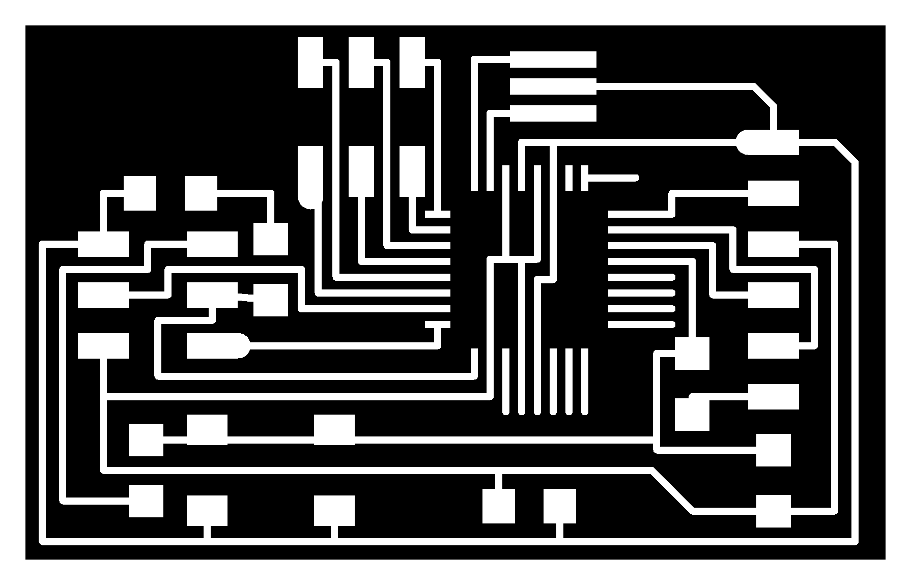
(1) Select PCB design to fabricate; from the available collection of boards of the Fab Academy classes. Alternately one could design his/her own board. The PCB design used here is the hello.arduino328 board, in particular the files used are traces png, board png where the components are listed. It is covenient to use the components jpg file as well to see a picture of an actually fabricated board.
(2) Generate the milling paths. You may generate the paths with Fab Modules. In this tutorial i recommend to postproduce the path file generated with Fab Modules with any 2D-CAD software in order to optimize the milling process.
(3) Machine-mill the PCB.
(4) Solder/stuff the smd components, following the board.png file.
(5) Debugg the soldering work using a multimeter, and resolder as needed.
(6) Bootload the firmware from your computer into the microcontroller(board).
(7) Upload the "blink" Arduino sketch to test if the board is working correctly.
Toolchain is composed by the following elements-systems:
(1) Select PCB design
Select an existing one already prepared by professor Gershenfeld as png to generate the milling paths with Fab Modules. Alternatively you could use available Eagle files (as for example in the Fabkit example). I believe Eagle can be installed in Ubuntu 13.10 from the Software Center. Otherwise you can download it from the Eagle web site. Here are further instructions to install Eagle in a 64bit Ubuntu 13.10 system.
(2) Generate the milling path
My approach for the hello.arduino baord was to use Fab Modules, png to dxf module to generate a dxf path file. In a Roland Modela MDX20 and more advanced models Fab Modules can be used directly to manage the milling process.
However, we are still using the Roland I-Modela and managing the process a bit differently.
From previous milling works using an I-Modela which has probably less precission than more advanced machines, my appreciation is that the files generated with Fab Modules make too narrow paths. So my approach is to open the dxf file with Rhinoceros (on a Windows machine) to modify and simplify the paths, making the board a bit larger, - a choice for beginners!
I also like to double-check the actual size of the components and pads using the corresponding data sheets. IMHO Fab Modules sometimes makes them a bit to tight for the I-Modela, specially because it makes closed loops and this generates double milling lines between the microcontoller pin-pads. It is useful to generate some design rules for this modification, for example, track width and optimal separation between tracks & component pads.
From Rhinoceros i export an .ai file (Adobe Illustrator) that can be imported by the I-Modela's own software, I-Creator.
(3) Machine-mill the board
To mill the board with the Roland I-Modela i use I-Creator and I-Controller, the Roland provided software that comes with the machine. With I-Creator one has to determine the position of the board plus milling parameters. I-Controller is used to set the x-y-z user coordinates. Special attention shall be paid to establishing the z zero coordinate, as boards are never prefectly horizontal. I like to "scan" a matrix of points on the board, in order to choose the lowest z and set it as the z=0 point. More instructions on these in the detailed process description.
FR1 board (phenolic paper base), softer to mill and ecologically friendlier than conventional boards, and 1/64'' end mill, are the recommended material and tool.
You can cut the perimeter of the board in a number of ways. Lately, to make it faster, we are doing it with a laser cutter, putting the board upside down, and then completing the cutting, if necessary, with a manual cutter, and file (lima).
(4) & (5) Soldering/stuffin the board and debugging
No software needed here. You need of course basic soldering equipment: soledring iron (40W, for example) with a rather fine tip, solder, vise and/or third hand, magnifier lamp, tweezers, flux and desoldering braid (just in case). I definitely recommed to have the board image in front of you to use it as a visual guide. Of course you will need the electronic smd components as described in the Bill of Materials below. (*) Check the fab inventory for both equipment and components references.
I would say that once the soledring is done it is absolutely necessary to check with a multimeter (continuity) all the components solderings, especially each of the microntroller pins which are the smallest and most difficult ones. This again you have to make looking at the board image. Take note of the solderings that are not working and resolder them.
(6) Bootloading the firmware
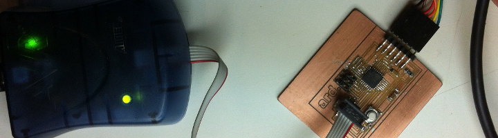
The bootloading (loading the firmware onto the microcontoller) is done using a combination of hardware and software. Gcc (C compiler for AVR microcontollers) and avrdude, the actual bootloader for AVR micros, and complementary libraries, make the software pack to be used. In order to bootload the micro you need a C sript with the actual bootloading instructions and a make file that runs avrdude. These files can be found in the Fab Academy class documentation. The hardware elements are the In-System-Programmer (here the AVR-ISP mkII, as mentioned before) and an FTDI (5V) cable that connects the board (FTDI port) to the computer.
GCC and avrdude are integrated in the Arduino IDE. Arduino IDE to be used should be version 1 or higher. In this tutorial version used is 1.0.5. Using the Arduino IDE makes the process a bit easier for non experts. Depending on the board you are fabricating, you might need a particular boards.txt file to add to the boards library in the Arduino IDE. This file can be found in the Fab Academy documentation. This will the case descibed in this tutorial.
(7) Upload the "blink" Arduino sketch to test if the board is working correctly.
In order to test the bootloaded firmware, the Arduino IDE is used once again to upload the blink skecth. This skecth is used because is works with the LED that is part of the board. The "blink skecth" is contained in the Arduino IDE examples folder.
Links
Part 01
0./ About this tutorial
1./ Description :: hello.arduino.168/328P
2./ Fab Academy reference files list and location
3./ Tutorials, info sources and URLs
Part 02
4./ Workflow & toolchain
Part 03
5./ System and software requirements & installation
6./ BOM (Bill of Materials) equipment and tools
Part 04
7./ Detailed fabrication process description
7.1/ Board preparation and milling
7.2/ Components soldering and debugging
7.3/ Bootloading firmware and uploading your first Arduino sketch (program)
Part 05
8./ Fabkit fabrication notes (files, ISP cables & connection)
jose_perezdelama @ Fab Academy 2013 final project
jose_perezdelama @ Fab Academy 2013 home page
Credits & license
This work is a derivative of documentation collected in the Fab Academy classes and tutorial pages authored by Neil Gershenfeld, Anna Kaziunas/AS220 and Fab Academy collaborators and students as mentioned in the corresponding linked pages for each of the sections.
Unless otherwise stated, information in these pages is downloadable under a Creative Commons Attribution-Share A Like license; attribution for the tutorial reorganization: Jose Perez de Lama / Fab Lab Sevilla / Fab Academy 2013(14).