Fab Lab Barcelona SuperNode /Fab Lab Sevilla /Jose Perez de Lama
Week 08 / embedded programming / 13.03.2013

[assigment]
Read a microcontroller data sheet. Program your board to do something, with as many different programming languages and programming environments as possible.
Class syllabus::
http://academy.cba.mit.edu/classes/embedded_programming/index.html
Links::
http://hlt.media.mit.edu/wiki/pmwiki.php?n=Main.AVRProgrammingAdvanced
http://www.ladyada.net/learn/avr/index.html
http://www.as220.org/fabacademy/tutorials/programming_FabISP.php#ubuntu
http://www.as220.org/fabacademy/tutorials/hello_echo_c.php
http://academy.cba.mit.edu/classes/embedded_programming/hello.ftdi.44.program.png
http://www.tutorialspoint.com/cprogramming/index.htm
htmaa 2012/
Travis Rich :: http://fab.cba.mit.edu/classes/863.12/people/travis.rich/week7/
Laia M-S :: http://fab.cba.mit.edu/classes/863.12/people/laia.mogassoldevila/projects/p6.html
Pip Mothersill :: http://fab.cba.mit.edu/classes/863.12/people/pip/WK7/wk7.html
htmaa 2011/
Mercedes Mane; assembly language ::
http://academy.cba.mit.edu/2011/labs/urbana/mercedes.mane/Website/Hello_World_Serial/index_hello_world_serial.html
Shahar Ronen; avr and phython ::
http://fab.cba.mit.edu/classes/4.140/people/shahar.ronen/avr_python_setup_guide.html
[assignment development]
This is being a difficult week... A very unknown territory for me, and "guides" and "maps" are intriguing but not easy to read, and somehow scattered around... For some reason i thought i was going to program the board in python, that i had been studying in the last weeks, but now it looks like i should do it in C, or in assembly language. Then, many examples i see have been done using Arduino as bootloader, which might be easier. But approaching the mythical C and microcode seems quite exciting...
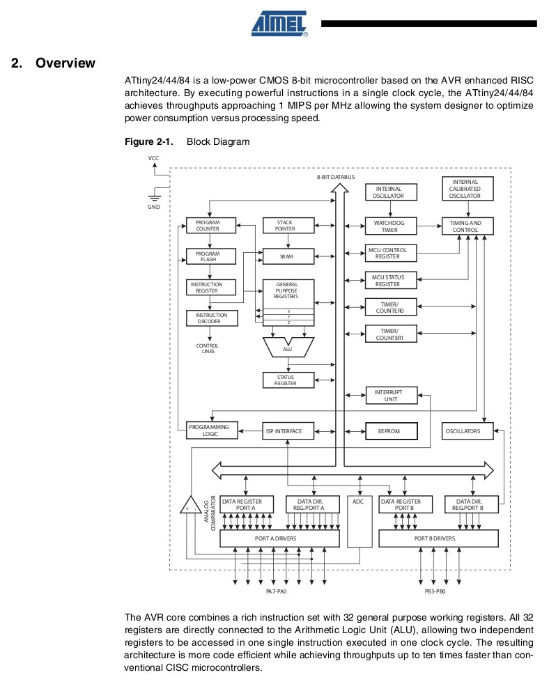
First of all i downloaded the ATtiny44 data sheet, the microcontroller we will be using this week, and tried to read through. It felt like the first time i read Deleuze and Guattari! Exciting, even though i couldn't make much sense of it! We discussed it in the lab, and had a robotic student over who explained us some. He seemed to be quite familiar with the stuff.
Then tried to understand the workflow of what we are supposed to do... I checked again the class, and looked through the projects of some of the students at htmaa 2012 and 2011: Pip Mothesill, Travis Rich, Laia Mogas-Solevila... Thanks for the documentation and links!
Then i googled avrdude, and got to a tutorial at ladyada on avr programming, and an MIT webpage, which i started working with. I wrote down here my own guide copy-pasting from these pages, as well as Anna Kaziunas' tutorials - thanks once again Anna!:
How to do something [http://www.ladyada.net/learn/avr/whatisit.html]
- Well first off you have to write a program (or have someone write one) that tells the chip what to do.
- Then you have to compile it, that is, turn the program description into machine code.
- Next you program the chip using a programmer, which will transfer the machine code to the device
- Test, debug, repeat!
From Anna Kaziunas'tutorial [installing avrdude, gcc and dependencies on Ubuntu; this was week 04's work]::
For the electronics units in the Fab Academy, you will need:
1. Avrdude (for programming AVR microcontrollers)
2. GCC (to compile C code)
Ubuntu instructions:
Get and install avrdude / GCC software and dependencies.
Open Terminal and type:
sudo apt-get install flex byacc bison gcc libusb-dev avrdude
Then type:
sudo apt-get install gcc-avr
Attention, if you are using Ubuntu 10.04, as i am, check the debugging section at the end of this post.
- type "y" when asked to do so by your system
Then type:
sudo apt-get install avr-libc
Then type (may already be installed):
sudo apt-get install libc6-dev
// The last part is for the ISP programmer.
// Download and Unzip the Firmware [which firmware is it?]:
// Move to the desktop:
// cd ~/Desktop
// Download the firmware from the Fab Academy Electronics Production page [this is the ISP // board firmware...].
// wget http://academy.cba.mit.edu/classes/embedded_programming/firmware.zip
// Unzip the firmware
// unzip firmware.zip
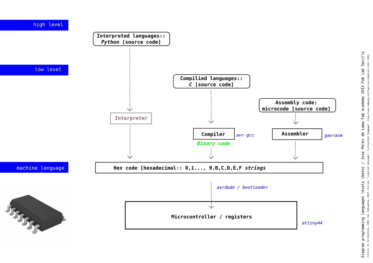
To make myself the workflow a bit clearer i made this map of high level, low level and machine languages. I had pencil sketched something similar the first time i read Neil's Fab. It has some, or rather many, issues i am not sure about. Please consider it an alpha version, and tell me the changes it should include. After the end of the week i realize the interpreter, compiler and assembler are outside the microcontroller?
"Are the interpreted and compiled languages assembled or do they interact directly with the micro?" was another of the questions. Now i think they don't need to be assembled, as in the compiled .hex files in C. So i will redraw this map for next weeks, but i still was useful to think about the process. The assembler, as well, is on the side of the computer and not in the microcontroller. In the cases i have seen, the assembler used is gavrasm.
[work plan and assignment work flow]
So a preliminar plan of what to do [made up around Friday] was as follows:
[00] Read the ATtiny44 data sheet.
[01] Install avrdude [that i hadn't done on week 04].
[02] Find out if an FTDI driver has to be installed. After a while i realized the driver was either part of the avrdude installation or already installed in Ubuntu [10.04].
[03] Find a similar c file than the one i need [according to the board made on week 06], study it and customize if needed.
[04] Compile the C file. First i thought this would be done with avr-gcc, and then i realized it could be done with Neil's script, which includes the avr-gcc step [the file linked in the next step].
Open the terminal and go to the directory where the file is and type:
make -f hello.ftdi.44.echo.c.make
A relevant issue that took us some time to understand, is that with this script you are compiling whatever c file you put in in its first line, under the parameter
PROJECT=name.of.the.project
The name of the file seems to go without the extension.
This will generate a .hex and .out file. Not sure what the .ou file works for. I have seen somewhere else it is a default extension when you compile a C file, to run it for example in your own terminal.
[05] Configure the ATtiny44 to run at 20 MHz[?] using the Xtal [setting the fuses] using again NG's in the terminal and Anna K's instructions. This file we slowly found out is a script that includes the succesive steps to be performed, But this we onlye find out towards the end., as explained in the class files.
Connect the AVRisp2 or FabISP to ftdi board with connectors and ribbon cable, and both to power [through usb ports?]. The order of connection seems to be relevant. In our case, this time we are using the AVRisp2. First connect the FTDI connector to the hello board; the black cable goes to ground. Second, connect the board to on of the computer USB ports. Third connect the hello board to the AVRisp2 using the ribbon cable; in our case the red cable and arrow goes to the VCC port of the ISP connector. Eventually connect the AVRisp2 to the computer with the USB cable.
Then, go to the directory where the files are and type in the terminal:
sudo make -f hello.ftdi.44.echo.c.make program-avrisp2-fuses
This script, it seems to me onlye performs this line:
avrdude -p t44 -P usb -c avrisp2 -U lfuse:w:0x7E:m
So in a way, it is independent on the file you are actually going to bootload.
[06] Load the c program in the microcontroller using avrdude [software], and the ISP board or AVRisp2 [hardware]. In our case AVRisp2. This step is made in a single one together with [5] using NG's c.make file.
sudo make -f hello.ftdi.44.echo.c.make program-avrisp2
The line in the script that performs thsi task is:
avrdude -p t44 -P usb -c avrisp2 -U flash:w:$(PROJECT).c.hex
[07] Test it. First one can check if the code has been loaded as suggested by NG, using the terminal and typing:
python term.py usb 115200
This actually didn't work for us even if we loaded some libraries. But we didn't devote a lot of time to this.
Then test the LED + button.
Ok, it worked for one of the boards, on an Ubuntu 12.04 machine _ the "DIWO other project" / versus de DIY. See pix and comments at the end of the page.
But then it didn't work with any other board and with any other computer.
[08] Debug, in case it doesn't work.
Still debugging, the second and third board... With many questions. See at the end of this page.
[09] Document
[10] Additional work that would be very desirable: make a fabduino. Not initiated yet...
[general info ATtiny44]
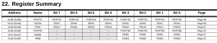
Some selected diagrams from the Atmel data sheet:
Summary of charecteristics, p:1

I/0 pins diagram is showed at the beginning of this page.
¿Hardware mico-architecture? p: 4
Port registers, p:266
Port functions diagram, p:54

Port alternate functions diagram, p: 58
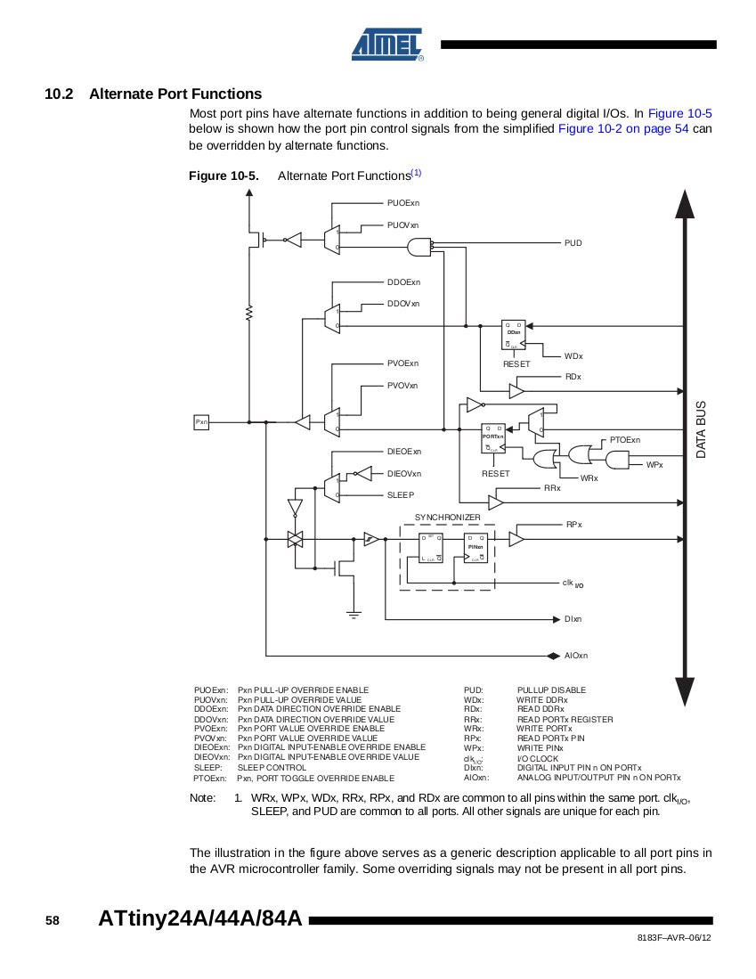
Control signals pin values, p: 55. Here the Tri-state, i don't understand so well;
The basic idea as we will see later on is that PORTxn = 1 means the pin is HIGH while PORTxn = 0 means it is LOW; while DDxn = 1 means it is an output pin, and DDxn = 0 means it is an input pin. Still i am not sure if the pull-up resistor is used in the script i am recycling to "block" the LED pin when the button is not pushed...

And this to check the I/O ports and pins that i will be using is the board i am trying to program:
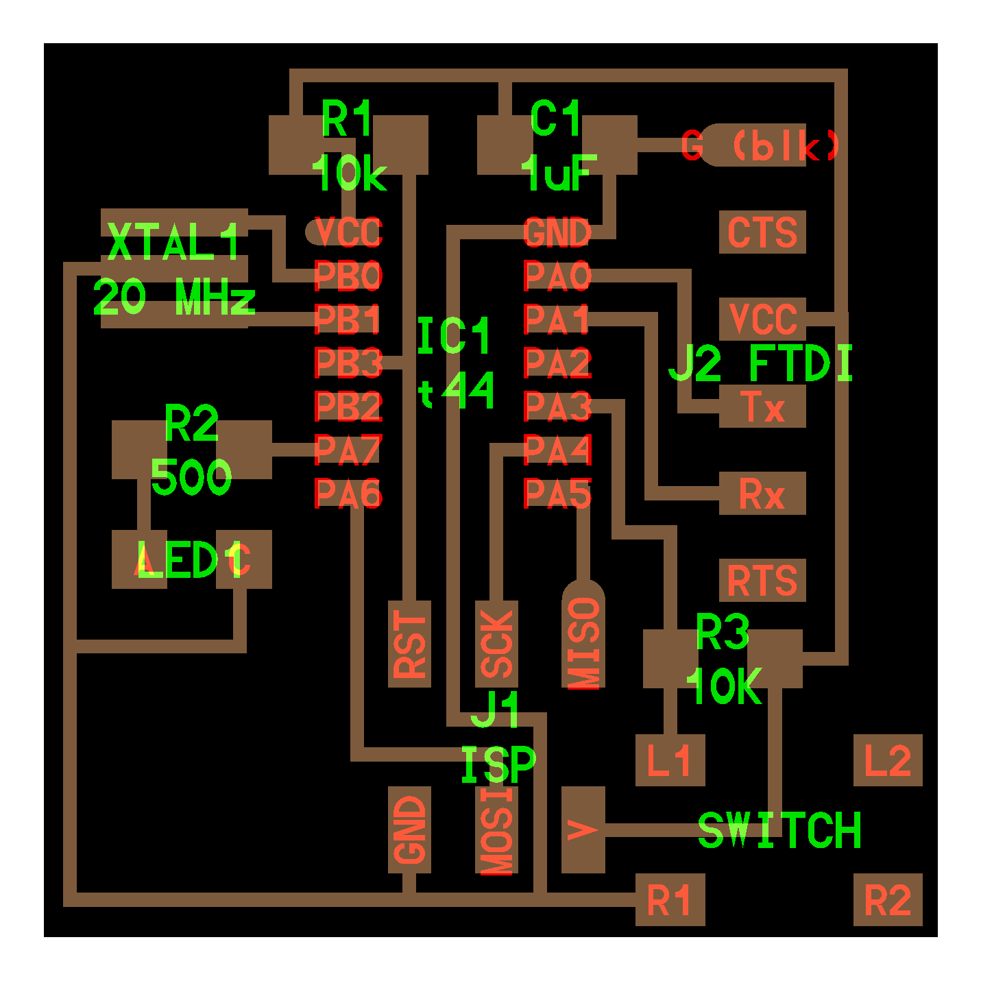
[C coding]
The pins i am using are PA7 to light the LED, and PA3 which is connected to the switch.
This would be the Arduino code for this board, to light the LED when the switch is on; thanks to Natalie Haddad. It is rather straightforward compared to the c code i have been looking at in different references:
const int buttonPin = 3;
const int ledPin = 7;
int buttonState = 0;
void setup() {
pinMode(ledPin, OUTPUT);
pinMode(buttonPin, INPUT);
}
void loop(){
buttonState = digitalRead(buttonPin);
if (buttonState == HIGH) {
digitalWrite(ledPin, LOW);
}
else {
digitalWrite(ledPin, HIGH);
}
}
Source: http://academy.cba.mit.edu/2012/students/haddad.natalie/embed.html
The difference with the C code, i guess considering Neil's explanations in class, is that Arduino [integrated c] libraries solve many of the things you have to write yourself if you do it in C, things such as describing the pins / registers you will be using and how you want to use them...
A simple piece of code in C just to light an LED looks like this:
#include <avr/io.h>
int main(void)
{
DDRB = 1;
PORTB = 1;
}
Source: http://www.nongnu.org/avr-libc/user-manual/group__avr__io.html
"This header file avr/io.h includes the apropriate IO definitions for the device that has been specified by the
-mmcu=
compiler
command-line switch. This is done by diverting to the
appropriate file <avr/ioXXXX.h>
which should never be included directly. Some register
names common to
all AVR devices are defined directly within <avr/common.h>,
which
is
included
in <avr/io.h>,
but
most
of
the
details
come
from the respective include file."Not so complicated either... up to now.
But here it does get more interesting, or tricky... PortB, which would be indeed mine, in both cases, is defined by eight registers, and you need to point to the right one, and you have to do it using bits and bytes...
Registers
[source: http://hlt.media.mit.edu/wiki/pmwiki.php?n=Main.AVRProgrammingAdvanced]
"Most of the bytes in the microcontroller's memory are used to store numbers and other data, but a few have special meanings. Some of these special bytes are called registers and they control the behavior of the various components that are contained in the microcontroller. These registers are bytes, but we don't use them as numbers. Instead, each of their eight bits has an particular meaning. The program above used two registers: DDRB and PORTB. These registers control the behavior of the eight pins of port B (PB0 to PB7):
- DDRB is the data direction register for port B. It determines whether each pin is an input or an output.
- PORTB is the data register for port B. For output pins, this determines whether the pin is set high or low.
Here's an example:
| Pin | PB7 | PB6 | PB5 | PB4 | PB3 | PB2 | PB1 | PB0 |
| DDRB | 0 | 0 | 1 | 0 | 0 | 0 | 0 | 1 |
| PORTB | 0 | 0 | 0 | 0 | 0 | 0 | 0 | 1 |
Here, pins PB0 and PB5 are set as outputs. PB5 is set low, PB0 high. That means that if you measured the voltage on PB5 leg of the microcontroller with a multimeter (with the other probe touching ground), you'd get 0V; if you measured PB0, you'd get 5V."
Comparing with the arduino sketch, i would need to set Pin PB7 as output, and Pin PB3 as input. Something like this, - with Pin PB7 set High in the table below.
| Pin | PA7 | PA6 | PA5 | PA4 | PA3 | PA2 | PA1 | PA0 |
| DDRA | 1 | 0 | 0 | 0 | 0 | 0 | 0 | 0 |
| PORTA | 1 | 0 | 0 | 0 | 0 | 0 | 0 | 0 |
Using the macro suggested in the tutorial i am following this could be done like this:
#include <avr/io.h>
int main(void)
{
DDRA = _BV(PA7);
PORTA = _BV(PA7);
}
This code, i think would point to PA7, and... give PORTA7 a value of one, therefore putting it High.
Notes, from the same source:
"Some of the newer AVRs contain a System Clock Prescale Register (CLKPR) that allows you to decrease the system clock frequency and the power consumption when the need for processing power is low. Below are two macros and an enumerated type that can be used to interface to the Clock Prescale Register."
Notes, continuing with the same source:
To understand this program, we need to know more about bit math, various operations that manipulate the value of a byte. There are five basic operations: left-shifting (written <<), right-shifting (>>), bitwise-or (|), bitwise-and (&), and bitwise-negation (~). See also: http://www.microbuilder.eu/Tutorials/Fundamentals/Bitwise.aspx
and http://www.nongnu.org/avr-libc/user-manual/io_8h_source.html
Shifting bits like this and 'inserting' them with the "|" OR operator is an exceptionally common task when working with embedded software (since you often need to manipulate individual bits to turn features on or off or to configure your peripherals).
See also I/O ports in the ATtin44 data sheet:pp:53-67, 266
This then after some time reading and comparing things, is the code in C that i will start testing. It is directly based on htmaa 2012 student Travis Rich's, which is based on Neil's hello.arduino.168.blink.c file. I was checking Tarvis's board and it is quite similar to mine, just with two LEDs instead of one. I tried to understand what each line of code performs, checking the Atmel data sheet, a C tutorial and various other sources. I still don't understand it all the way, but i think it will work. I commented it thorougly; many of the comments rather being questions:
// Jose Perez de Lama Fab Academy 2013 17/03/13
// hello.ftdi.led.button.beta.jpl.c
// customization and comments on:
// Travis Rich 10/22/12
// an iteration on top of the following attribution:
//
// hello.arduino.168.blink.c
//
// test blinking LED
//
// Neil Gershenfeld
// 3/14/11
//
// (c) Massachusetts Institute of Technology 2011
// Permission granted for experimental and personal use;
// license for commercial sale available from MIT.
//
#include <avr/io.h>
// avr input output preprocessor library
#include <util/delay.h>
// time management preprocessor library
// Following with #define preprocessor macros probably associated to the avr/io.h library
// i have tried to find the source code for avr/io but eventually this task had to remain in the todo list
// plus macros associated to the util/delay.h library
// The following macros use bitwise operatiors to activate, disactivate or test the DDRxn, PORTxn and PINxn registers
// PORTx, Data Direction Register DDRx, and the Port Input Pins PINx; Atmel data sheet p 53
// It would be necessary to better understand what each of these macros exactly does
#define output(directions,pin) (directions |= pin) // set port direction for output
#define input(directions,pin) (directions &= (~pin)) // set port direction for input
#define set(port,pin) (port |= pin) // set port pin
#define clear(port,pin) (port &= (~pin)) // clear port pin
#define pin_test(pins,pin) (pins & pin) // test for port pin
#define bit_test(byte,bit) (byte & (1 << bit)) // test for bit set
#define led_delay() _delay_ms(5000) // LED delay i extended it to 5000 before it was 1000
// setting the port registers DDRxn PORTxn PINxn
// led output
#define led_port PORTA
#define led_direction DDRA
#define led_pin (1 << PA7)
//button input
#define input_port PORTA
#define input_direction DDRA
#define input_pin (1 << PB3)
#define input_pins PINA
int main(void)
{
//
// main
// set clock divider to /1
// CLKPR Clock Prescale Register Atmel data sheet pp 30 32 103
//
CLKPR = (1 << CLKPCE);
CLKPR = (0 << CLKPS3) | (0 << CLKPS2) | (0 << CLKPS1) | (0 << CLKPS0);
//
// initialize LED and button pins as output and input
//
clear(led_port, led_pin);
output(led_direction, led_pin);
//
// In addition, the Pull-up Disable – PUD bit in MCUCR disables the
// pull-up function for all pins in all ports when set. Resistor associated to every pin
// Atmel data sheet p 53
// i am not sure if this is what the clear macro performs as it was commented on the file
//
clear(input_port, input_pin); // TR turn on pull-down
input(input_direction, input_pin);
//
// section of code that was outcommented by TR
// main loop
//
// while (1) {
// set(led_port, led_pin);
// led_delay();
// clear(led_port, led_pin);
// led_delay();
// }
// }
//
while (1)
{
// i dont understand the (1) parameter it seems to be a permanent pre-given condition
// TR wait for button down
//
if (0 != pin_test(input_pins,input_pin))
{
clear(led_port, led_pin);
led_delay();
// this seems to turn the led on, that is give PORTA7 the logic value of 1 / HIGH
// it seems to be triggered by pin_test = 1 which should mean the button is pressed
// maybe it is through removing the internal resistor at PINA7
// but maybe this is wrong and it works the other way around and no pull resistor is involved
// clear meaning then that the logic value is set to 0, and set, that it is set to 1
// and then the if loop would work the other way around
// this would be like in the arduino sketch the i reproduced above in this page
}
set(led_port, led_pin);
// this then might return to pull up the resistor this condition seems to happen when pin_test = 0
// or rather, after the second hypothesis it would turn the led pin HIGH
}
}
[compiling, bootloading]
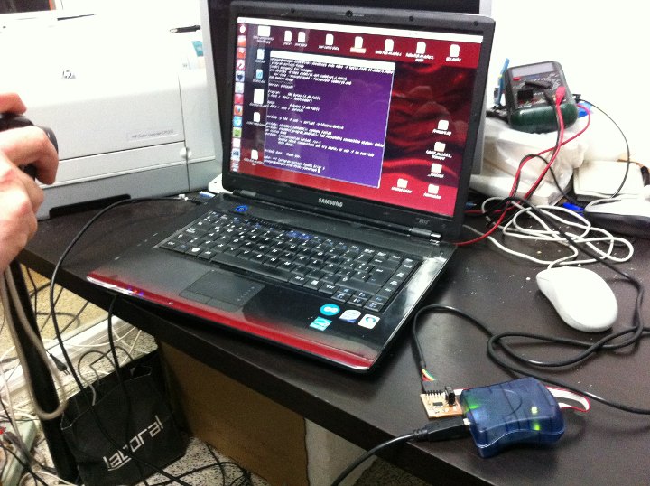
Monday, we were still rather lost, and we got together to try to make it happen. A friend of Juan Carlos Venegas, Alejandro Campos, a graduate student in robotics at the University of Sevilla came over and was of great help.
After several trials with JC Venegas computer, and using Neil's make file we managed to compile the file that i had prepared during the weekend, then set the fuses, and eventually bootload the program in one of the boards we had made on week 06. It actually was JC Venegas' board. We were extremely happy! Here is a picture of the team right after lighting the LED.
The board works like this. You press the button, and after 5 seconds, the light shines. While keeping the button pressed the LED remains on. Once you unpress the button, the LED immediately turns off.


[debugging the second board]
As mentioned above, we haven't been able yet to make a second board work; the hello board that i designed and soldered together with Juan Carlos Perez two weeks ago. First, the AVRisp2 didn't flash green. So we returned to examining the board soldered connections. This i did with Jose Buzon. We cleaned some of the connections that looked bad and resoldered them. We tried again and it flashed green!
But then... I had to spend some hours trying different things... but couldn't make it work yet. The error that was kind of stabilized at the end is the one in the screenshot below [2nd image]. I googled it and realized it was a non unfrequent situation, but haven't found out yet the solution.
I was checking my etc/avrdude.conf file and was surprised in different ways. First of all i hade three avrdude installations, one associated to arduino, another to replicatorg, and then the most recent one, which was actually in the bin folders. The i had a second avrdude.conf file inside the arduino...
Secondly, in my etc/avrdude.con file the ATtiny44 doesn't show up in the #def section with the other micros. However it is in the part description. Following some google leads i tried to modify the conf file... But didn't succed eliminating the error...
As usual it will probably be some much more trivial mistake... Let' see.

[debugging continued / 22.03.2013]
// gcc-avr with Ubuntu 10.04
After serious googling, and multiple tries, i found out that the default gcc-avr [v 4.3.4] installed by Ubuntu 10.04 doesn't include code for the attiny44... Hmmm... Installing gcc-avr in Ubuntu 12.04 should work right away, but not with Ubuntu 10.04 - which was the latest LTS version before 12.04. Installing a newer version of gcc-avr took me a while... Eventually i found the link - and downloaded a 4.5.1 version of gcc:
http://www.wrightflyer.co.uk/avr-gcc/
I uninstalled the default one that i hade been unsuccessfully trying, using synaptics, just in case, and installed the new one [that you can do sudo dpkg -i package_file.deb ] or just following the automatic installer after extracting the zip file, which is what i did.
The file doesn't install itself in the "right" place, to prevent from smashing other compilers that could be already installed. If one tests the make command, it doesn't find avr-gcc. Reading various sites i realized that you have to give it the path, but didn't understand how exaclty it should be done; until i read here:
http://www.linuxfocus.org/English/November2004/article352.meta.shtml
I think this is some kind of "direct access" or virtual link. First, one should check whether there is a folder such as /usr/local/avr/bin.
In case ther is not one should create it anew:
sudo mkdir /usr/local/avr
sudo mkdir /usr/local/avr/bin
In my case it was already there.
Then you type in the terminal:
export PATH=/usr/local/avr/bin:${PATH}
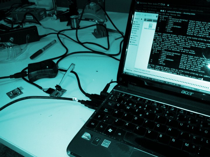
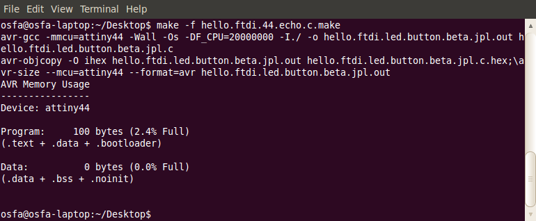
Then, eventually, after a couple of days, i was able to type:
make -f hello.ftdi.44.echo.c.make
and the file actually got compiled!!! The attiny code had been incorporated and now i will try to connect it the the actual attiny44 for my second board... And i believe it will work. But then i have to study the board, because testing it with another computer, it didn't work, and the errors seemed to suggest some connections were wrong...
[additional work and comments]
Something to be taken into account is that the default installation of gcc-avr for Ubuntu10.04 LTS doesn' include drivers for attiny44 and 45. Even is it is becoming now an old distribution, it would be nice that this fact had been known in advance. Manual installation of later gcc-avr versions has been problematic because it conflicts with other software components, for example arduino's own gcc-avr - i think -, and i haven't been able to get it to work in a stable mode. Then i installed Ubuntu 12.04 in another partition, but for some reason my Acer InspireOne has continous trouble with it. So i had to use one of my colleagues' Windows machine in the next assignments involving gcc-avr. All in all, i worked hard to get the avrdude-gcc tool chain to work, and got to understand it quite thoroughly.
In this class we managed collectively to make one board work. In later classes we programmed and bootloaded other boards individually, for example in the input devices class. This boards i bootloaded, as mentioned, using a Windows machine. Even if in the web page i show three different boards that we made in that class, my individual boardwas the hello.temp one; see link here: link>>
[files download]
Unless otherwise stated, information and files in this page are downloadable under a Creative Commons Attribution-Share A Like license; attribution: Jose Perez de Lama / Fab Lab Sevilla / Fab Academy 2013

# hello.ftdi.44.echo.c by Neil Gershenfeld [.c]
# hello.ftdi.44.echo.c.make, make file by Neil Gershenfeld [.c.make]
# ... [.c]
# ... [.hex]
More files coming soon
Software:: avrdude and avr libraries, gedit, gcc 4.5.1, C, NG's c files, macros and .h files
Hardware:: ATtiny44 microcontroller, hello.echo.ftdi.44.led.button[jpl] board, Avrisp II
//
previous class:: 07 molding & casting / next class:: 09 cc machining
return home /perezdelama.jose