Fab Lab Barcelona SuperNode /Fab Lab Sevilla /Jose Perez de Lama
Week 10 / input devices / 27.03.2013
[assigment]
Measure something: add a sensor to a microcontroller board and read it.
Class syllabus::
http://academy.cba.mit.edu/classes/input_devices/index.html
[preliminary comments]
This has been a collaborative work by José Buzón, Juan Carlos P. Juidias and myself. However, each of us has taken care of milling, stuffing and programming his own board. Buzón the hello.tempo.45, Juidias the hello.light.45 and myself the hello.txrx.45. Juan Carlos Venegas has joined at the end of the process reproducing the porgramming part on his computer.
Errata have been fixed after the class; python script loading which was missing a piece of code declaring the serial port connection, which could be seen however in the screenshots.
This has been the most difficult week for me up to now. Particularly with software/programming and electronics i have to begin every week trying to understand what we are supposed to do, then how, and eventually i try to give some thinking to the why... Microelectronics are indeed cool and extremely relevant to contemporary world, but i am having a hard time assuming why are we doing them so small [smd]... It feels much more like a machine task than a human one. And still... It is very attractive and challenging to work with this micro-scale...
This week, the idea of sensors, and later of actuators, seems quite straight forward. I had done some things with Arduino and they are fun, and one gets immediately captured by it. This week however things are much more complicated. I guess it has to do, on one hand, with trying to talk directly to the registers in the microcontroller instead of relying on prepackaged arduino or firefly libraries. On the other hand, with trying to implement more complex sensing processes, those introduced by Neil in his book Fab, that have to do with using one-bit A/D converters, on-chip S/H buffering and comparators, asynchronous undersampling and things like that. I went back to read Neil's Fab Instrumentation chapter in Fab, and listened again carefully to and took some notes of the video-recorded class. In order to understand it better i translated into Spanih "Instrumentation". Here is a link to it; i think it might be helpful for Spanish speakers to understand some issues more thoroughly [link to Instrumentation, translated into Spanish]. Here is the diagram that Neil made in the class to introduce a.u. in the case of the step response sensor. The idea is to use a simple and unexpensive A/D converter to measure an almost instanteneous process, by holding the data, and then reading them several times in different ways, or rather micro-moments of the process, and then comparing them...
[assignment development]
So, remembering, once again, the first class on project and time management, i decided that just trying to understand the various sensors and hello boards and reproducing one of them, would me more than enough of a task for me this week... Before beginning, i could see many steps were one could get stacked: [1] our PCBs aren't yet perfectly milled; [2] smd components soldering is still a very delicate task for usin the lab; [3] debugging boards with the multimeter another adventure into the unknown... [4] after loading the C program there might be an issue with the clock, Neil dixit, that would do the board not to work; and then some code tweaking should be tried with the help of an oscilloscope... [4] using the python terminal program to interact with the board is something still to be mastered... Besides, fully understanding the C programs, with all the libraries, macros, bitwise operations, clocks, A/D convertors, S/H module, comparators... seems something unattainable to achieve in a week, beyond a general idea of what the differents parts do...
So i would start studying and reproducing one, or two, hello.boards, not the easyest ones, though. And then see, in case of finishing soon if i can introduce some kind of variation... That was the idea. I chose to begin with one of the hello boards that i might be using in my final project - i did change my initial idea and now i am thinking of some kind of "digital garden"; and then follow with the second one, the step response sensor. I was already quite fascinated when i read Fab that the sensor could indeed sense the proximity of a body before it even touched it; and Neil's ellaboration on it in the classs really captured my imagination, and that of some of my lab mates.
[generating the PCB files and milling]
To generate the milling files, - that i would be milling with the iModela with the not-so-good angled mill, i used fab modules cad & png to dxf, and then Rhino to tweak the paths a bit, giving some more space to the components and tracks, then exported the files to .ai, and eventually used iModela Creator and iModela Controller to drive the actual milling process.
I had to mill a couple of boards because i haven't gotten yet the perfectly right parameters for the boards and the iModela: It might also affect that the end mill seems to be close to its life end...
I was also studying the hello.arduino.168 board, from last class. As C is becoming more and more "abstract" i am afraid i will have to test making my final project with Fabduino... I was also researching the equivalents of smd components and through-hole ones. If we keep having trouble with the tiny boards, i am thinking it could be a good idea to try them first with breadboards and through-hole boards, and in this way advance in parallel with hardware and software. Otherwise we have to wait until we have a working board to begin with software...
So here are some screenshots and pics of the hello-boards preps, and milling process, showing various not-so-perfect results. I think most of them can work, but i am just a bit stubborn... Again, this week was a serious holiday in Spain, but tomorrow i will talk to the Roland people in Barcelona, thanks to a contact made by Tomas in Fab Lab Barcelona, and see if they can send us a new collet and some 1/8" shaft end mills that fit in it. That woukd make our fab-lives so much better!
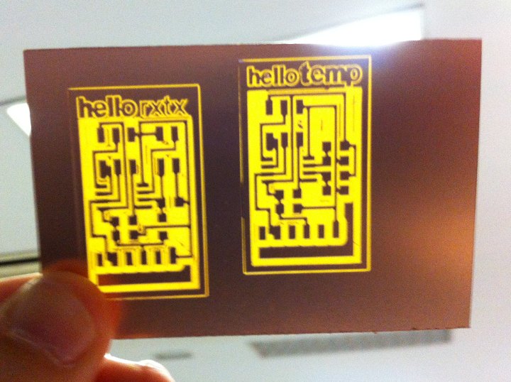
After milling 3 + 2 + 2 boards, i got two with which i am quite, quite satisfied. I would say they are 85% perfect. The process and parameters has been like that - using Ubuntu 10.04 fro Fab Modules, and Windows for Rhino and iModela.
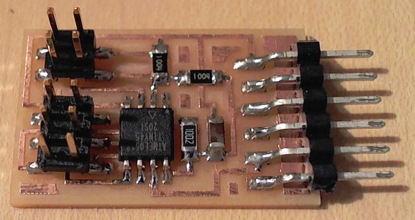
Downloading Neil's hello.tx.rx.45 files. This is Neil's model board stuffed with its components:
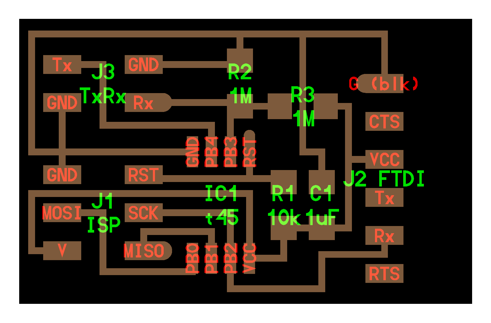
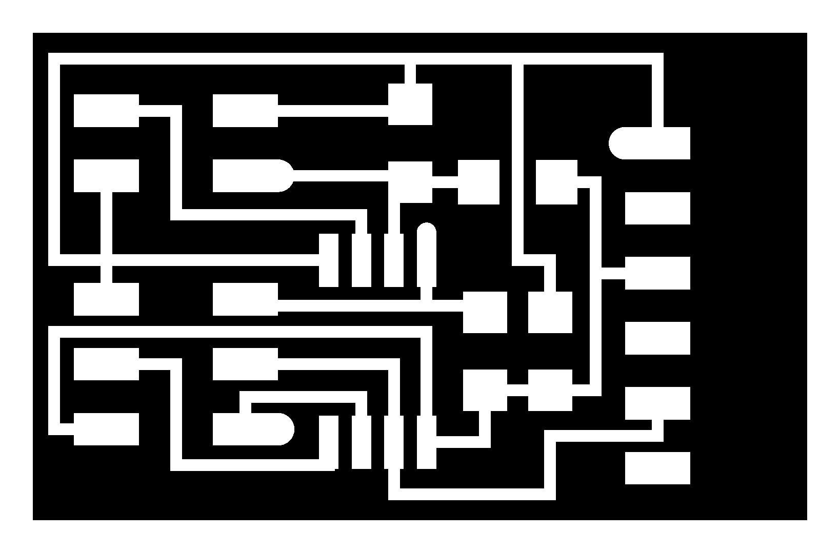
These are the board diagram and traces versions of the png that can be genearted with fab .cad-to-png module:
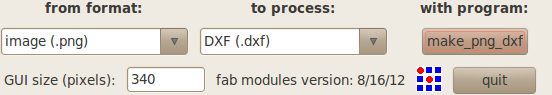
Opening terminal and then fab png-to-dxf module:
Then, generating paths. Choosing the right values for parameters is the key issue in the process. Parameters that have given the best result are the following:
Diameter = 0.4mm [our mill is nominally 0.2mm, but with a 45º angle profile]
Offsets = 6 [this value fills most of the empty spaces and making it 6 rather than the default value of 4 is just to make the board look better]
Overlap = 0.5 [tested various values and this, again the default one, works quite well]
Error (pixels) = 0.8 [tested 0, and it does generate a nicer layout, but the file is much heavier and difficult to process]
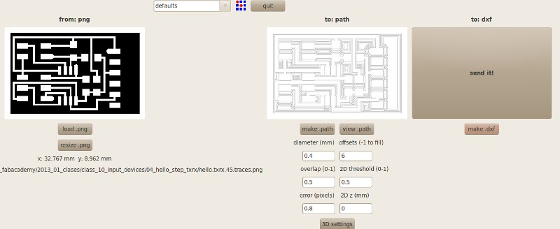
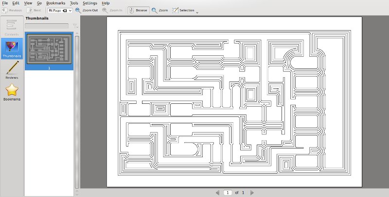
The path png file can be checked in detail clicking the "view.path" button, which opens an Orakular window - one of the dependencies that we installed in the beginning of Fab Academy.
Eventually, back in fab modules, clicking "make dxf", fab generates a .dxf file, that is saved in the location you opened fab from, in my case, the home folder. If you are testing the software, as i still am, its is convenient to rename o move to well ordered folders the succesive versions, because otherwise the names become a bit confusing.
So, now, because fab-send we haven't been able to master fab-send-to-iModela yet, and because of the particualar - bad - performance of the 45º angles mill, i process the file a bit through Rhino, to widen some spaces between paths that didn't come out well in earlier tests, and to generate an .ai file, that i can feed in the iModela software. I also use Rhino to put some lettering on the board.
The process in Rhino, after three different tests, works quite well as follows. Import dxf. Here you have to pay attention to units. My fab module generated files are in inches. You can change this in the .cad file, but for me it is easier to do it in Rhino. I go to "Properties" and find "/Units" and "/Page Units" and change both to mm. Rhino asks if i want to change the size of the file multiplying its dimensions by 25.4 and i say yes. At the end of the process when exporting to .ai, Rhino will ask again and you have to confirm or actually fill that 1mm = 1mm; - the iModela takes units in mm.
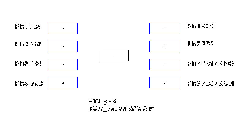
In Rhino, just because i like to make things slowly and as thorough as possible, i had drawn the ATtiny dimensions, the pads. To do this i took Neil's .cad file where he specifies the pads dimensions and topology in order to generate the fab files. I did this to double-check the distance from the first offest generated by fab modules to the actual pad profile. This distance is suprisingly not 0.2mm. This i think might be related to the overlap value... It is rather 0.149 mm. So i joined all the curves, and made an "Offset" towards the outside of 0.06, that gave me an initial offset of the first path slightly bigger that 0.2mm. Then i checked if there were some conflicts with overlapping paths that would generate some visual or actual problem making some areas thinner than they should be. I fixed some minor situations "by hand".
Then i generated the texts. I think they do look nice, and that is is quite convenient to be able to easily recoginze in the future what the board is about. Texts i have to improve, but i tried to generate some standard for my self with sizes and offsets, to use them in all the next boards.
Here are some images, of the ATtiny45V board, and the files tweaked in Rhino. Even if i am sure it might be boring to draw a board for someone who has made many, for a new-comer it is quite fascinating. You learn much better how it works. It made me think of the early Toyo Ito, who compared in the 80's the shape of the architecture and the city to come with the shape of microchips. In a way, he said, it was the informational version of the analogy moderns had made to mechanical machines. Btw, Ito received these days the Pritzker prize, which is usually described as the Nobel prize for architects. So...

Above, the aspect of ATtiny45 smd; below the geometry of its pads. The central pad is not actually there. It is the reference to draw it in .cad.
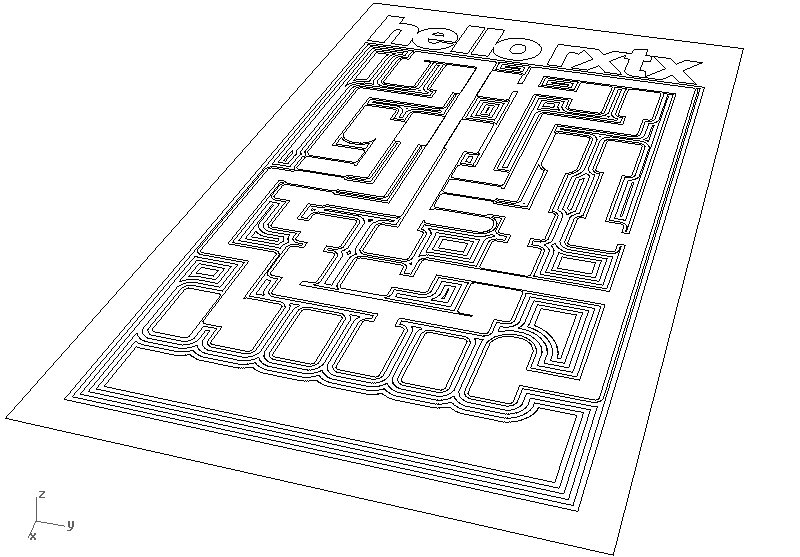
This is the cutting file of the hello.txrx.45 board before exporting it to .ai:
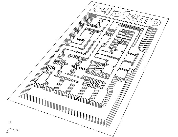
And this one the paths for the hello.temp.45 board ready for milling:
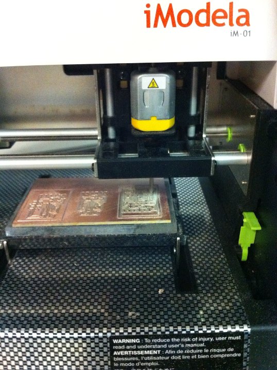
Then, i connected and turned on the iModela - on a Windows machine. Open iModela Creator, import the file, set the milling parameters. Some comments. The z axis works rather odd in our iModela. On one hand its precission is... not easy to determine. The machine is set to cut in 0.01mm depth steps, but it seems to cut much deeper. And we haven't been able to tell it to mill less than 0.1mm, which it makes when the step is set to 0.01 in ten steps. We just observe the iModela Controller and stop it when it finishes the 0.01 mm layer; or alternatively the 0.02 layer. In any case, iModela's 0.01 mm seems to be enough to mill the copper layer off.
For the latest boards i set the milling speed to 40 mm/min, in both roughing and finishing. We assume it uses the finishing configuration. Before, we had been using 60 mm/min. The depth step as mentioned i set to 0.01mm. This seem to be the main parameters. As we chose the engraving mode, the mill diameter doesn't seem to be so relevant. Still the option chosen is end mill - instead of angled, and 0.4mm diameter. End mill seems to allow for a better control of the cutting depth - for us.
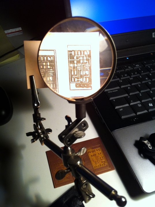
With this configuration i achieved a very good result in my first try. But somehow a little worse in the second board i milled. Here i got a lot of shavings. I believe this might be because the bit is loosing sharpness. I wonder, how long does a mill last? And how do you realize that it is over? So this are some pics of the milling process and results; first the not so good tests, some board examination with magnifying glass, and the final boards, num 6 actually, which i assume will be the one i will try to solder first...
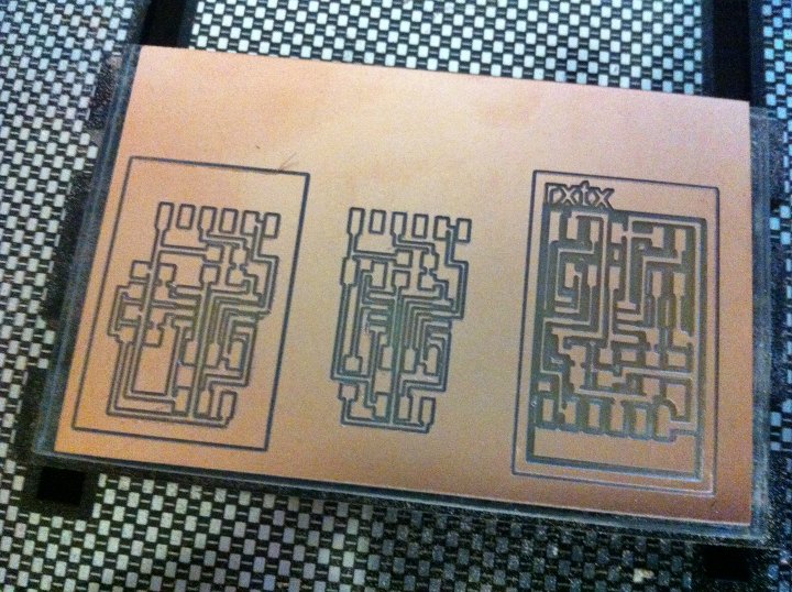
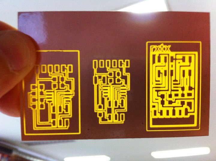
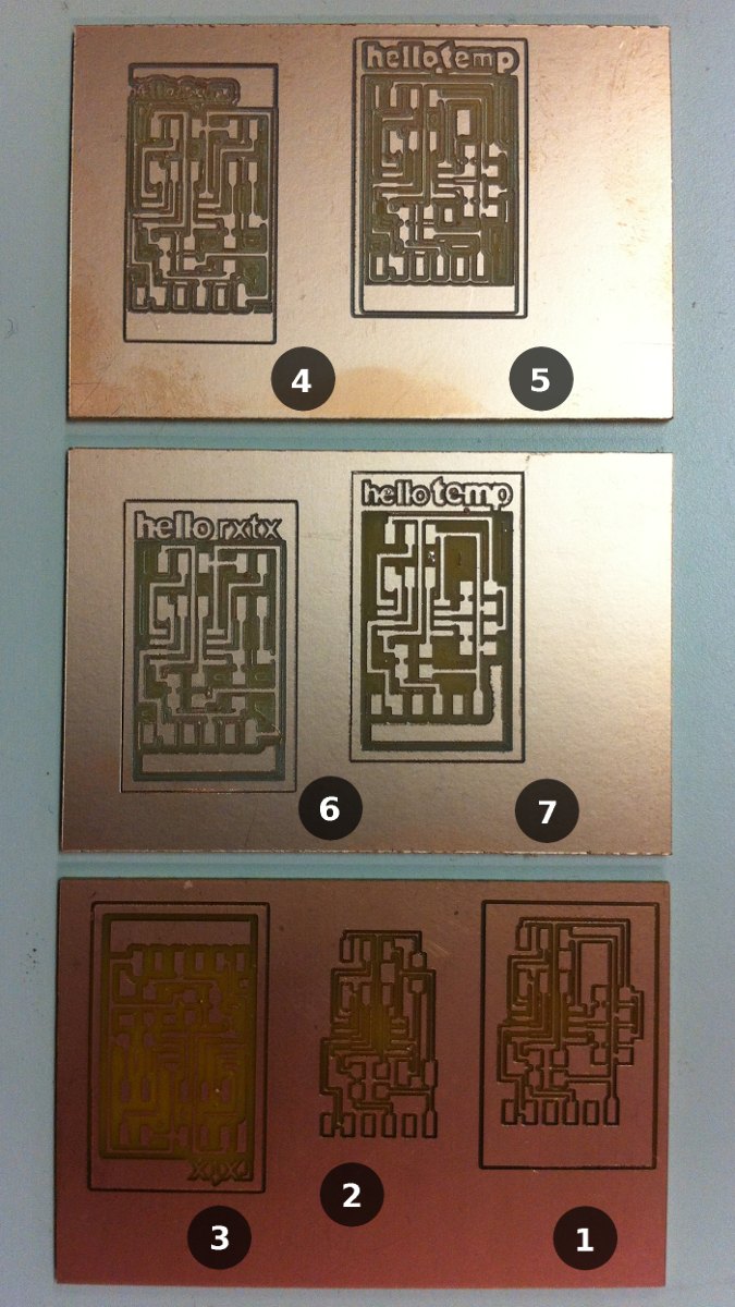
1 and 2 are tests by Juan Carlos Perez Juidias for hello.light.45 and hello.tempo.45. In 4 and 6 i used an overlap of 0.2, that didn't work. 6 and 7 i think are quite good, as can be seen in the image below.
[components]
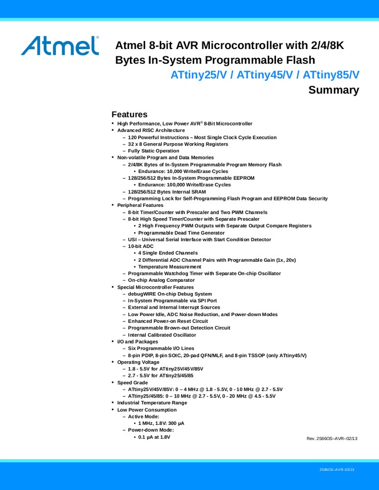
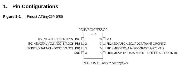
This week we are using ATtiny45V instead of ATtiny44 that we used in week 08. ATtiny has 8 pins instead of 14. It should be easier to solder!
These are the main features of the ATtiny45 from the data sheet, and its pin configuration:
The other components in hello.txrx.45 and hello.temp.45 are the following:
hello.txrx.45
| Component |
Digikey
reference |
| Microcontroller | |
| IC1
/ ATTINY45V-10SUND |
ATTINY45V-10SU-ND |
| Resistors |
|
| R1
10K / RES 10.0K OHM 1/4W 1% 1206 SMD |
311-10.0KFRCT-ND |
| R2
1M / RES 1.00M OHM 14W 1% 1206 |
311-1.00MFRCT-ND |
| R2 1M / RES 1.00M OHM 14W 1% 1206 | 311-1.00MFRCT-ND |
| Capacitors |
|
| C1
1uF / CAP CER 1UF 50V X7R 10% 1206 |
445-1423-1-ND |
| Connectors |
|
| J1
ISP / BERGSTIK HDR 6POS .100" DR SMT |
609-3487-1-ND |
| J2
FTDI / CONN HEADER 36POS .100 R/A SMD |
S1143E-36-ND
*
6 |
| J3
Tx Rx / BERGSTIK HDR 6POS .100" DR SMT |
609-3487-1-ND |
hello.temp.45
| Components |
Digikey
reference |
| Microcontroller |
|
| IC1
/ ATTINY45V-10SUND |
ATTINY45V-10SU-ND |
| Resistors |
|
| R1,R2,R3,R4
10K
/
RES
10.0K OHM 1/4W 1% 1206 SMD |
311-10.0KFRCT-ND |
| Thermistor |
|
| R5
NTC / THERMISTOR NTC 10K OHM 10% 1206 |
235-1109-1-ND |
| Capacitor |
|
| C1
10uF / CAP CER 10UF 35V Y5V 1206 |
587-1352-1-ND |
| Connectors |
|
| J1 ISP / BERGSTIK HDR 6POS .100" DR SMT | 609-3487-1-ND |
| J2
FTDI / CONN HEADER 36POS .100 R/A SMD |
S1143E-36-ND
*
6 |
[how the hello.txrx.45 board is supposed to work]
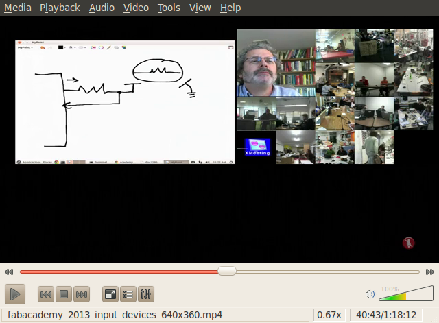
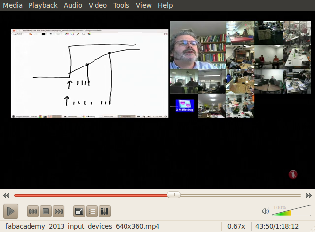
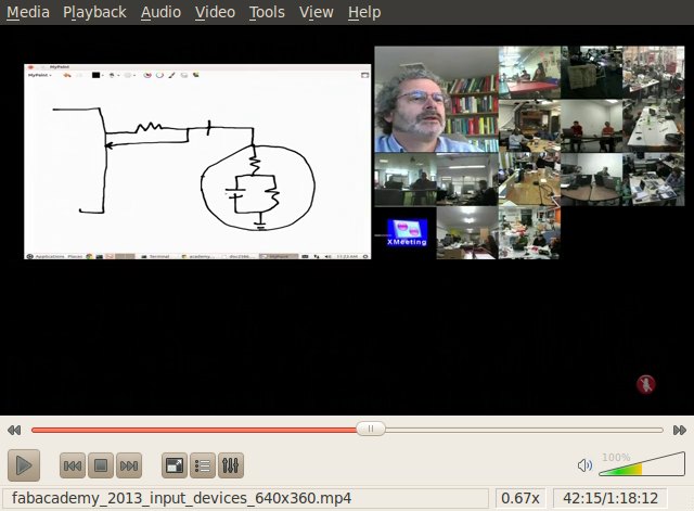
This is a screenshot of the class video, with a diagram Neil made explaining how the step response board works. A resistor comes out of the mincontroller with some voltage output to an electrode. And there is connection back that becomes an input to the microcontroller, sensing whatever changes might be in the electrode.
When, for example, a finger approaches, it modifies the electric field of the electrode, determining a voltage change in the input-return to the micro.
Bodies, in this case work as resistance - skin and actual interior body - and as a capacitor through our coupling with the objects and masses in the room we stand in. The value of our skin resistance is in the order of Mega-Ohms; of our internal body of Kilo-Ohms. As a capacitor coupled to the room we have a value in the order of Giga-Ohms. These are data from the class, if i understood them well.
So some people, like Neil, can model this and make the sensor evaluate, for example, proximity; or some qualities of the material that is approaching or touching the electrode[s]. The model diagram is as shown in the next screenshot; two resistors + one capacitor:
One thing that i really like, and surprises me in a way, is that the electrode can sense a body as it approaches, by sensing-measuring the variations in the electric-field / voltage produced by the approaching body.
But this, if i understood well, and i am not completely sure, is done through holding the data gathered during a fraction of a second - in the S/H [Sample / Holdd] part, and then choosing different moments of the process to send the corresponding data to the A/D converter, which again compares them to some reference... This, and maybe i am mistaken, is what makes the C files, more intricate than just gathering the raw data generated by a sensor... Or maybe not, and i am just imagining too much...
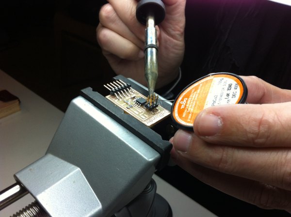
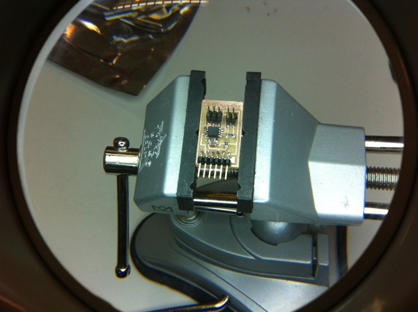
[stuffing the board & debugging]
Monday, with the team back from Eastern holidays was stuffing and programming day! I was not so convinced that things would come out easily... But they did! So quite early in the morning we planned the day, and started by selecting the components from our "digikey treasure box". We set up the vise, solder, soldering iron, tweezers, magnifying glass... and went for it. I began with the solder iron with Jose Buzon supervising the process, and then we exchanged roles. I soldered an txrx board and he made the temp. In the meanwhile Juan Carlos Perez was milling a couple of light.45 boards. And when ready he soldered it. Now we had three boards ready to program and we worked on them together.
[programming the boards and running the bootloaded programs]
The plan: Make file [compile] > make program [bootload in the microcontoller] > run rx.py to check raw output data in terminal > run python program to check data on visual interface.
At the end of week 08 i had achieved to solve some problems with avrdude and Ubuntu 10.04. After some long troubleshooting found out that the current version downloadable by 10.04 doesn't support ATtiny44. I had to update to a later version - as detailed in class 08 page, and set up a new path for avr. However the problems were back again; i was able to make the file after several tries, but then my terminal somehow couldn't find the path to avr. It kept saying it wasn't installed, even if i could see it was there. The older version and the new one. I thnk it might have to do with this. The installation from avrfreaks installs the second avr in an odd folder, which is actually a second bin folder inside usr/local/bin/avr and i think this confuses the system... I have to work quietly on it and see again what is going on...
To check if it was indeed a software problem, we moved to Jose Buzon's Windows machine, using cmd and the installation he had done some weeks ago following Anna Kaziunas' tutorial. We started with the hello.tempo.45 board. We went with the terminal to the directory were the files had been saved [hello.temp.45.make and hello.temp.45.c]. The C file was compiled right away with:
make -f hello.temp.45.make
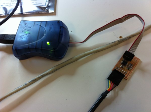
Then [1] we connected the hello board to the FTDI cable paying attention to connect the black cable to the GND pin, [2] the FTDI cable to the USB computer board avrisp2; [3] the hello board to the avrisp2 and [4] the avrisp2 to the computer USB port... and the green light shone! The connection worked. High fives!
Next, bootloading the compiled program into the board:
make -f hello.temp.45.make pogram-avrisp2 [no sudo in Windows].
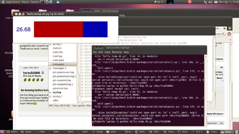
The message in the terminal said it had worked [above right :)]... Now we had to open the python script... But how? Back to Anna Kaziunas, some port name research... But the pyhton was not working... Something wrong with numpy...
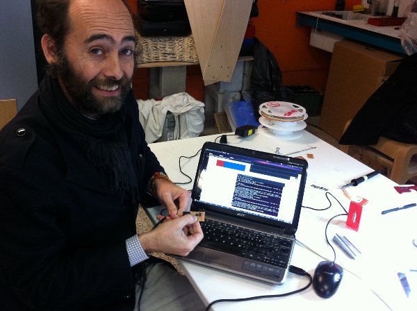
So a bit impatient, we tried opening it in the Ubuntu 10.04 machine and it seemed to work. Unplugged the board and plugged it again in the Ubuntu machine. Opened Administration/Log File Viewer/ messages to confirm the usb port name: /dev/ttyUSB0
With the .py file in the home folder, typed in terminal:
python hello.temp.45.py /dev/ttyUSB0
and, taking us by surprise, the visual interface opened in the desktop! Waaawww! Big high fives!
[debugging]
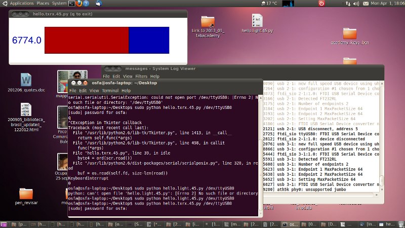
So, we went for the second board. Connected it to the Windows machine... and the Avrisp2 light came our red. Oooh! Dissapointment. It wasn't going to be that esay... So we tried the third board, the hello.light.45. It did light green! But then, it gave errors trying to bootload it. Hmmmm...
Magnifying glasses, and soldering iron. Buzon remade some of the joints that didn't look too good on both boards. Fixed one of the microcontroller leads that seemed to be loose... and back to connecting it to the Windows machine. First the hello.light.45. Avrisp2 green, and program loaded!
Ubuntu machine, second python script, and video interface. Some testing...
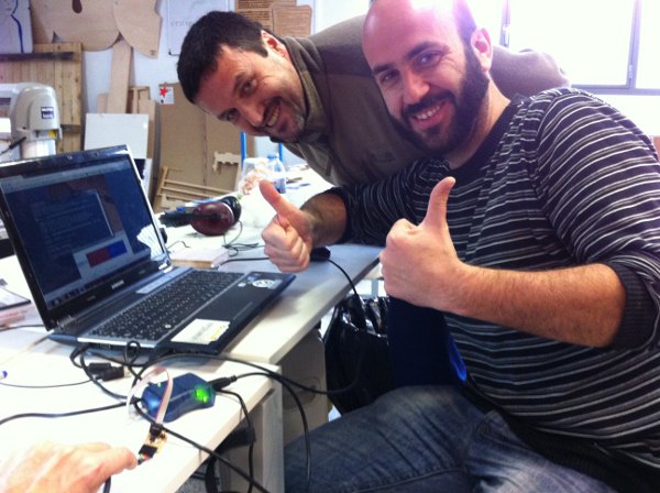
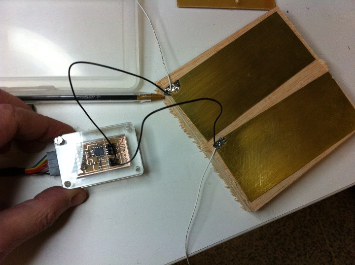
Eventually the third board, and it worked too! Great! We tinkered a connector for the tx and rx connectors. Not so sure how they should be connected. J3, with an rx, a tx and two ground pins... Tried to watch the little video... We tried to connect four wires to them, and solder one pair of each to a tin rectangle, but the data coming out didn't seem to change too much... We took the wires off, and tried touching the pins with our fingers, and this did make some significant differences, realizing that the pins making a change where the rx and tx but not the gound ones... So we unhooked the ground pins and started playing with the sheets of tin. Some fun! My favourite one at the end, was Juan Calos P touching one of the sheets and myself the other, and once we held hands we could see how the voltage changed significantly... It seemed like a great idea to work with for a final project.
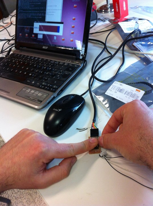 Hand testing the
hello.txrx.45 board
Hand testing the
hello.txrx.45 board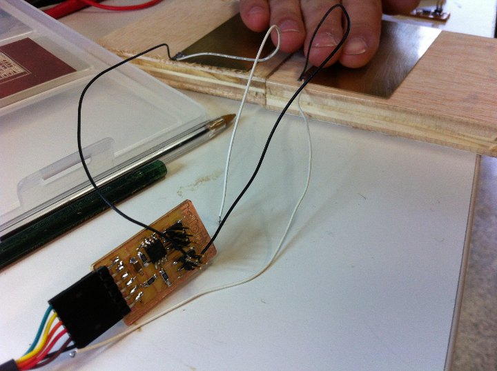
Eventually with only two cables to rx and tx pins we got the sensors to give significant outputs!
[sketching some boxes for the boards]
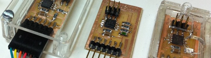
To end the day i joined Jose Buzon sketching and laser cutting acrylic boxes for the boards. They will be good to keep them clean and safe, and they look good. Of course we have to work a bit more on them - maybe with some parametric design, but it was cool to finish like this!
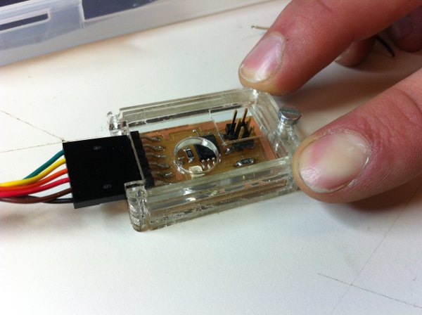
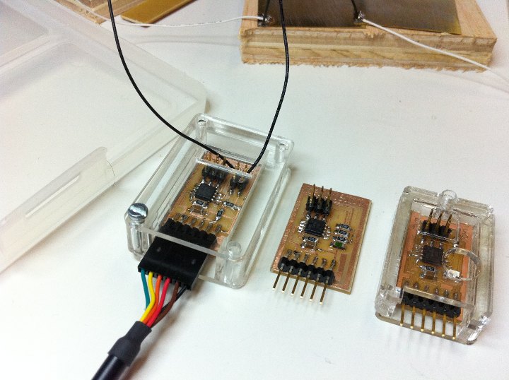
And eventually here is our small spaceship flotilla: hello.txrx.45, hello.light.45 and hello.temp.45 all of them working! [The white cables that we initially connected to the ground pins are not used]
[Comments]
In this page i have presented the three boards that we were able to make during the week as a collaboration between Jose Buzon, Juan Carlos Perez Juidias and myself. Each of us made one of the boards, mine being the hello.tempo one. The assignment is therefore complete.
[files download]
Unless otherwise stated, information and files in this page are downloadable under a Creative Commons Attribution-Share A Like license; attribution: Jose Perez de Lama / Fab Lab Sevilla / Fab Academy 2013

The files used in this class are Neil Gershenfeld's files that can be downloaded in the class web page:
http://academy.cba.mit.edu/classes/input_devices/index.html
My own files are the fab modules generated dxf initial path files, Rhino drawings of the ATtiny45V microcontroller and modified milling paths, and the .ai files used to import the modified paths into the iModela.
# ATtiny45 geometry [.3dm]
# fab modules dxf hello.txrx.45 mlling path file [.dxf]
# fab modules dxf hello.temp.45 milling path file [.dxf]
# Rhino 4 SR9 hello.txrx.45 paths [.3dm]
# Rhino 4 SR9 hello.temp.45 paths [.3dm]
# iModela hello.txrx.45 paths [.ai]
# iModela hello.temp.45.paths [.ai]
Software:: Fab Modules, Rhino 4 SR9, iModela C/C, hello.input.c, Python...
Hardware:: Roland iModela; hello.txrx.45 board; hello.temp.45 board; hello.light.45; Avrisp2
Materials:: FR1 boards, electronic smd components: see tables above
previous class:: 09 cc machining / next class:: 11 composites
return home /perezdelama.jose