Fab Lab Barcelona SuperNode /Fab Lab Sevilla /Jose Perez de Lama
Week 09 / computer-controlled machining / 20.03.2013
[assigment]
Make something "big" [using a CC milling machine]
Class syllabus:
http://academy.cba.mit.edu/classes/computer_machining/index.html
[assignment development]
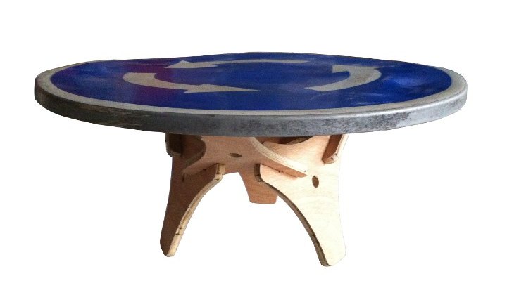
Last Christmas, once i had decided to take the Fab Academy, i found i an trash-container a discarded traffic sign, and decided to take it home, and maybe turn it into a small table, making some legs in the Fab Lab. I took some time then to sketch them in Rhino, again applying the polyhedra classes by professor Antonio Saseta, and checking out a design by former students Borja Baños and Belen Barrigon, which was based again on a workshop that we had in Sevilla in 2009 with Jeroen van Ameijde, the director of the Prototyping Lab at AA in London.
[design and cutting files]
Albeit so many previous references, the design is quite simple, but i think quite nice; and susceptible of multiple variations: modifying the size without further changes, modifying the relative length of any of the sets of pieces, or the design of the pieces maintaining the cut-out angles. Another way to evolve the design would be to substitute the regular tetrahedron for other pyramids, or for other polyhedra.
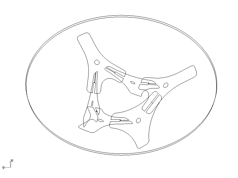
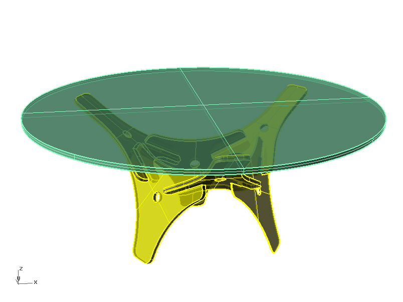
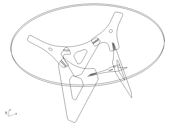
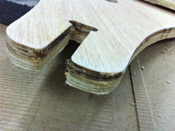
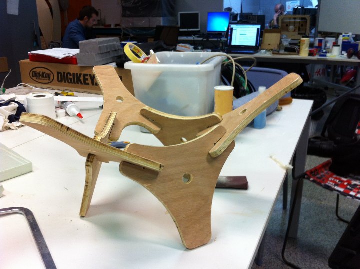
The design is indeed based on the geometry of a regular tetrahedron, using the faces [planes/angles] for one set of pieces, and the planes perpendicular to the edges, for a second set of pieces. Both sets are press fit together, making respectively the actual legs - set 01 -, and the supports for the top of the table - set 02 -, as can be seen in the images.
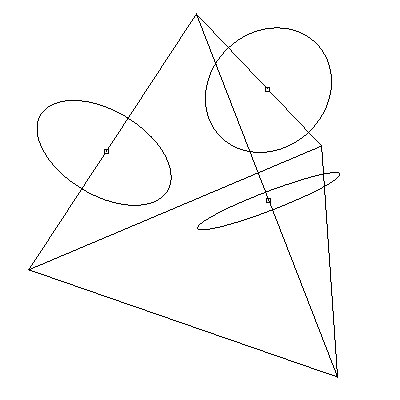
Basic initial geometry
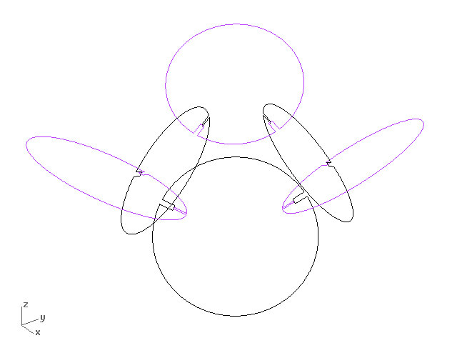
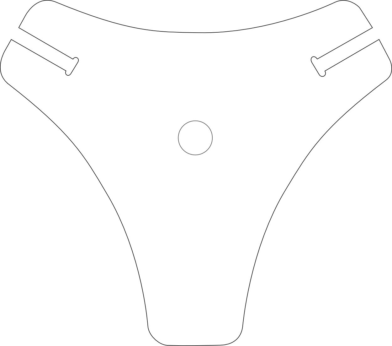
Cutting files: modules and machine layout. The cutting files have been prepared to be milled in 12mm plywood.
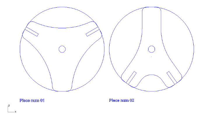
The design is composed by two modules, each of them repeated three times. Both of them are inscribed in a circunference, and have specific cut-out angles derived from the geometry of the regular tetrahedron. Not shown in the images above the necessary "ears" to cut them with the milling machine and recommended mounting chamfers that were later incorporated. The perimeter shape and circular cut-out in the center are placed for visual issues, that include makeing the table look lighter. The shape of the perimeter can be modified to achieve different design effects [see below].
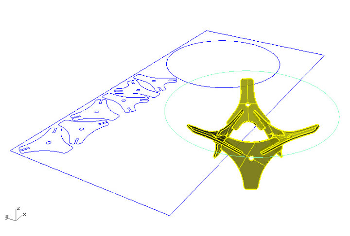
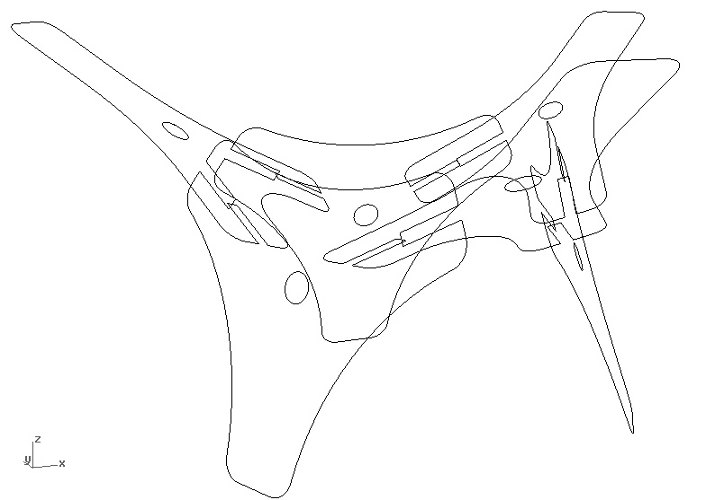
Cutting files [for a larger sized piece] placed in a 2400*1200 mm sheet + 3Dmodel. Below, actual project cutting file on the 2400*1200mm bed; with dotted lined the recycled piece that was actually used for milling:
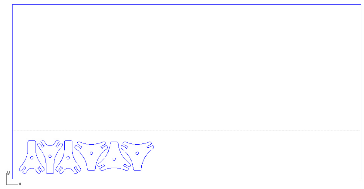
Below, a design variation with "longer legs".
[cc milling]
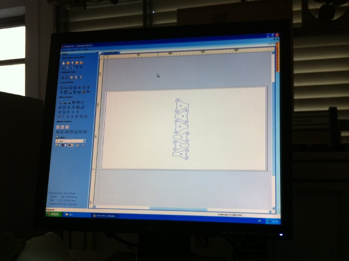
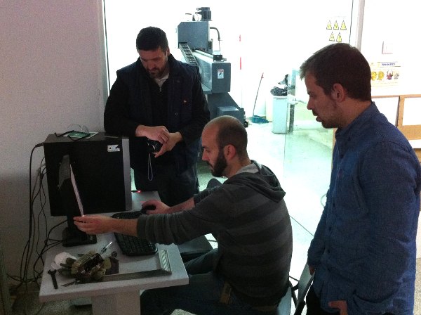
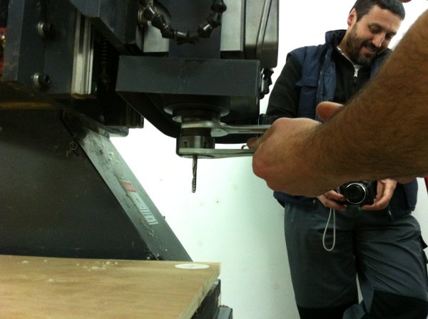
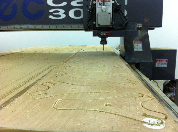
To mill the pieces we used a large [2500 x 1250mm] milling machine we have in the lab, the brand and model of which is TEC-CAM 3130. The software that we used is VCarve Pro 4.602, a rather oldish piece from 2008. It has a GUI similar to that of the Modela.
To importe the file in VCarve we converted the cutting file into a dxf using Rhinoceros. We arranged the pieces and the 0,0 position according to the left-out piece of plywood that we were going to use and how it would be placed in the milling machine bed.
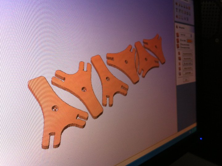
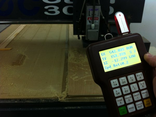
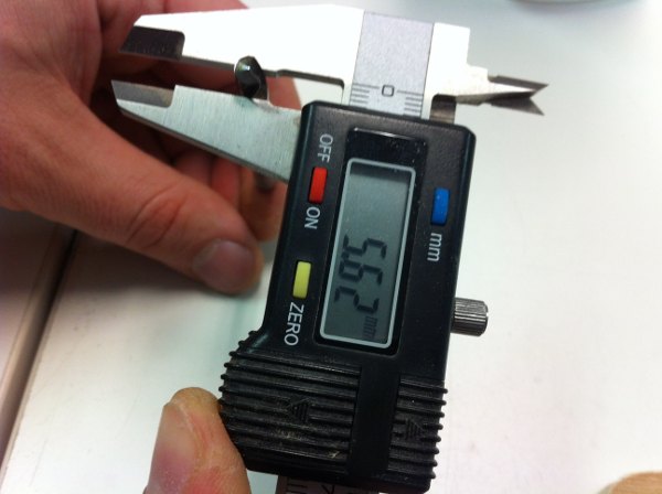
To configure the cutting process we set it up to mill with a 6mm end mill, to cut a total depth of 12.3mm [12mm plywood sheet that we measured to confirm with a caliper]. We set of cutting depth of 8mm for each level, that would cut the pieces in in two times; xy speed 0 3.000 mm/min; z speed = 1.000 mm/min. The speed can still be modulated once the cutting process is under way using the machine hardware. Using VCarve we designed some bridges to keep the small pieces in place while being cut; we gave them 5 mm width and 1.5 mm height. The software simulates the cutting process and we checked it to see if everything looked ok.
Eventually, we exported the file to the machine format, which is Mach2/3 Arcs (mm) that generates a txt file [see the dowloadable files at the end of the page]. This file we put in a pen drive that needs to be inserted in the machine control unit.
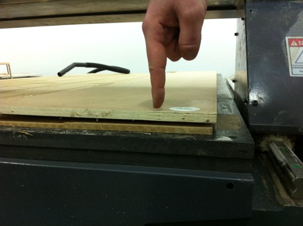
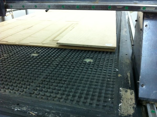
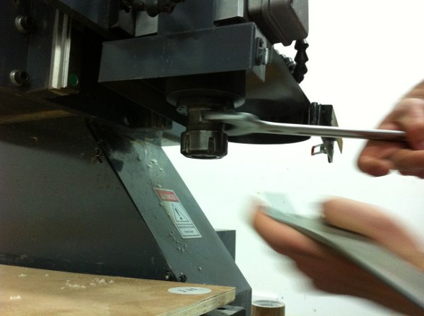
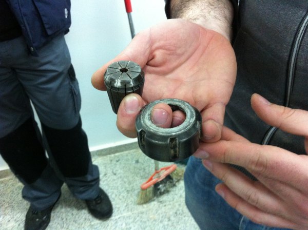
Then we prepared the board to mill. The milling machine has an aspiration system that is able to keep large pieces in place without fixtures or glueing. However, as the board wasn't completely flat we covered its perimeter with tape, as can be seen in the images, to allow for a better aspiration. We decided to try a new end mill that hadn't been tried yet. So we changed it, and set the zero, in xy and then in z. The process is similar to that of the Modela; just it is a bit more complicated to change and fix the mill. And then we started milling.
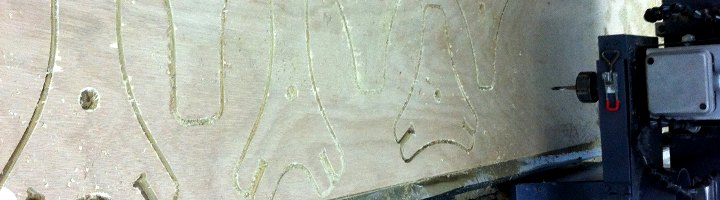
Milling quality was not very high quality. We realized the aspiration system wasn't very efficient in the parts of the board that were bended. And the cutting was not very clean. WE realized too, that some pieces were very close to burning - milling speed had bee too slow... The milling process was short, around 20 minutes.
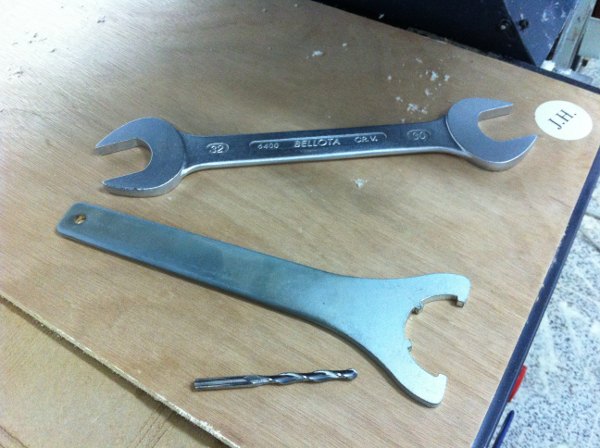
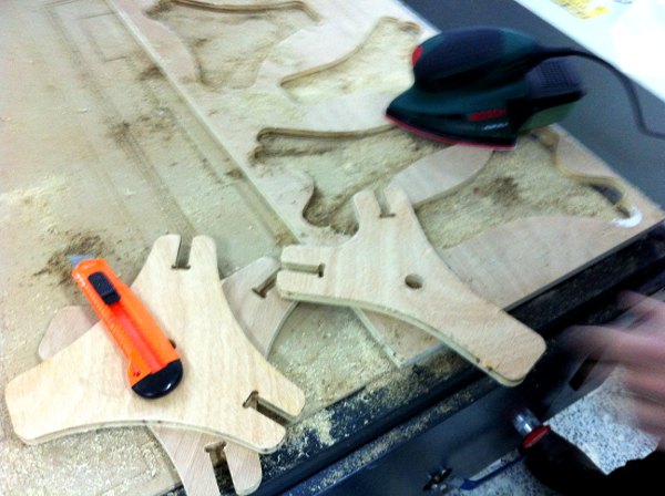
We did some sanding before lifting the pieces from the machine,- and i think that was a good idea, and then we finished the sanding job with an automated small sanding machine, and manually for the cut-outs. Then i realized the press fit was way to tight and a lot of sanding was needed to make the pieces fit. We checked the drawings and double checked the plywood height and they were right. Eventually we measured the not before tested end mill and it happened to have a diameter smaller than 6mm... So i had to spend some mor time sanding, until eventually the pieces were made to fit, and i could put the shape together. I have to say it looks nice. The next day i brought the traffic sign to the lab. I realized it is rather dented... I had used it as a low table on top of some amazon boxes. Now i will substitute the cardboard boxes for the fabbed stand. This is the place for the cable modem at home.
Postproduction and "material debugging":
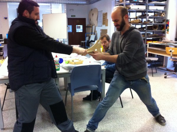
And this became eventually the provisional result:

[fab modules]
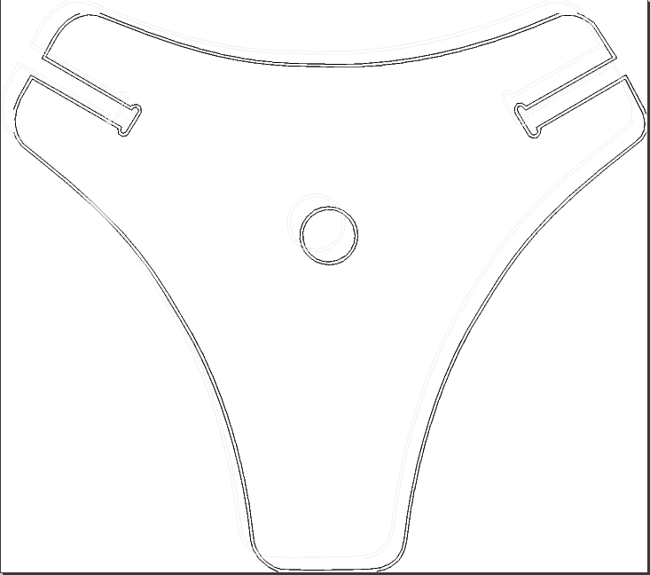
Having some days left this week i used an afternoon to test the fab svg-png to shopbot modules. I made an svg drawing of one of the pieces, using inkscape. Even if i like inkscape quite a lot i don't feel too comfortable with it making precise drawings. Nevertheless i produced a copy of one of the pieces and exported it as an inkscape-svg, plain svg and png. I also tried with a simple square with several variations on the way it was drawn: lines, full white surface over black background as with the png pcbs to rml.
This is the main piece i used for testing:
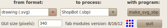
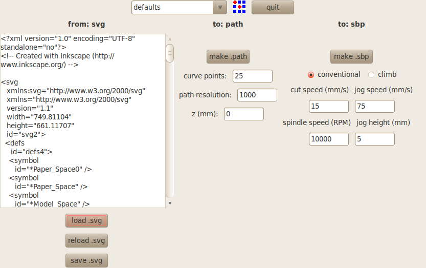
I began with the "svg-to-sbp" module. The svg i could not import into fab modules, however. I tried various formats and ways of drawing the piece but could not find any that worked. The message that i got was something of this sort:
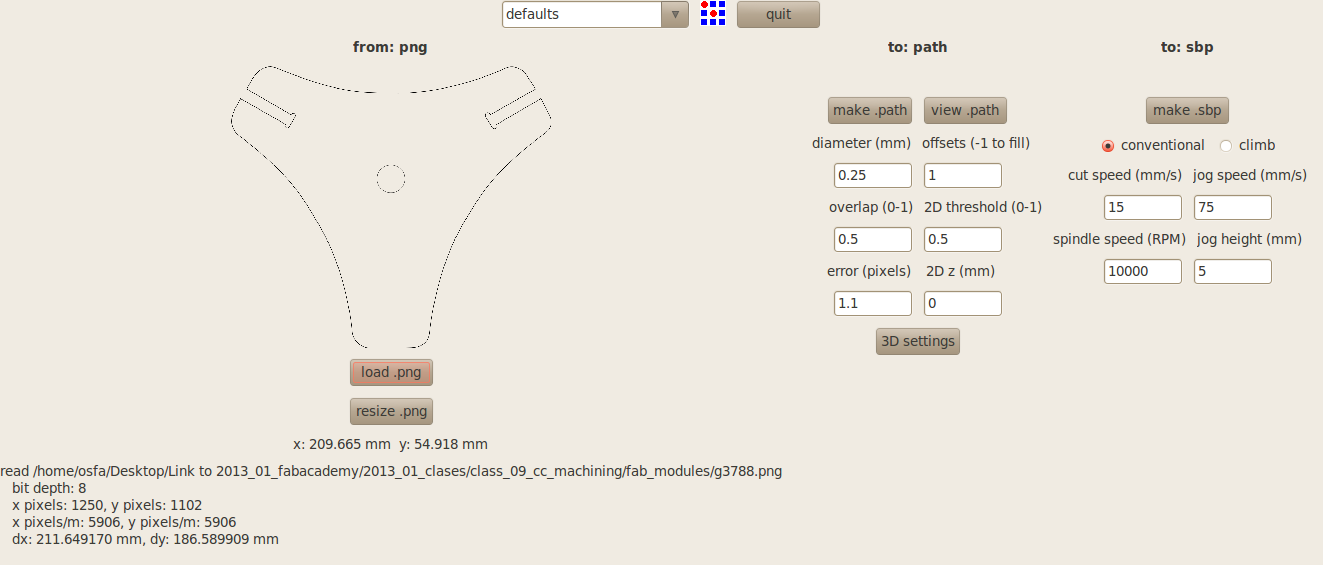
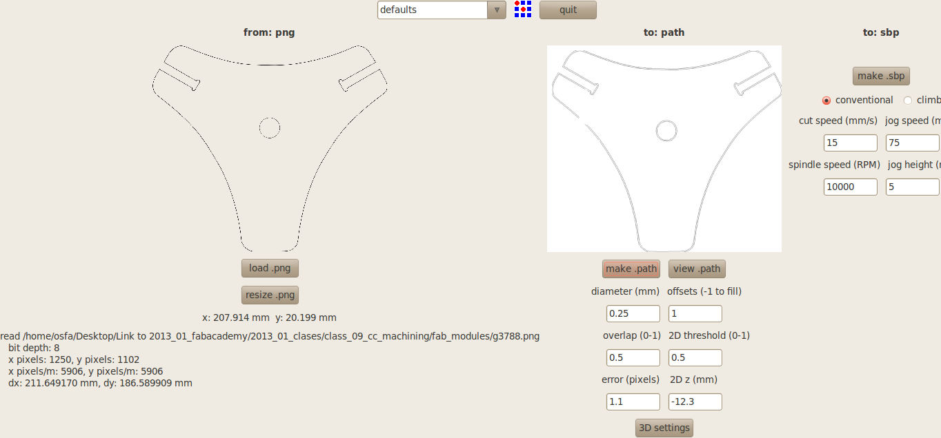
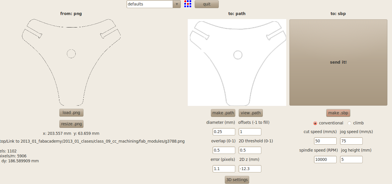
So i moved on to test it exporting the drawing as a png. Dimensions might be a bit tricky, but it worked pretty well.
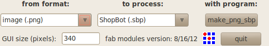
First you import the png, then you make a path; next to fine tune the parameters. In my case i tested the same ones that i had used in my earlier fabrication process: 6mm end-mill diameter, -12.30mm total depth cut, -8mm for each step. I still don't know too well what the top and botton intensities mean. I tried 1 and 0.5 for both and didn't realize any difference. Here you have to set some of the parameters in the 3D settings opo up menu.
You can check the path in detail using the chaeck path button that open an Okular window. Eventually you can generate the spb file. The files are stored in whatever folder you were when you called fab from the terminal. In my case it was home.
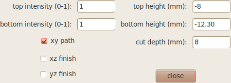 3D settings menu
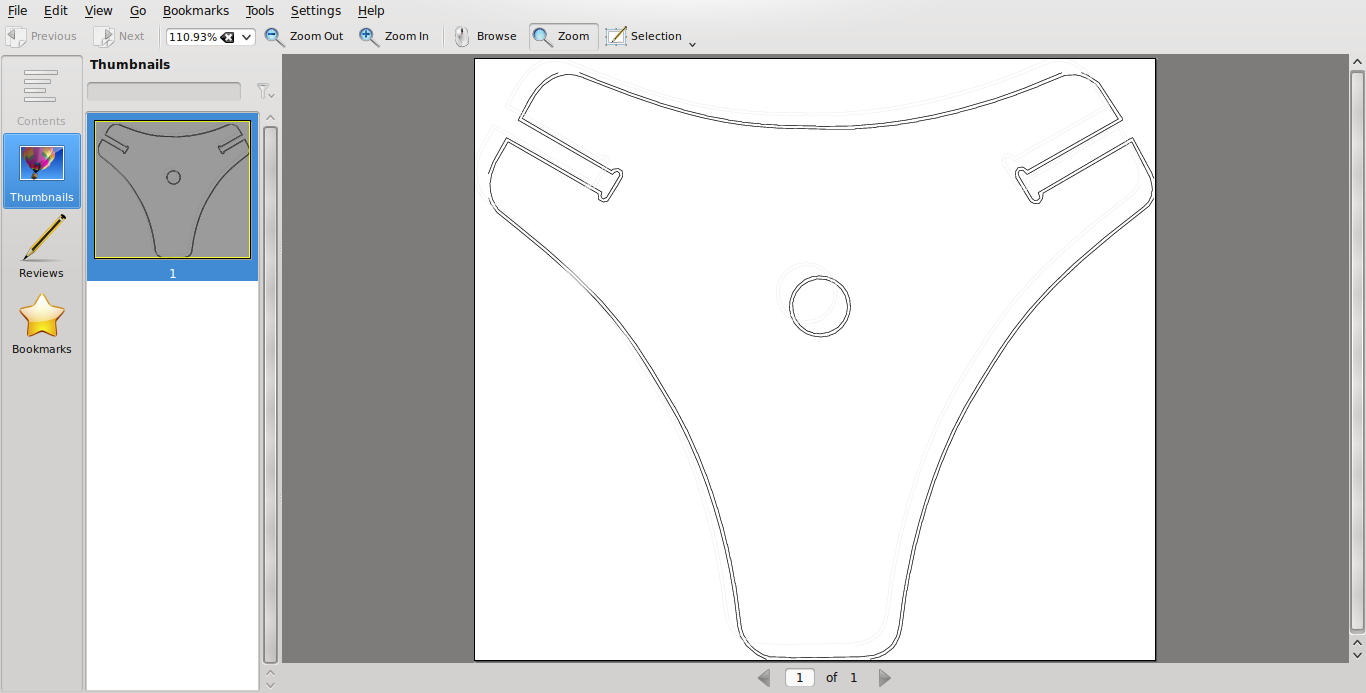
The process generates two files, with extensions .path and .sbp [shopbot], than can be opened with a text editor like gedit [attached at the bottom of the web page].
The path file is a geometric description of the paths, while the sbp is the machine file, that includes the geometry + plus various machine orders such as speed, motors on-off...
The sbp file looks like this:
SA
TR,10000,1
SO,1,1
pause,2
MS,1.968504,1.968504
JS,2.952756,2.952756
JZ,0.196850
J2,4.109615,4.770602
M3,4.109615,4.770602,-0.314961
M3,4.096272,4.763929,-0.314961
M3,4.009543,4.737241,-0.314961
[...]
M3,1.107461,7.319371,-0.484252
M3,0.980704,7.332715,-0.484252
MZ,0.196850
J2,3.482498,0.006672
M3,3.482498,0.006672,-0.484252
M3,3.455813,0.020017,-0.484252
M3,3.362412,0.066722,-0.484252
M3,3.228983,0.180149,-0.484252
[...]
M3,0.793903,7.319371,-0.484252
M3,0.867289,7.346059,-0.484252
M3,0.873960,7.352731,-0.484252
MZ,0.196850
My z milling coordinates were -8mm and -12.30 mm which seem to be equivalent in machine coordinates to -0.314961 and -0.484252. These are the same coordinates translated into inches [decimal].
This done i went back to the svgs. I checked the messages in the terminal, and realized it said there was a problem with open segments. Then i made a new simple drawing in inkscape using only lines and closing them making a rectangle. This did work and generated a simple but good looking sbp file [with no depth, because i hadn't given any]:
SA
TR,10000,1
SO,1,1
pause,2
MS,0.590551,0.590551
JS,2.952756,2.952756
JZ,0.196850
J2,1.828994,6.868449
M3,1.828994,6.868449,0.000000
M3,1.828994,6.868449,0.000000
M3,1.754510,1.845378,0.000000
M3,6.703554,1.845378,0.000000
M3,6.703554,6.868449,0.000000
M3,1.828994,6.868449,0.000000
MZ,0.196850
Re-reading this file, and comparing it to the former, it can be deduced that TR is the spindle speed = 10000 rpm;
MS seems to be speed in x and y, here 15 mm/s, probably translated into inches;
JS seems to be some kind of x,y zeroing, even if it is somehow in the middle of the square.
And JZ the jog height,
all of which, but JS, the parameters introduced in fab modules when generating the sbp file.
J2 seems to mark the "pen-up" movement;
M3, the "pen-down" movement;
MZ, motor stopped.
[files download]
Unless otherwise stated, information and files in this page are downloadable under a Creative Commons Attribution-Share A Like license; attribution: Jose Perez de Lama & Fab Lab Sevilla / Fab Academy 2013

# Tetrahedron press-fit table Rhinoceros file [.3dm]
# Tetrahedron press-fit tablestand dxf cutting file [.dxf]
# Tetrahedron press-fit table stand cam files [VCarve.txt]
# Tetrahedron-table module fab modules generated .path file [.path]
# Tetrahedron-table module fab modules generated shopbot file [.sbp]
Software:: Rhinoceros 4 SR9, VCarve Pro 4.602; tested fab modules svg-png-to-sbp
Hardware:: Tec-Cam 3130; 6mm end mill; handheld automatic sanding machine; sanding paper
Materials:: 15mm 2400*1200 mm plywood; recycled traffic sign
previous class:: 08 embedded programming / next class:: 10 input devices
return home /perezdelama.jose