March 2013
Electronics Design / 3D Scanning and Printing / Moulding and Casting / Computer Controlled Machining
Moving on from the first circuit board to the second (have given up trying to get past Massey's proxy servers with our scanning and printing using 123d Catch...grrr).
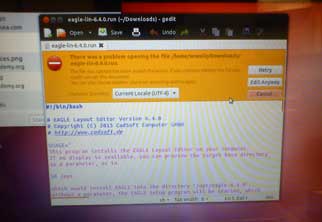
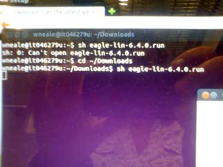
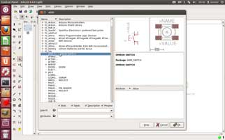
Downloaded Eagle - a couple of problems working out how to install it on Ubuntu, but once again Bas points out a ridiculously small thing I'd overlooked. In my defence, I suspected that 'shell' meant 'terminal' but I didn't think it for long enough. The interface with Ubuntu is becoming clearer. We were trying to work out how to get the computer to recognise the Vinyl cutter today, and I actually understood what we needed to do to the commands to get to where the tutorial was telling us we needed to go to. Not that it means that we fixed it. We still can't print anything on the Vinyl cutter using Fab Modules. Yet. Though with Bas's help last night I got my laptop to recognise the Vinyl cutter, so we might be in luck when I move on to the Lab computer - try dmesg using a different USB port. Fingers crossed.
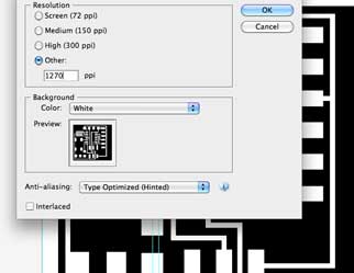
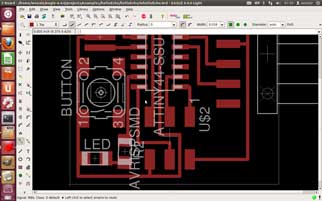
Used the layout from the first circuit to help me work out what I needed for the second circuit. We added a light and a switch to this, using Illustrator, as Eagle is completely incomprehensible to me. I took the original PNG into Illustrator, locked it, and worked out all the sizes of pads and lines that I needed to make and then drew them on top. Exporting it from Illustrator back to PNG requires some pretty high dpi, as you can see below, otherwise it pixelates too much and the tolerances for machining change. It was a little tricky for both of us to work out how to connect everything (ground and diodal direction - I made that word up - being the biggest issue), given our lack of electrical knowledge, but we did it.
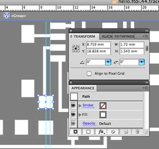
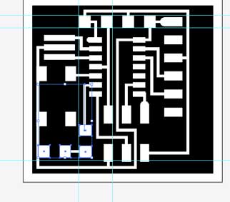
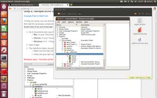
One day that will change ...I hope. You can find these files here. You will see below that the light works! Had a go with following Anna's Eagle tutorial, and things are going well so far...
Bas has also worked out what I did wrong with the first circuit board so that's good to know. It was a difficult thing to troubleshoot from a distance. Hopefully I avoid that in the next one....
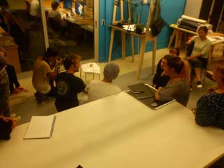
Back to the scanning and printing: Stuart and I set up a random pattern on our tabletop and made sure we had good lighting and took a whole lot of photos of our objects - a sample photo below. You will see that we also involved the students who were interested in using 123d Catch. The eggcup was originally shiny, so a matte finish was applied before photographing. As mentioned previously, had some problems with our proxy servers at Massey, so we also scanned our objects using the fixed scanner that we have.
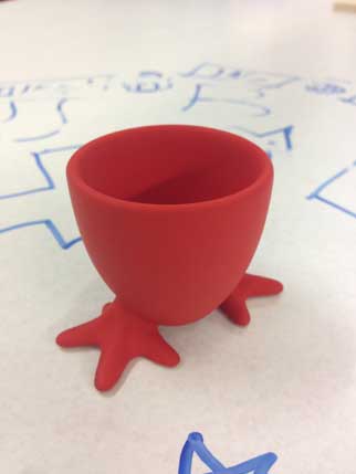
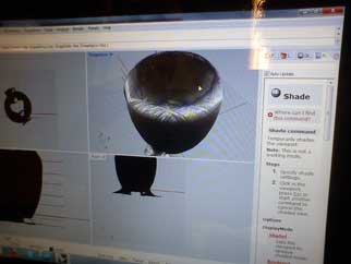
The.stl that came out of the scanner was a little dodgy.... so I had a play in Rhino until I got it looking better.... Quite a steep learning curve there - you can see below one of my more amusing attempts at fixing my meshes.
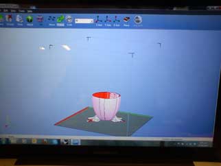
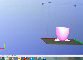
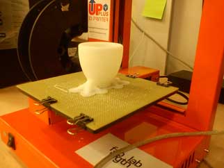
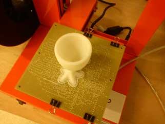
Success was sweet and I was able to print it out on the Up Printer, using ABS because I was super-confident that it would be perfect first time. And it almost was: a slight slippage in the cup between the feet where the curve possibly needed a little support structure in the build. The files for this are here.
Moulding and Casting
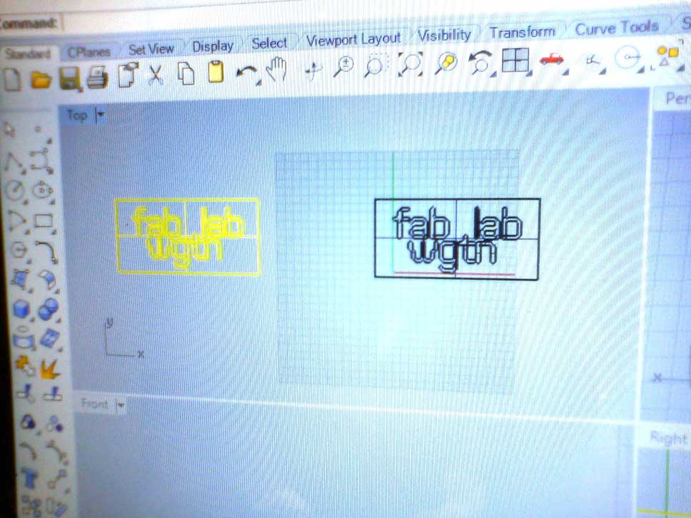
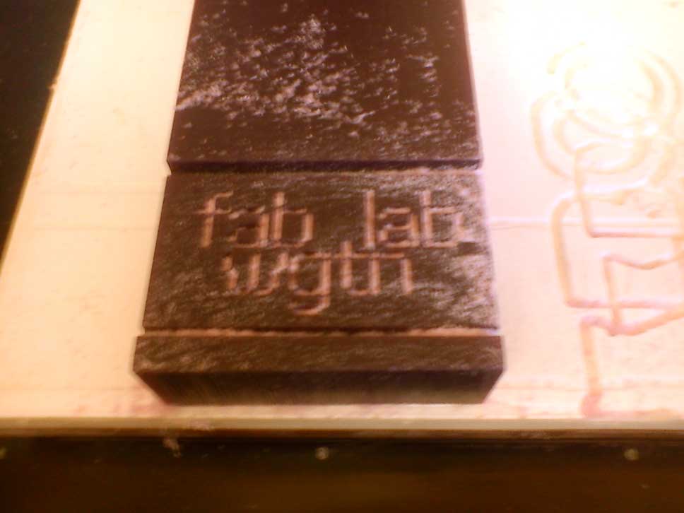
LOVE LOVE LOVE machineable wax. I thought about splitting my eggcup and moulding that but decided to go back to the idea of a fab lab wgtn stamp, which I've already made on the laser cutter. A few weeks ago you'll remember I had a crack at TinkerCAD, and I wish I could tell you I persisted and made an .stl using that... but I didn't. I consolidated my Rhino learning by generating it in that.
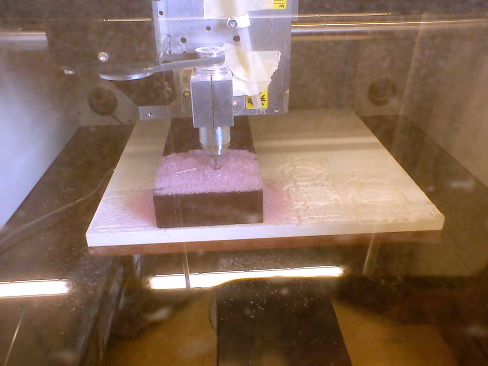
Once I'd made that and exported it, I went to print it out on our MDX40a, and then remembered that in reconfiguring all our computers it wasn't set up. So, in the midst of all the students wanting to chat, learn how to laser cut/3D print/learn Partworks and one student wanting to print out a circuit board on our mini-modela, I downloaded and installed all the windows-based software I needed and by the end of the day, got the Modela cranking out my wax mould. I hot-glued it in place. It worked. I thought I'd have to lasercut a frame for the wax to sit in, and while that'd still be an option, I'm pretty happy with the hot glue when I'm doing a small job on a big piece with a small cutter. I'm sure you'll let me know if you think that's dangerous.
I've got the wax shavings in a bucket, ready to re-form and re-use. That's why I love the wax - I've decided to keep that machine only for wax, as we have another one elsewhere that we can use for dust producing materials. Everyone else I've talked to about this thinks it's a good idea, and some are really keen to use the wax as well - another exciting outcome from Fab Academy.
I found some flexible urethane and some oomoo in the back of our cupboard (50ml in a 250ml container), so I've used these to roll out the first ones in the hopes that it will clean up any last bit of dust in the mould. I'll be very keen to see how the fresh oomoo works with fine detail, as I'd usually use some other products that are excellent and more readily available in New Zealand. These tests aren't really an indication of whether my detail is too fine for the product as they are using product that is beyond its use-by date.
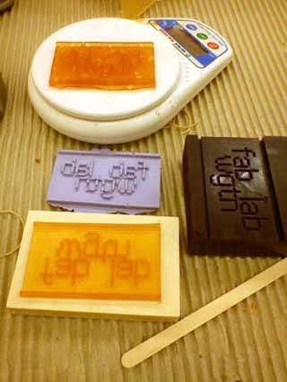
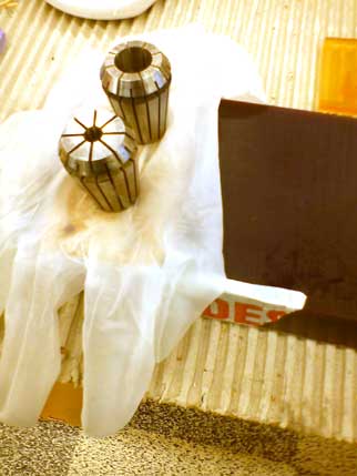
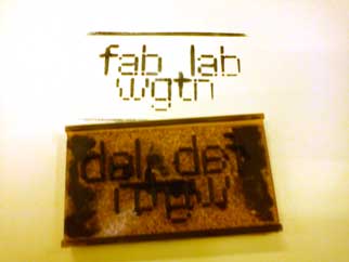
So, the final stamp is above right. I drilled some holes in reconstituted corkboard (weighed it down with some handy shopBot collets so it wouldn't float) and cast around it so that there would be some substance behind the flexible rubber. I'm pretty happy with the results. I can stamp everything now!
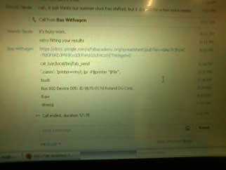
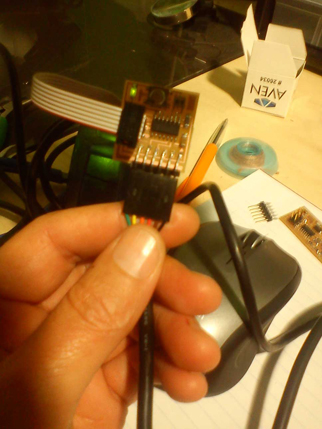
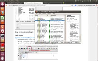
And... in other awesome news.... drumroll please: My third attempt at making my programmable circuit board has worked. There is actually something wrong with one of the usb ports on my laptop when it's in windows. But look what message I got when I finished programming it in ubuntu - just as Anna's tutorial says:
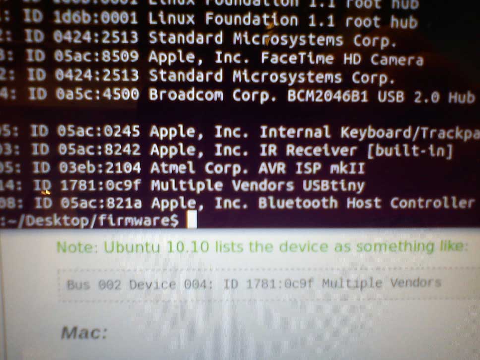
And then I plugged it in to another windows computer, and the computer recognised it was a usb. Yay. A moment of bathing in the glory before I launch into the next bit.
Make something BIG - Computer Controlled Machining
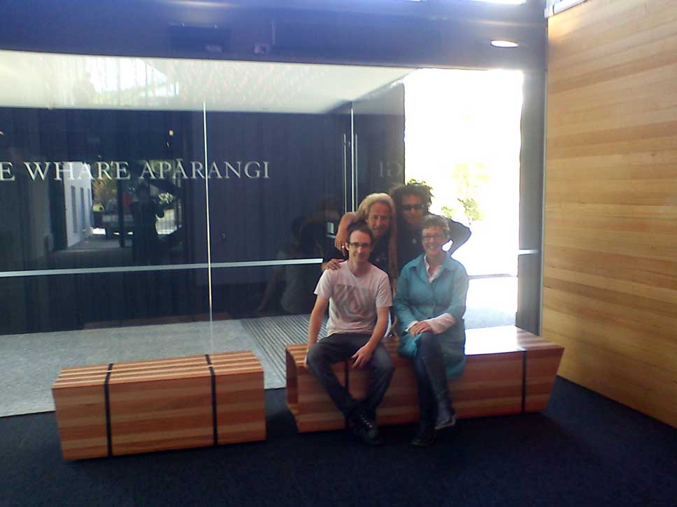
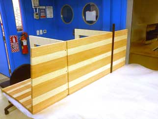
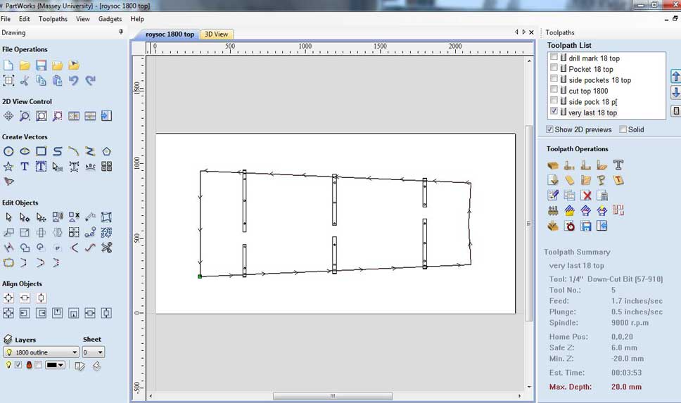
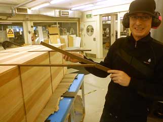
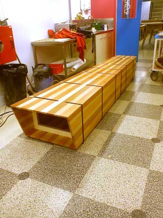
Stuart and I worked on a project after Fab8, where we designed and made a couple of large seats for the Royal Society of New Zealand using timber that had been developed by a scientific research facility called Scion. While we didn't develop the design specifically for the shopBot, it ended up that it was the best way to make it at the time.
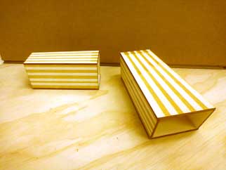
It was an interesting process... after doing some sketching and development, which included a couple of laser maquettes and full scale mock-ups, and a few consultations with the staff of the RSNZ, I developed the idea further in Illustrator. It was a very layered file - it would have been more practical to do it in Rhino as a 3D object, but I didn't know how to do that, so Illustrator it was.
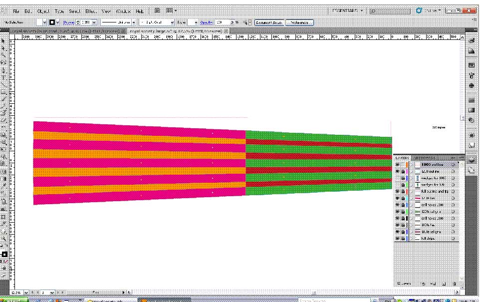
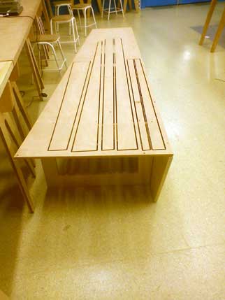
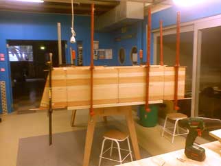
I used the final position of the screws to secure the wood to the shopBot bed when machining the taper on all the pieces for the tops and bottoms, after which we glued the tops and bottoms together, then machined the final shape with the grooves for the inlay timber.
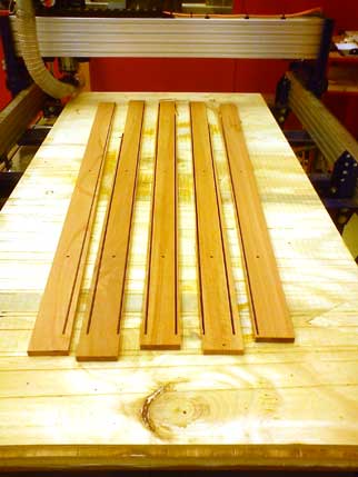
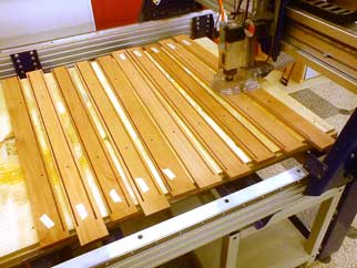
This was all quite a complex process, but allowed for a higher level of precision than was achievable using a jig, the table saw and the thicknesser.
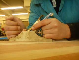 Though we still did some hand-finishing. With my lovely No. 2 Lie-Neilson. Which I love.
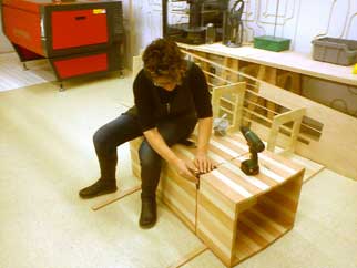
The delivery team...good times with Eddie and Karl in a ute.