Programming
SAMD vs Arduino pin numbering
The actual pin numbering of samd21 chips (e.g. portA21 or portB30) is in no way related to arduino pin numbering used in sketches.
To get to the arduino pin number, see the variant.cpp file. In this file you’ll find the PinDescription table of this microcontroller.
Look for the actual pin number you want to program and check the commented line above it to find the arduino numbering. e.g.:
PORTA, 21 on line 130 -> // 12..Digital functions (line 120) -> meaning actual pin number PA21 = arduino number 21
PORTB, 30 on line 166 -> // 43..46 - SPI Header (line 165) -> meaning actual pin number PB30 = arduino number 43
Arduino equivalent: Arduino Zero, Adafruit feather M0
To make sure I can lookup interesting example code, it’s a good idea to check if there’s an Arduino equivalent of the microcontrollers that I’m using. I found the Arduino Zero, which uses the SAMD21G18 microcontroller. This is the 48-pin version of the SAMD21 series. I’m going to use the 32-pin (SAMD21E18A) and the 64-pin (SAMD21J18A). Codewise, they shouldn’t make a big difference. Also the adafruit Feather M0 has the same chip.
SAMD21J18A Microcontroller for sensor controller board
My sensor boards are equipped with SAMD21J18A 64 pin microcontrollers. They have 1 12-bit ADC that is connected to 20 input pins. I’m going to continuously measure 19 pressure sensors with one sensor board (which equals to 1 octave of my Marimbatron) and send the result over I2C bus to the main controller. I’m also using this microcontroller to send RGB color information to the 19 WS2812B RGB LEDs of each individual sensor.
analog input sampling (ADC)
Test
First loading the example that I made on the SAMD11C14:
#include <Adafruit_NeoPixel.h>
#define LEDPIN 43 // PB30 = arduino 43
#define STARTLEDDELAY 100
#define SENSORPIN 6 // AIN14 on PB6 = arduino 6
#define LOOPDELAY 10

#define NEOPIXELPIN 39 // PB10 = arduino 39
#define NUMPIXELS 1
Adafruit_NeoPixel pixels(NUMPIXELS, NEOPIXELPIN, NEO_GRB + NEO_KHZ800);

const unsigned long intervalSensor1 = 50;
const unsigned long intervalLED = 1000;
unsigned long previousTimeSensor1 = 0;
unsigned long previousTimeLED = 0;
bool ledStatus;
void setup() {
  pinMode(LEDPIN, OUTPUT); // set LED pin to output
  digitalWrite(LEDPIN, LOW); // turn LED off
  delay(STARTLEDDELAY); // wait
  Serial.begin(15200); // enable serial communication
  pinMode(SENSORPIN, INPUT); // set sensor pin to input.
  pixels.begin();
  pixels.clear();
  pixels.setBrightness(50); // Set BRIGHTNESS to about 1/5 (max = 255)
}

void loop() {
  int ADCMeasurement;
  unsigned long currentTime = millis();

  /* This is the event for sensor 1*/
  if (currentTime - previousTimeSensor1 >= intervalSensor1) {
    /* Event code */
    ADCMeasurement = analogRead(SENSORPIN);
    Serial.println((String)"Measurement value = " + ADCMeasurement);
    int pixelColor = map(ADCMeasurement, 900, 1023, 0, 65535); // map(value, fromLow, fromHigh, toLow, toHigh)
    int color = pixels.gamma32(pixels.ColorHSV(pixelColor)); // hue -> RGB
    pixels.setPixelColor(0, color); // Set pixel 'c' to value 'color'
    pixels.show(); // Update strip with new contents

   /* Update the timing for the next time around */
    previousTimeSensor1 = currentTime;
  }

  /* This is the event for sensor 2*/
  if (currentTime - previousTimeLED >= intervalLED) {
    /* Event code */
    digitalWrite(LEDPIN, ledStatus);
    ledStatus = !ledStatus;

   /* Update the timing for the next time around */
    previousTimeLED = currentTime;
  }

}
The firmware of the sensor module
V1 Read all sensors
Next is to do it in a less “arduino” way. Analogread works fine, but it also hides some of the advanced features that I might or might not need. From what I understood, the Analogread function also enables the ADC and disables it after every readout. I don’t think I want that (for speed purposes).
So diving deeper. good resources I’ve read regarding the ADC:
https://blog.thea.codes/understanding-the-sam-d21-clocks/
https://blog.thea.codes/reading-analog-values-with-the-samd-adc/
https://blog.thea.codes/getting-the-most-out-of-the-samd21-adc/
Atmel AT11481 application note on ADC configurations with examples
and of course the datasheet
From the above mentioned blog posts, the procedure to get the ADC to work is:
- Enable the bus clock to the ADC.
- Wire up a peripheral clock to the ADC.
- Load the ADC’s calibration values.
- Configure the measurement parameters.
- Configure the pin for the ADC function.
- Start the ADC and trigger a measurement.
Code that is required to do these steps are mentioned in the blogpost.
Important note to measuring using the ADC of the SAMD devices can be found in the datasheet and in the AT11481 application sheet linked above:
- Discard the first conversion result whenever there is a change in ADC configuration like voltage reference / ADC channel change
- When switching to a differential channel (with gain settings), the first conversion result may have a poor accuracy due to the required settling time for the automatic offset cancellation circuitry. It is better to discard the first sample result.
As I’m going to continuously change ADC channels (from 0 to 19), I’ll always have to “measure twice” and disregard the first measurement.
The ADC has the following block diagram (from the datasheet):
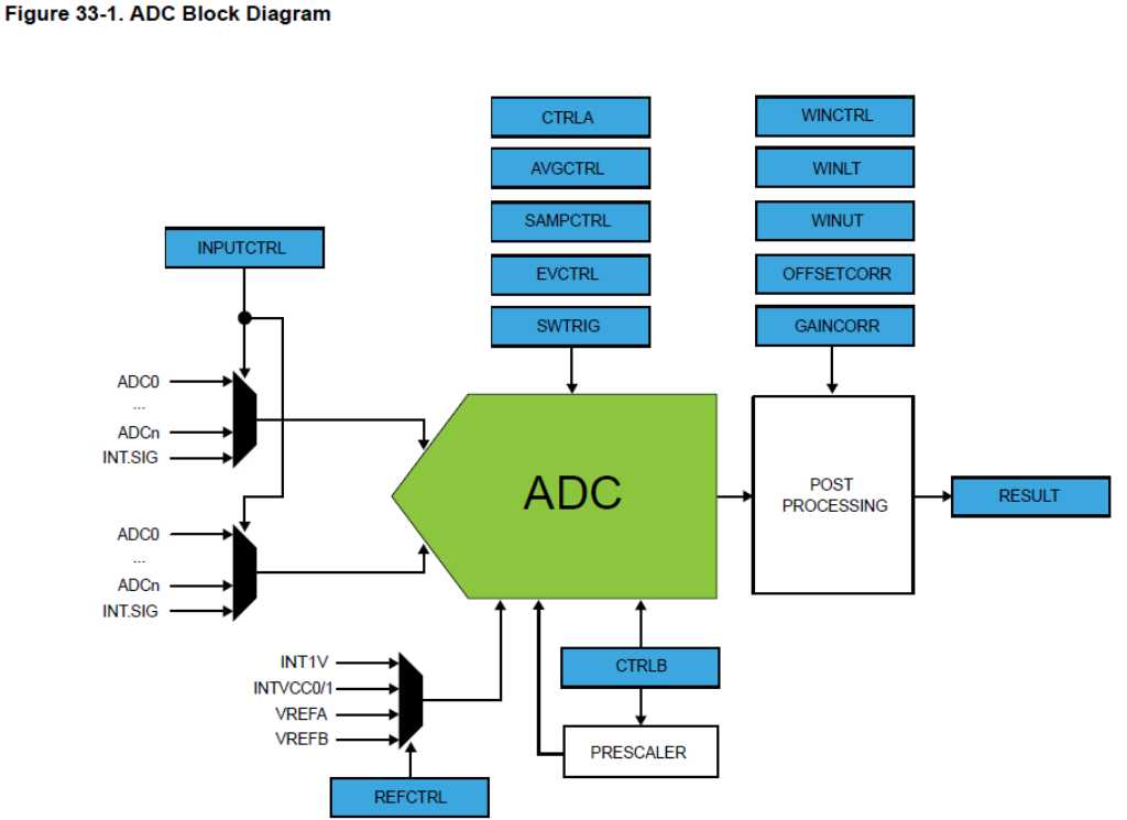
V1 of the firmware of the sensorboard has the above applied. What it does:
- blink the red and green leds
- drive 1 WS2812B RGB led and cycle the colorwheel
- read out 20 analog sensor inputs (12 bit ADC) and output their value in the serial monitor
Here is a screenshot of the serial monitor with 1 sensor attached to input 8. The ADC is set to 12 bit so the maximum value is 4095. Without the graphite sprayed PET circle (no conductance at all), the output varies between 4085 and 4095. With the PET circle and the top sensor part the output is around 3870 (this is because there is a bit of conductance due to the graphite and a bit of pressure due to the weight of the sensor top part).
When pressing, the measured value goes down into the 700’s.
Find the sketch (firmware V1) here in my final-project repo
V2 Hit detection
Now it’s time for hit detection.
Hit detection is usually done by using these variables:
- threshold
- scantime
- mask time
Great resources that I used (next to my knowledge of Roland drumtriggers) are these sites:
megadrum -> a drumtrigger that I own.
hellodrum arduino project -> an arduino library for drum triggers
This image that I took from the hellodrum project explains hit detection very well:
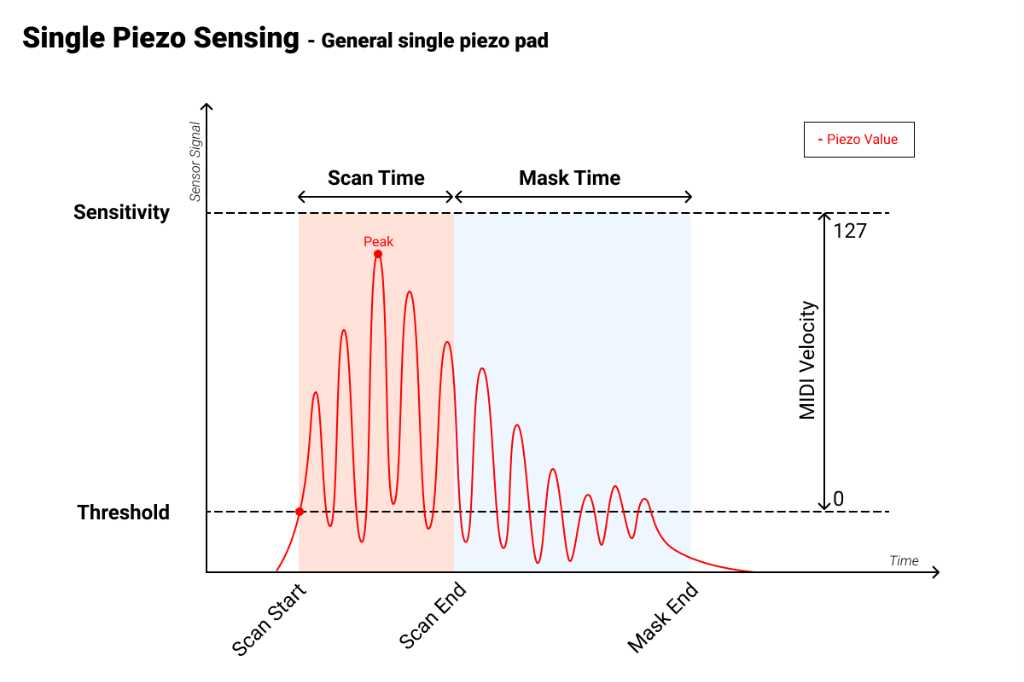
Although this is based on a piezo, my sensors will work similarly. With less highs and lows before and after the peak though. So sensing should even be easier.
The idea is that you measure in high speed (microsecond speed). As soon as the measured level is above the threshold level, the scan time begins. During this time, keep measuring and detect the peak level of the signal (local maximum, or in my case a local minimum as my sensor works inverted). As soon as you find the maximum peak level and scantime is over, you store the peak level. Next, the mask time begins. During this time you don’t measure anything. This is to prevent false triggering. Again, in my sensor the signal is much cleaner, but false triggering is no good anyway.
First I’m going to connect a pressure sensor to an oscilloscope and hit it. To see what measurement results I get.
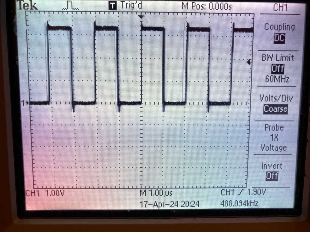
Here’s a hard hit on my sensor. Note that this signal is inverted because my sensors works that way (pressing harder = voltage goes lower).
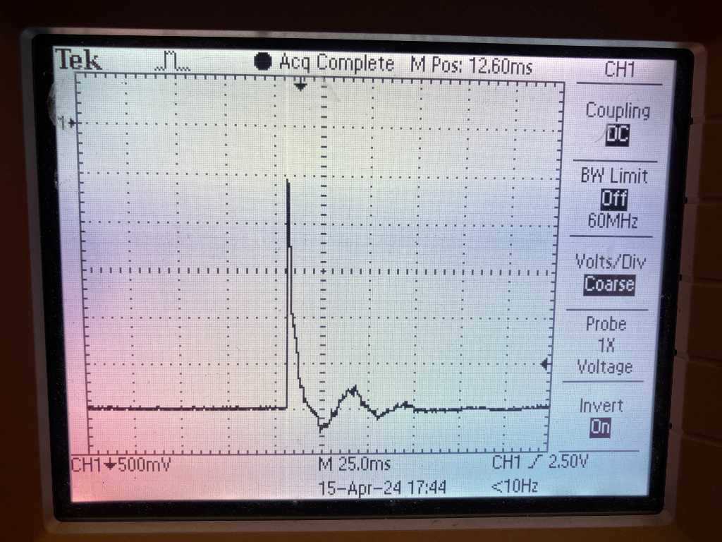
Same hit but zoomed in:
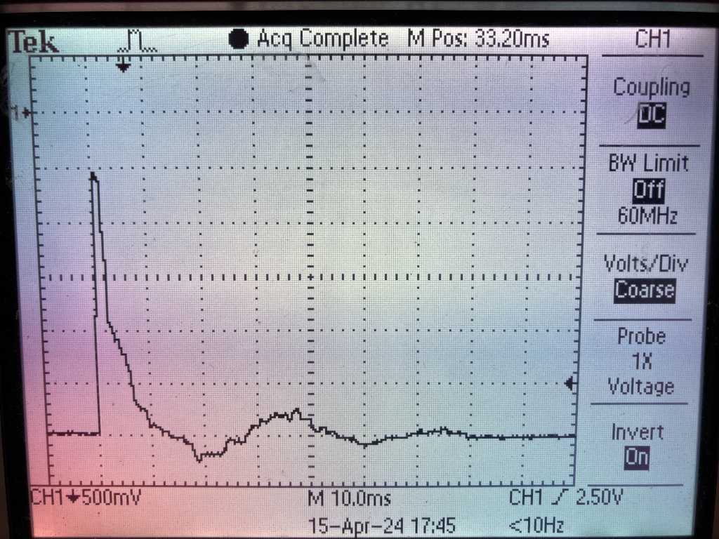
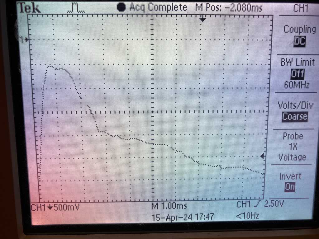
So the peak is at around 600uS after the hit. And a nice and clean signal.
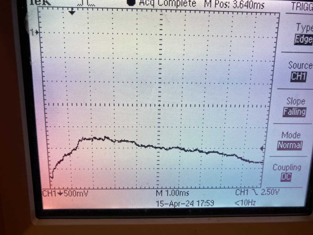
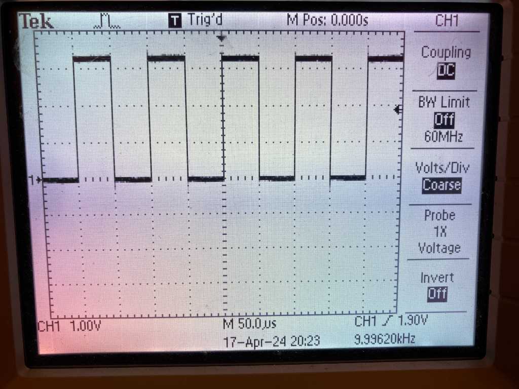
A very soft hit gets its peak after around 2ms.
A hard hit gets its peak after around 1ms:
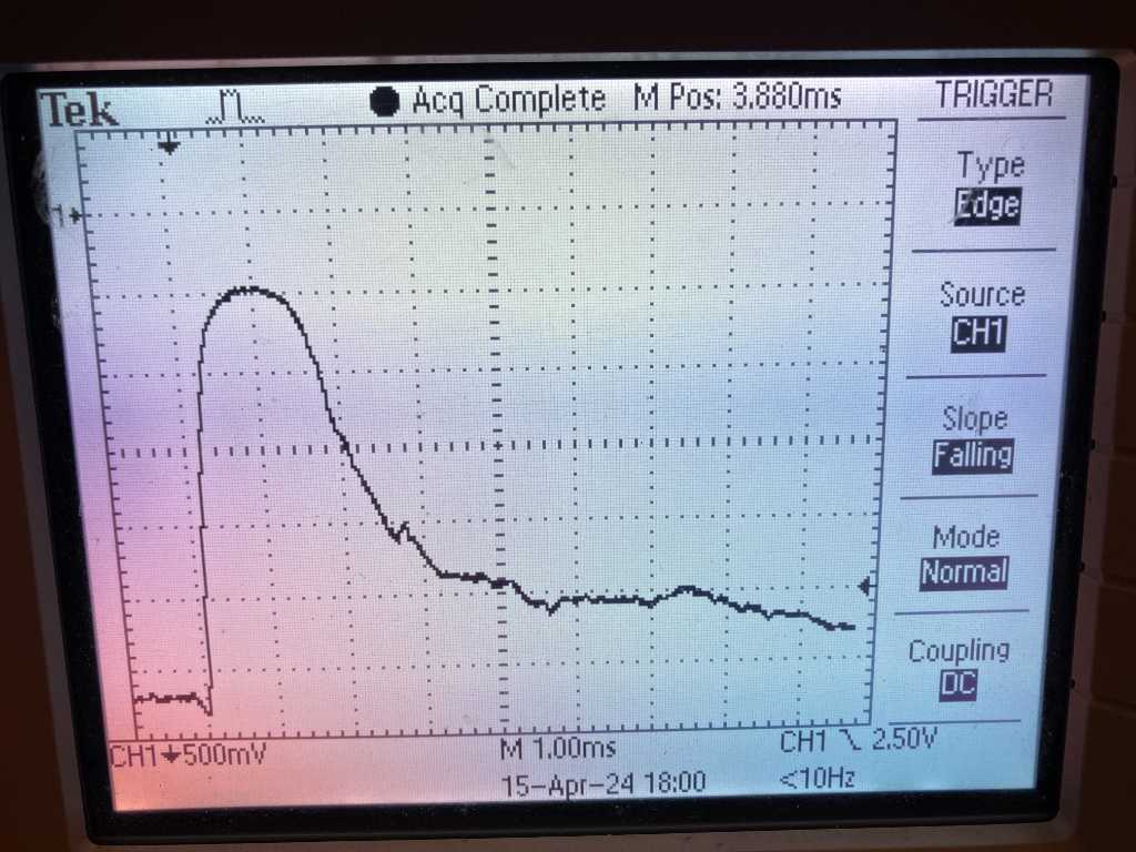
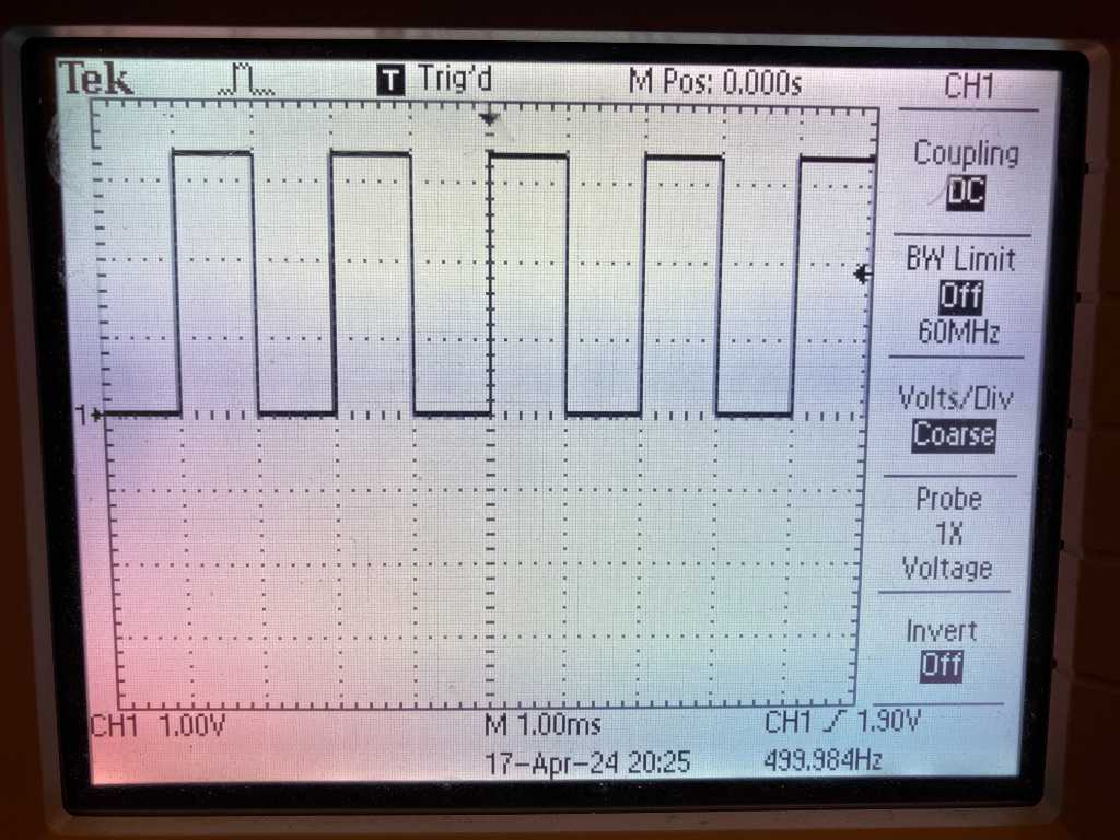
A very hard hit gets its peak after around 600uS:
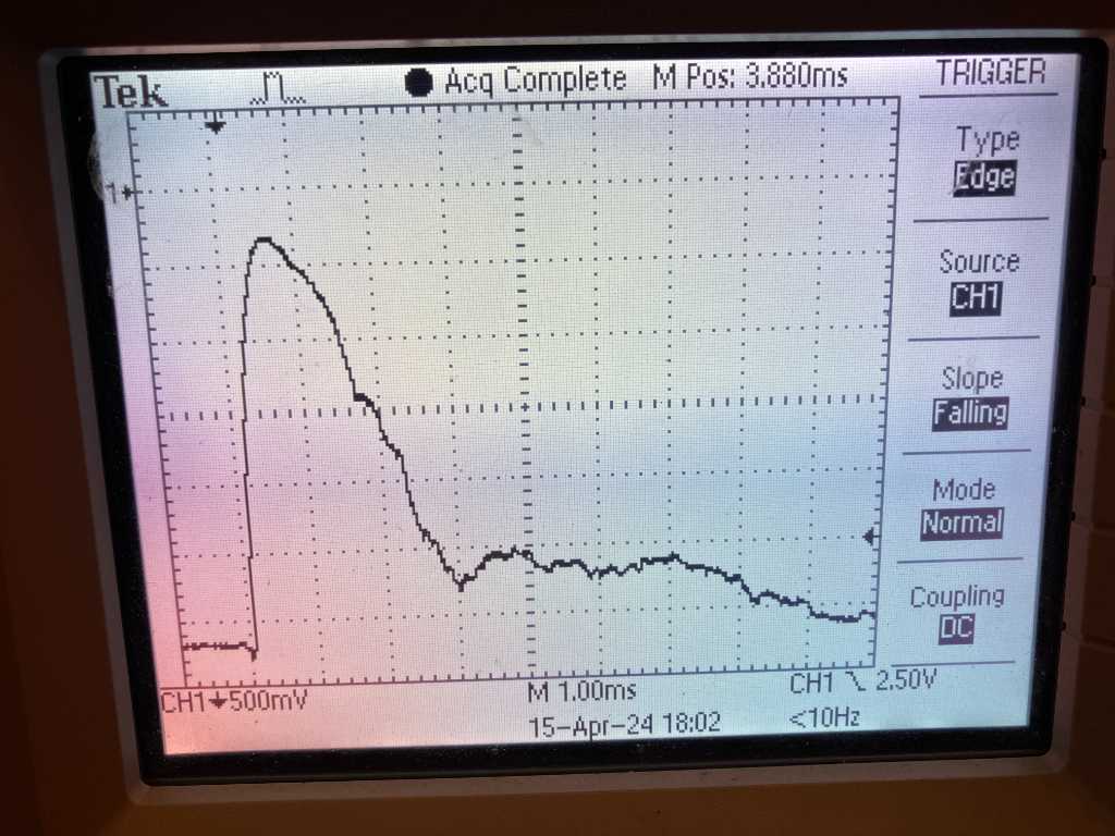
This basically means that any peak will be within 500uS and 2ms after it exceeds the threshold (trigger level on my osilloscope).
I also noticed that the voltage levels for medium to very hard hits are actually quite close to each other. About within 500mV. I think I will need to make some adjustments in software, e.g. by mapping the measured values to a curve instead of linearly go from measured value to MIDI velocity. this is very common to do by the way. All major e-drum manufacturers allow you to select a velocity curve.
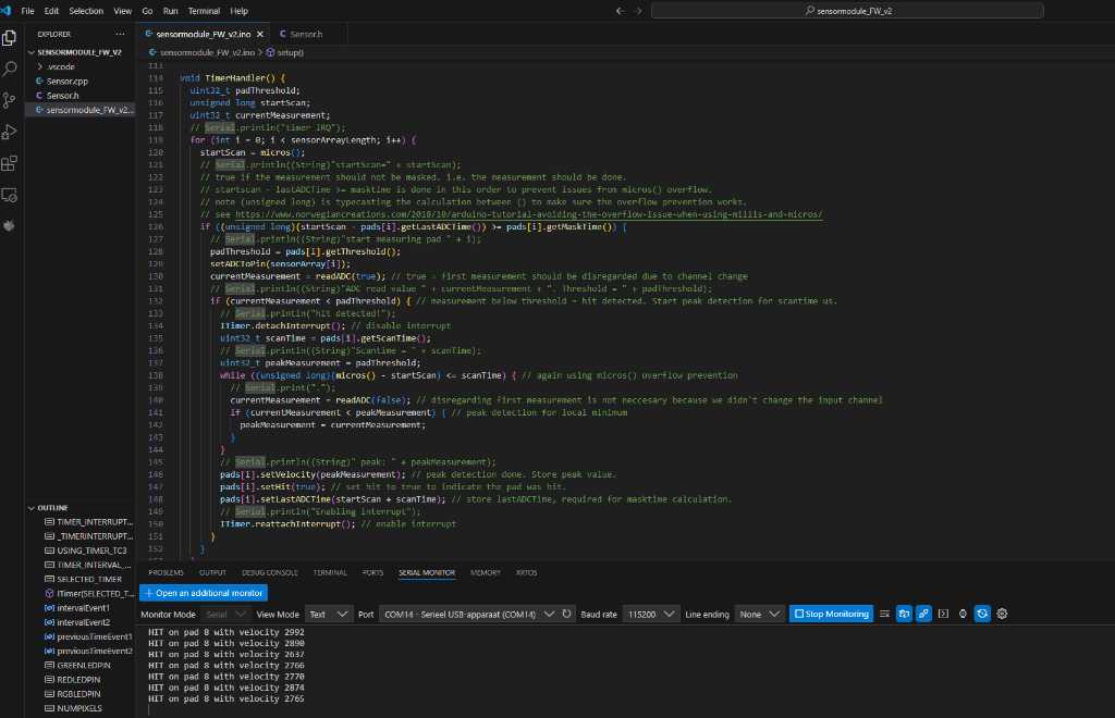
So I implemented this procedure in V2 firmware.
I implemented a timer interrupt service routine (ISR) so that on specific times all sensor inputs are going to be measured. In this ISR function, the threshold, scantime and masktimes are taken care of:
void TimerHandler() {
  uint32_t padThreshold;
  unsigned long startScan;
  uint32_t currentMeasurement;
  for (int i = 0; i < sensorArrayLength; i++) {
    startScan = micros();
    // true if the measurement should not be masked. i.e. the measurement should be done.
    // startscan - lastADCTime >= masktime is done in this order to prevent issues from micros() overflow.
    // note (unsigned long) is typecasting the calculation between () to make sure the overflow prevention works.
    // see https://www.norwegiancreations.com/2018/10/arduino-tutorial-avoiding-the-overflow-issue-when-using-millis-and-micros/
    if ((unsigned long)(startScan - pads[i].getLastADCTime()) >= pads[i].getMaskTime()) {
      padThreshold = pads[i].getThreshold();
      setADCToPin(sensorArray[i]);
      currentMeasurement = readADC(true); // true = first measurement should be disregarded due to channel change
      if (currentMeasurement < padThreshold) { // measurement below threshold = hit detected. Start peak detection for scantime us.
        ITimer.detachInterrupt(); // disable interrupt
        uint32_t scanTime = pads[i].getScanTime();
        uint32_t peakMeasurement = padThreshold;
        while ((unsigned long)(micros() - startScan) <= scanTime) { // again using micros() overflow prevention
          currentMeasurement = readADC(false); // disregarding first measurement is not neccesary because we didn't change the input channel
          if (currentMeasurement < peakMeasurement) { // peak detection for local minimum
            peakMeasurement = currentMeasurement;
          }
        }
        pads[i].setVelocity(peakMeasurement); // peak detection done. Store peak value.
        pads[i].setHit(true); // set hit to true to indicate the pad was hit.
        pads[i].setLastADCTime(startScan + scanTime); // store lastADCTime, required for masktime calculation.
        ITimer.reattachInterrupt(); // enable interrupt
      }
    }
  }
}
In the main loop I check if pads.getHit() of any of the pads is true. If so, it prints a “hit detected” to the serial monitor:
    for (int i = 0; i < sensorArrayLength; i++) {
      if (pads[i].getHit()){ // if true: hit is detected
        Serial.println((String)"HIT on pad " + i + " with velocity " + pads[i].getVelocity());
        pads[i].setHit(false); // reset hit
      }
    }
Here’s a screenshot of V2 working:
Find the sketch of V2 here in my final-project repo.
HARDWARE TIMERS on SAMD21
Now I need to speed things up. To do that I want to make sure that all clocks are running at their programmed speeds and want to check the lowest ISR Timer setting when things are still happy.
As mentioned in this blogpost of thea.codes the SAMD chips can output a generic clock(GCLK) to a pin. Then you can use an oscilloscope to measure the clock.
From the blog:
To enable clock output you need to set the OE bit when configuring a generic clock through GCLK->GENCTRL. For example, this configures GCLK1 and enables I/O output:
GCLK->GENCTRL.reg =
    GCLK_GENCTRL_ID(1) |
    GCLK_GENCTRL_SRC_XOSC32K |
    GCLK_GENCTRL_IDC |
    GCLK_GENCTRL_GENEN |
    /* Enable outputting the clock to an I/O pin. */
    GCLK_GENCTRL_OE;

/* Wait for the write to complete */
while(GCLK->STATUS.bit.SYNCBUSY);
Once that’s configured you’ll need to configure the port multiplexer to connect the GCLK output to a pin. For example, this sets up PA15 to output GCLK1:
PORT->Group[0].DIRSET.reg = (1 << 15);
PORT->Group[0].PINCFG[15].reg |= PORT_PINCFG_PMUXEN;
PORT->Group[0].PMUX[15 >> 1].bit.PMUXO |= PORT_PMUX_PMUXO_H;
There’s only a certain set of pins you can use for this. See this table. I’ve also indicated if I can use this pin (if the pin is in use for analog input, I cannot use it).
| GCLK | I/O Pins | can I use it: |
|---|---|---|
| GCLK0 | PA14, PB14, PB22, PA27, PA28, PA30 | PA14, PB14, PB22, PA27, PA28 where PA14 is easiest as it is connected to a pad. |
| GCLK1 | PA15, PB15, PB23 | PA15, PB15, PB23 where PA14 and PB15 are easiest as they’re connected to a pad. |
| GCLK2 | PA16, PB16 | PA16, PB16 |
| GCLK3 | PA17, PB17 | PA17, PB17 |
| GCLK4 | PA10, PB10, PA20 | PB10, PA20 where PB10 is easiest as it is connected to the WS2812B data out connector. |
| GCLK5 | PA11, PB11, PA21 | PB11, PA21 |
| GCLK6 | PA12, PA22 | PA22 |
| GCLK7 | PB13, PA23 | PB13, PA23 |
| Note the warning in the blog: | ||
When debugging this way I highly recommend that you don’t mess with GCLK0 at all so that you don’t have to worry about a bad configuration breaking the CPU clock. |
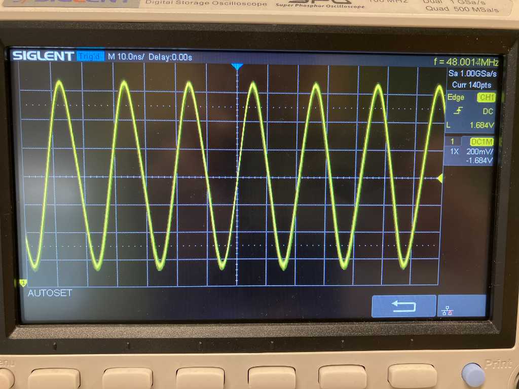
Let’s set GCLK4 the same way as GCLK0 so that I can measure if it outputs 48Mhz. If it does, I’m confident that the CPU clock GCLK0 is set correctly as well.
void setup48MhzUSBClockRecoveryMode(){
/* !!! removed some important code for clarity /*

  /* temporarily set 48MHz clock to GCLK4 as well and output to a pin to check accuracy. */
  GCLK->GENCTRL.reg =
      GCLK_GENCTRL_ID(4) |
      GCLK_GENCTRL_SRC_XOSC32K |
      GCLK_GENCTRL_IDC |
      GCLK_GENCTRL_GENEN |
      /* Enable outputting the clock to an I/O pin. */
      GCLK_GENCTRL_OE;

  /* Wait for the write to complete */
  while(GCLK->STATUS.bit.SYNCBUSY);
  PORT->Group[1].DIRSET.reg = (1 << 10);
  PORT->Group[1].PINCFG[10].reg |= PORT_PINCFG_PMUXEN;
  PORT->Group[1].PMUX[10 >> 1].bit.PMUXE |= PORT_PMUX_PMUXE_H;

}
Oscilloscope output. That’s a nice 48 MHz clock.
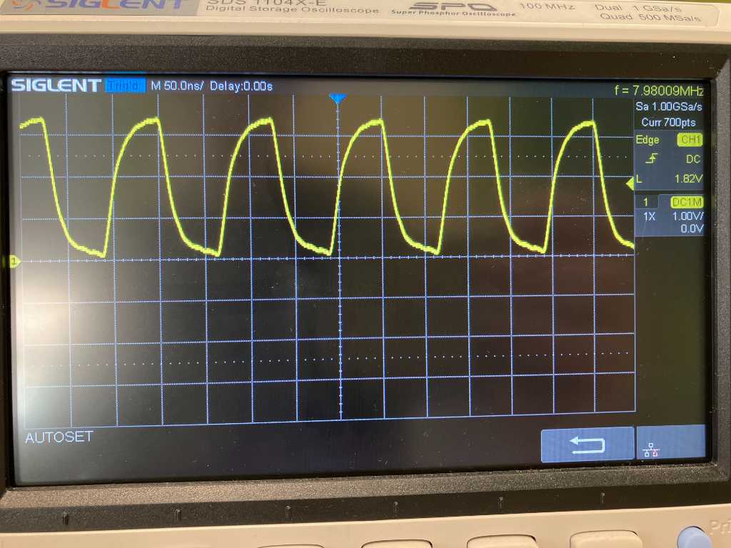
GCLK1 is used for the ADC clock and is set to 8Mhz. I wasn’t able to output this clock to a pin at the same time as setting it to the ADC. So I used the same settings for GCLK4 and checked that:
void setup8MhzGCLK(){
  // from https://blog.thea.codes/understanding-the-sam-d21-clocks/
  /* Configure GCLK1's divider - in this case, no division - so just divide by one */
  GCLK->GENDIV.reg =
      GCLK_GENDIV_ID(1) |
      GCLK_GENDIV_DIV(1);

  /* Setup GCLK1 using the internal 8 MHz oscillator */
  GCLK->GENCTRL.reg =
      GCLK_GENCTRL_ID(1) |
      GCLK_GENCTRL_SRC_OSC8M |
      /* Improve the duty cycle. */
      GCLK_GENCTRL_IDC |
      GCLK_GENCTRL_GENEN;

  /* Wait for the write to complete */
  while(GCLK->STATUS.bit.SYNCBUSY) {};

  // temporarily set 8MHz clock to GCLK4 as well and output to a pin to check accuracy.
  GCLK->GENDIV.reg =
      GCLK_GENDIV_ID(4) |
      GCLK_GENDIV_DIV(1);
  GCLK->GENCTRL.reg =
      GCLK_GENCTRL_ID(4) |
      GCLK_GENCTRL_SRC_OSC8M |
      GCLK_GENCTRL_IDC |
      GCLK_GENCTRL_GENEN |
      /* Enable outputting the clock to an I/O pin. */
      GCLK_GENCTRL_OE;

  /* Wait for the write to complete */
  while(GCLK->STATUS.bit.SYNCBUSY);
  PORT->Group[1].DIRSET.reg = (1 << 10);
  PORT->Group[1].PINCFG[10].reg |= PORT_PINCFG_PMUXEN;
  PORT->Group[1].PMUX[10 >> 1].bit.PMUXE |= PORT_PMUX_PMUXE_H;

}
Again a solid 8 MHz clock. Actually a bit under 8 MHz :-)
Now let’s set the other timers.
This is a bit of a pain because the SAMD21 combines timers and counters. I don’t want to use a library but examples on the internet are scarce. With a bit of help of thea.codes blog, the datasheet, and lot’s of wrong examples that copilot AI spit out, I was able to get hardware timer TC3, TC4 and TC5 to work nicely. I check it with a oscilloscope by toggling a pin.
To do the toggling with minimal impact on time, I directly manipulate the PORT registers instead of using Arduinos digitalWrite(). The commands to use are:
#define TESTPIN PORT_PB10 // temp test pin
PORT->Group[1].DIRSET.reg |= TESTPIN; // set test pin as output

PORT->Group[1].OUTCLR.reg = TESTPIN; // turn off TEST pin
PORT->Group[1].OUTSET.reg = TESTPIN; // turn test pin on
PORT->Group[1].OUTTGL.reg = TESTPIN; // toggle TEST pin
This is the code where the toggling happens in their respective interrupt handlers:
#define CPU_HZ 48000000 // The cpu clock is running at 48 MHz
#define TICK_HZ_1MS 1000 // We want a 1 ms tick.
#define COUNTS_PER_TICK_1MS (CPU_HZ / TICK_HZ_1MS) // This is the number of clock cycles per tick
#define TICK_HZ_1US 1000000 // We want a 1 us tick.
#define COUNTS_PER_TICK_1US (CPU_HZ / TICK_HZ_1US) // This is the number of clock cycles per tick
#define TICK_HZ_ADC 20000 // We want a 200 us tick for the ADC.
#define COUNTS_PER_TICK_ADC (CPU_HZ / TICK_HZ_ADC) // This is the number of clock cycles per tick


#define TESTPIN PORT_PB10 // temp test pin
void TC3_Handler() {
  //  PORT->Group[1].OUTTGL.reg = TESTPIN; // toggle TEST pin to be able to check with oscilloscope
  // Clear the interrupt
  TC3->COUNT16.INTFLAG.bit.MC0 = 1;
}
void TC4_Handler() {
  // PORT->Group[1].OUTTGL.reg = TESTPIN; // toggle TEST pin to be able to check with oscilloscope
  // Clear the interrupt
  TC4->COUNT16.INTFLAG.bit.MC0 = 1;
}
void TC5_Handler() {
  PORT->Group[1].OUTTGL.reg = TESTPIN; // toggle TEST pin to be able to check with oscilloscope
  // Clear the interrupt
  TC5->COUNT16.INTFLAG.bit.MC0 = 1;
}


void setup() {
    PORT->Group[1].DIRSET.reg |= TESTPIN; // set test pin as output
    // Set up the generic clock (GCLK4) used to clock timers
    GCLK->GENDIV.reg = GCLK_GENDIV_DIV(1) |          // Divide the 48MHz clock source by divisor 1: 48MHz/1=48MHz
                       GCLK_GENDIV_ID(4);            // Select Generic Clock (GCLK) 4
    while (GCLK->STATUS.bit.SYNCBUSY);               // Wait for synchronization

    GCLK->GENCTRL.reg = GCLK_GENCTRL_IDC |           // Set the duty cycle to 50/50 HIGH/LOW
                        GCLK_GENCTRL_GENEN |         // Enable GCLK4
                        GCLK_GENCTRL_SRC_DFLL48M |   // Set the 48MHz clock source
                        GCLK_GENCTRL_ID(4);          // Select GCLK4
    while (GCLK->STATUS.bit.SYNCBUSY);               // Wait for synchronization

    // Feed GCLK4 to TC3
    GCLK->CLKCTRL.reg = GCLK_CLKCTRL_CLKEN |         // Enable GCLK4
                        GCLK_CLKCTRL_GEN_GCLK4 |     // Select GCLK4
                        GCLK_CLKCTRL_ID_TCC2_TC3;     // Feed the GCLK4 to TC3 (and TCC2)
    while (GCLK->STATUS.bit.SYNCBUSY);               // Wait for synchronization

    // Feed GCLK4 to TC4 and TC5
    GCLK->CLKCTRL.reg = GCLK_CLKCTRL_CLKEN |         // Enable GCLK4
                        GCLK_CLKCTRL_GEN_GCLK4 |     // Select GCLK4
                        GCLK_CLKCTRL_ID_TC4_TC5;     // Feed the GCLK4 to TC4 and TC5
    while (GCLK->STATUS.bit.SYNCBUSY);               // Wait for synchronization

    // specific for TC3: 1ms
    TC3->COUNT16.CTRLA.reg |= TC_CTRLA_MODE_COUNT16;  // Set Timer counter Mode to 16 bits
    while (TC3->COUNT16.STATUS.bit.SYNCBUSY);         // Wait for synchronization

    TC3->COUNT16.CTRLA.reg |= TC_CTRLA_WAVEGEN_MFRQ;  // Set TC as Match Frequency
    while (TC3->COUNT16.STATUS.bit.SYNCBUSY);         // Wait for synchronization

    TC3->COUNT16.CC[0].reg = COUNTS_PER_TICK_1MS;     // Set the TC3 CC0 register as the TOP value in match frequency mode
    while (TC3->COUNT16.STATUS.bit.SYNCBUSY);         // Wait for synchronization

    // Enable the TC3 interrupt request
    TC3->COUNT16.INTENSET.bit.MC0 = 1;
    while (TC3->COUNT16.STATUS.bit.SYNCBUSY);         // Wait for synchronization

    // Enable TC3
    TC3->COUNT16.CTRLA.reg |= TC_CTRLA_ENABLE;        // Enable TC3
    while (TC3->COUNT16.STATUS.bit.SYNCBUSY);         // Wait for synchronization

    // Enable the TC3 interrupt vector use priority 2
    NVIC_SetPriority(TC3_IRQn, 2);                    // Set the NVIC priority for TC3 to 2
    NVIC_EnableIRQ(TC3_IRQn);

    // specific for TC4: 1us
    TC4->COUNT16.CTRLA.reg |= TC_CTRLA_MODE_COUNT16;  // Set Timer counter Mode to 16 bits
    while (TC4->COUNT16.STATUS.bit.SYNCBUSY);         // Wait for synchronization

    TC4->COUNT16.CTRLA.reg |= TC_CTRLA_WAVEGEN_MFRQ;  // Set TC as Match Frequency
    while (TC4->COUNT16.STATUS.bit.SYNCBUSY);         // Wait for synchronization

    TC4->COUNT16.CC[0].reg = COUNTS_PER_TICK_1US;     // Set the TC4 CC0 register as the TOP value in match frequency mode
    while (TC4->COUNT16.STATUS.bit.SYNCBUSY);         // Wait for synchronization

    // Enable the TC4 interrupt request
    TC4->COUNT16.INTENSET.bit.MC0 = 1;
    while (TC4->COUNT16.STATUS.bit.SYNCBUSY);         // Wait for synchronization

    // Enable TC4
    TC4->COUNT16.CTRLA.reg |= TC_CTRLA_ENABLE;        // Enable TC3
    while (TC4->COUNT16.STATUS.bit.SYNCBUSY);         // Wait for synchronization

    // Enable the TC4 interrupt vector use priority 0
    NVIC_SetPriority(TC4_IRQn, 0);                    // Set the NVIC priority for TC4 to 0
    NVIC_EnableIRQ(TC4_IRQn);

    // specific for TC5: 200us
    TC5->COUNT16.CTRLA.reg |= TC_CTRLA_MODE_COUNT16;  // Set Timer counter Mode to 16 bits
    while (TC5->COUNT16.STATUS.bit.SYNCBUSY);         // Wait for synchronization

    TC5->COUNT16.CTRLA.reg |= TC_CTRLA_WAVEGEN_MFRQ;  // Set TC as Match Frequency
    while (TC5->COUNT16.STATUS.bit.SYNCBUSY);         // Wait for synchronization

    TC5->COUNT16.CC[0].reg = COUNTS_PER_TICK_ADC;     // Set the TC5 CC0 register as the TOP value in match frequency mode
    while (TC5->COUNT16.STATUS.bit.SYNCBUSY);         // Wait for synchronization

    // Enable the TC5 interrupt request
    TC5->COUNT16.INTENSET.bit.MC0 = 1;
    while (TC5->COUNT16.STATUS.bit.SYNCBUSY);         // Wait for synchronization

    // Enable TC4
    TC5->COUNT16.CTRLA.reg |= TC_CTRLA_ENABLE;        // Enable TC5
    while (TC5->COUNT16.STATUS.bit.SYNCBUSY);         // Wait for synchronization

    // Enable the TC5 interrupt vector use priority 1
    NVIC_SetPriority(TC5_IRQn, 1);                    // Set the NVIC priority for TC5 to 1
    NVIC_EnableIRQ(TC5_IRQn);
}

void loop() {
    // nothing here
}
note that the timers are set to a specific priority to aid me in my Marimbatron firmware.
This codes create a 1us (TC4), 200us (TC5) and 1ms (TC3) timer.
Find the sketch here in my final-project repo
Note that a 1us timer turned out not to be helpful. See this stackexchange post where the following is mentioned:
- The CPU clock is set to 48 Mhz
- a 1 us timer means it runs at 1 Mhz
- this means the interrupt occurs every 48 CPU clockcycles
- Cortex-M0+ takes 15 clockcycles to get into the interrupt routine, assuming the bus is free
- plus another 13 cycles to leave the interrupt
- This totals to 28 cycles, leaving 20 clockcycles to handle whatever is in the ISR function
- The remainder of the cycles can be used for other stuff. e.g. other interrupts.
A great blog on interrupt latency in the ARM cortex family can be found at arm.com.
With this said, there’s almost no cycles left to do anything. The 1us interrupt uses too much CPU time for anything else to happen. This means I cannot use such a fast timer ISR combined with any useful programs :-). But taking things a bit slower should work fine in my situation.
V3 fast reading with ISR timers
Next is to check how fast the ISR can go. I do this by toggling the output of a pin and check the signal on an oscilloscope.
I’ve set TC3 (my “main” timer) to 100us instead of 1us. I also removed the 1ms timer and use the main timer to set my intervals (just do everything on this clock instead of using another clock that consumes CPU time).
The microcontroller seems to happily measure all 19 sensors at a speed of 200us to trigger the measurement loop. So all 19 sensors are measured within 200us.
As soon as one of the sensors trigger the threshold value, this specific sensor is measured much faster in order to catch it’s peak value. In the code below I’m toggling the output of my testpin to check if this is really happening and to check at what speed this occurs.
      currentMeasurement = readADC(true); // true = first measurement should be disregarded due to channel change
      if (currentMeasurement < padThreshold) { // measurement below threshold = hit detected. Start peak detection for scantime us.
        uint32_t scanTime = pads[i].getScanTime();
        uint32_t peakMeasurement = padThreshold;
        while ((unsigned long)(micros_counter - startScan) <= scanTime) { // stay measuring for as long as scanTime is. Again using micros_counter overflow prevention
          PORT->Group[1].OUTTGL.reg = TESTPIN; // toggle TEST pin to be able to check with oscilloscope
          currentMeasurement = readADC(false); // disregarding first measurement is not neccesary because we didn't change the input channel
          if (currentMeasurement < peakMeasurement) { // peak detection for local minimum
            peakMeasurement = currentMeasurement;
          }
        }
The oscilloscope output (set to single trigger to keep the measurements on the screen):
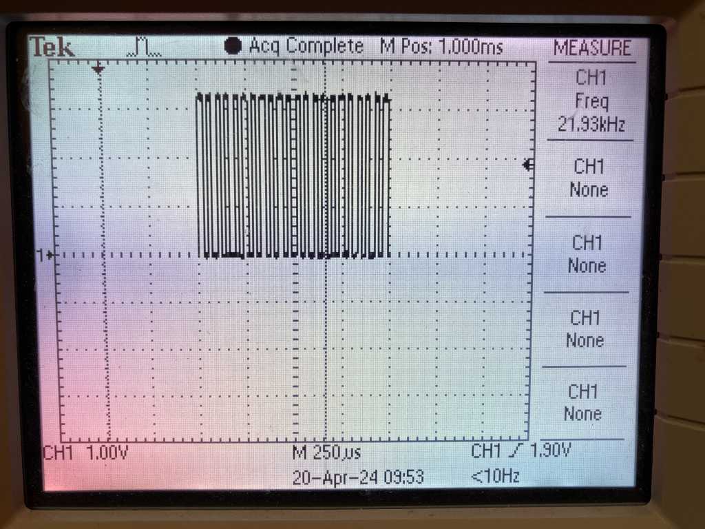
The frequency of this burst is 21,93 kHz. At every fast measurement, the pin output is inverted, so the actual ADC measurement frequency is twice this value: 43,86 kHz. This equals to one measurement every 23 microseconds. That is actually very good! A hard hit gets to it’s peak in around 600 us. Every 200 microseconds the sensor is checked if it triggers the threshold. Worst-case the hit was just before the last check, leaving 400 microseconds worth of speed-measurements. With 23 microseconds per measurement, the microcontroller can do 17 measurements up until the peak is reached. To me that sounds enough to catch the height of the peak!
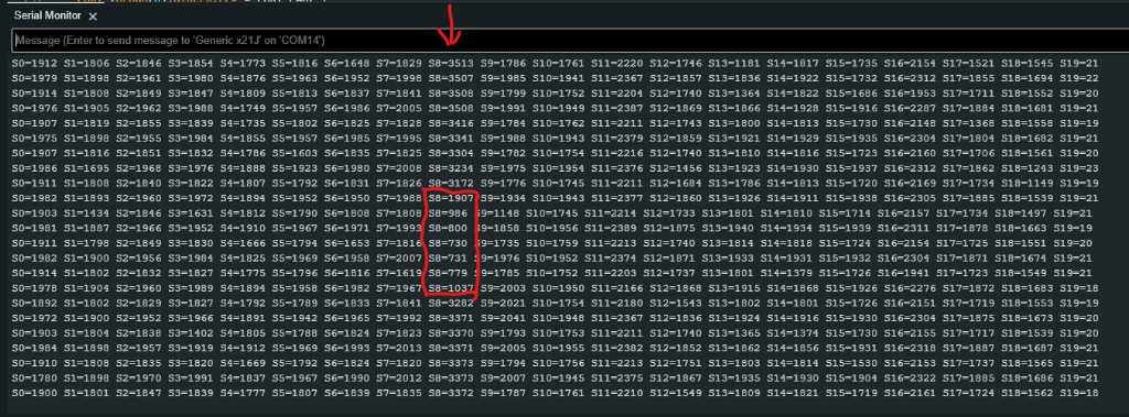
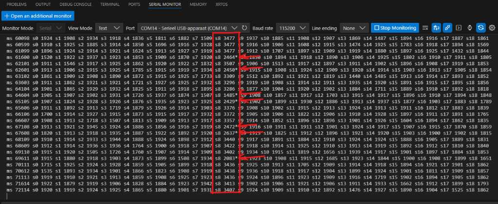
In the serial monitor output you can see all 19 sensor outputs. In the red rectangle you see sensor 8. When a hit is detected, a * is printed next to the velocity. Every 50ms the sensor array is read out in the main loop and printed to the serial port:
This is a video of me hitting the pad. The red LED on the PCB blinks every 100ms (toggled on/of in the 50ms event in the main loop). As soon as a hit is detected, the green LED is turned on. It is turned of in the next 50ms event. As you can see this looks promising!
Of course I haven’t programmed I2C communication to the main controller and WS2812B LED control in this program. Adding this might affect the maximum speeds that can be achieved. On the other hand, I’m using Serial communication now and that’s not going to be active on this sensorboard in “production” mode. And I haven’t “unrolled” the for loop in the ISR yet. But we’ll find out how much influence this will have.
I2C communication
There are 3 pads on the sensor board that I can populate with 0 ohm resistors and read their value as digital input. That way I can define the I2C address of each board (max 2^3 = 8 addresses available).
Good info on I2C can be found in the arduino docs. I read this to get a quick start.
The Wire library is what Arduino uses to communicate with I2C devices. It is included in all board packages, so you don’t need to install it manually in order to use it.
What you need to know is that in the past I2C was all about master and slaves. Now the Arduino docs talk about controller and peripherals. I actually like Main and Secondary better because in Dutch, a similar word to peripheral isn’t really used that much. Also with Main and Secondary, the abbreviations MISO and MOSI are still useable.
The examples have sketches on controller reader and controller writer. Both of which are exactly what I want to accomplish. Nice kick start!
I’m going to first use my SAMD11C14A test PCB that I made in programming week as the I2C main. My Sensor PCB with the SAMD21J18A will be the I2C secondary.
The SAMD11C14A has PA14 as SDA and PA15 as SCL, which I wired to a connector. No more work on that.
The SAMD21J18A has multiple pins that can be used for I2C. It also has multiple SERCOMs so you can even have multiple I2C busses simultaneously. The Arduino framework (by means of the variant.h file) has default pins set up to be used for I2C. For the SAMD21J18A (using ArduinoCore-fab-sam), the default pins for I2C (also known as wire.h) are PA16 and PA17. But I’m using those. I could have. Would have made my life easier. But I didn’t check the default pins when I routed my board. So I routed them to PA12 and PA13 (SERCOM2)…
Fortunately, the variant.h also creates a wire1 and sets PA12 and PA13 to wire1. This means I can use it like this:
#include <Wire.h>
void setup() {
Wire1.begin();
}
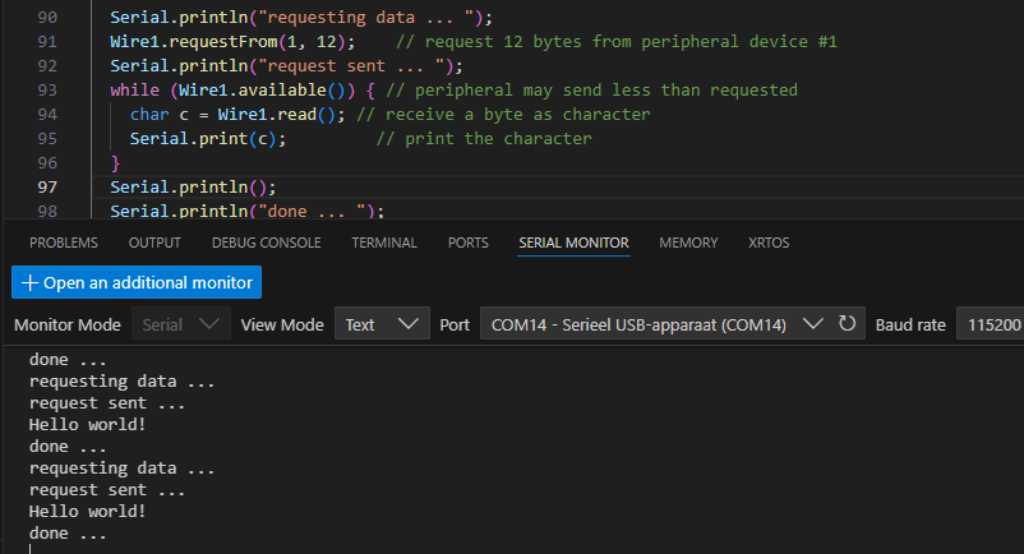
void loop() {
Serial.println("requesting data ... ");
Wire1.requestFrom(1, 12); // request 12 bytes from peripheral device #1
Serial.println("request sent ... ");
while (Wire1.available()) { // peripheral may send less than requested
char c = Wire1.read(); // receive a byte as character
Serial.print(c); // print the character
}
Serial.println("done ... ");}
This only works if you specifically enable two I2C ports in the Arduino board configuration! You’ll get an error if you don’t set this correctly.
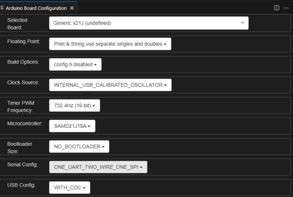
Find this in Arduino IDE under Tools -> Serial Config -> ONE_UART_TWO_WIRE_ONE_SPI.
Or in VSCode using Arduino plugin:
So I got my microcontrollers connected to my computer, used the SAMD11 as secondary, the SAMD21 as main and voila:
On the main
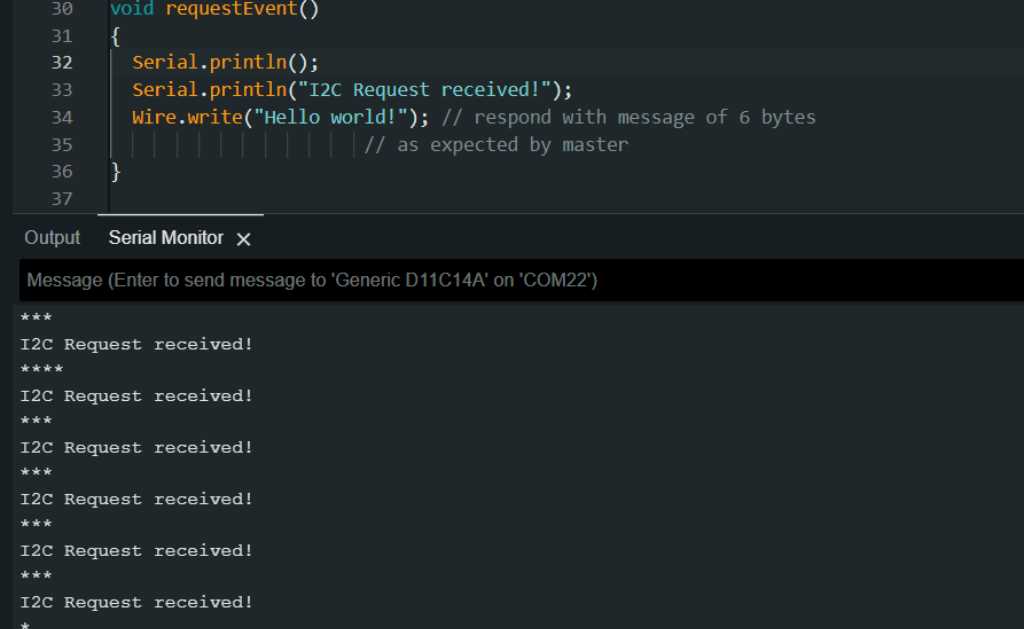
On the secondary
Find the code in these repos:
Master code
Secondary code
With that out of the way, it’s time to send real data!
The thing that gets this to work is to do this on the I2C main:
  Wire.requestFrom(1, 5);    // requesting 5 bytes from address 1. Max number of bytes in a single transmission cannot be more than 32.
  while(Wire.available()) {
      sensorNumber = Wire.read(); // Wire.read reads 1 byte at a time. uint8_t is 1 byte.
      sensorVelocity = Wire.read() | (Wire.read() << 8) | (Wire.read() << 16) | (Wire.read() << 24); // sensorVelocity is uint32_t, which is 4 bytes. So need to combine 4 reads into one uint32_t.
      Serial.print(sensorNumber);         // Print the value
      Serial.print(" ");
      Serial.println(sensorVelocity);
      if (sensorNumber < 255) {
        Serial.print("Hit on sensor "); Serial.print(sensorNumber); Serial.print(" -> "); Serial.println(sensorVelocity);
        Serial.println("Sending note on");
        noteOn(0, 48, 64);   // Channel 0, middle C, normal velocity
        delay(100);
        Serial.println("Sending note off");
        noteOff(0, 48, 64);  // Channel 0, middle C, normal velocity
      }
      else{
        Serial.println("no hit");
      }
  }
and do this on the I2C Secondary ISR:
void I2CEvent(){ // send [255, 0, 0, 0, 0] when no hit is detected. Otherwise send sensor number and velocity of just 1 sensor and reset the hit state of that sensor
  uint32_t velocity;
  bool hitDetected = false;
  uint8_t data[] = {255,0,0,0,0};
  // Serial.println("Received I2C event");
  for (uint8_t i = 0; i < sensorArrayLength; i++) {
    if (pads[i].getHit()){ // if true: hit is detected
      hitDetected = true;
      velocity = pads[i].getVelocity();
      Serial.print("HIT s"); Serial.print(i); Serial.print(" ");Serial.print(velocity);
      Serial.println();
      // set sensor number and velocity to data variable when hit is detected
      data[0] = i;
      data[1] = velocity & 0xFF;
      data[2] = (velocity >> 8) & 0xFF;
      data[3] = (velocity >> 16) & 0xFF;
      data[4] = (velocity >> 24) & 0xFF;
      PORT->Group[1].OUTSET.reg = GREENLEDPIN; // turn green led pin on
      flashLED = true;
      pads[i].setHit(false); // reset hit
      break; // break the for loop
    }
  }
  Wire1.write(data, 5); // even when no hit is detected an answer will still be send (255, 0, 0, 0, 0)
}
This example uses the SAMD11C14-I2Cmaster-MIDIout on the SAMD11 board and sensormodule_FW_v4 on the SAMD21 sensorboard.
Find the code in these repos:
SAMD11C14-I2Cmaster-MIDIout
sensormodule_FW_v4
I2C Deadlock (bus busy issue)
tl;dr
The I2C deadlock problem cannot be fundamentally avoided.
I found out I2C has an inherent issue. If you search on “weird I2C behaviour”, “Dead-lock”, “Lock out” or any of those terms, you’ll find posts describing them.
In default state, the SDA and SCL should be high. Both main as well as peripherals can drive SDA line low during transmissions. And during transmissions the protocol has acknowledgement states to indicate that transmission was done properly, etc.
But what happens when you reset the main WHILE the peripheral is transmitting? The main should provide a clock on SCL so the peripheral can transmit. But the main was reset. So no clock. So the peripheral doesn’t know what to do. If the peripheral has driven the SDA low, this line will not recover to high state, because a clock is needed to do that. And when the SDA is held low, the main controller won’t do anything. It waits for the peripheral to release it. See the issue? A proper deadlock. And because in Arduino framework the Wire library doesn’t have a timeout, the main peripheral won’t recover from this deadlock. Not even after a reset. Apparently, there are other situeations that can result in this deadlock (e.g. noisy environment).
The deadlock issue is also described by Seeed studios in this post: https://www.seeedstudio.com/blog/2022/09/02/i2c-communication-protocol-and-how-it-works/
The only way to solve this is to unplug power so the peripheral will reset. But you don’t want end customers to powercycle. So the main controller should have a way to power cycle the I2C peripherals. I didn’t know about this so I don’t have that on my PCB…
According to a comment in this reddit post This issue isn’t a bug:
3.1.16 of the I2C specification:
In the unlikely event where the clock (SCL) is stuck LOW, the preferential procedure is to reset the bus using the HW reset signal if your I2C devices have HW reset inputs. If the I2C devices do not have HW reset inputs, cycle power to the devices to activate the mandatory internal Power-On Reset (POR) circuit.

If the data line (SDA) is stuck LOW, the controller should send nine clock pulses. The device that held the bus LOW should release it sometime within those nine clocks. If not, then use the HW reset or cycle power to clear the bus.
So the official specification says that you should have a power switch to cycle the power to reset I2C chips. RTFM?
Anyway, this is a serious issue. Especially when your programming and debugging your microcontrollers, because you’ll reset them at random moments.
I found one possible solution that seems solid. If I have time i’ll implement this. The idea is that when the main is reset, the very first thing it does is to set the I2C SDA and SCL lines as inputs. Next, it checks the status of the SDA line are checked. If it is low, there is a deadlock situation. The SCL pin is now set at output and several clock pulses are generated. This will make the peripheral that holds the SDA line busy to “continue” to send the data that it wanted to send. When this is all done, the SDA and SCL lines are configured as “normal” inputs.
https://community.nxp.com/t5/Kinetis-Microcontrollers/I2C-device-dead-lock-recovery/m-p/304368 in this post it is described:
If the reset button is pressed during the time that the accelerometer is sending the I2C ACK it will block in that state and continue driving the SDA line. After the reset is is not possible to use the I2C bus since it is continuously in the busy state and further resets of the processor don't help - a power cycle does however since it resets the slave device.
...
a reliable solution was investigated that would automatically detect the state and resolve. The solution is as follows:

- rather than configure the I2C pins when the I2C interface is initialised they are left as inputs with pull-ups enabled

- the first time that the I2C bus is to be used for transmission (transmission takes place as first operation of any read or write) the bus state is checked.

- if it is detected in the busy state, the SCL pin is set to an output and clocks generated until the busy state no longer exists (the clocks remove the slave from its present ACK state - several clocks may be required)

- the pins are then set to their final I2C peripheral usage

- once the pins are set no further checking is required for subsequent I2C use and normal interrupt or DMA driven modes are possible

The result was that, although the I2C slave was still holding the bus in about 15% of reset cases, the automatic detection/recovery reliably resolved it with no user code intervention.
...
for reference, the detection/recovery code for the pins as used by the accelerometer on the KL25 freedom board is show below.
//Pin configuration during I2C initialisation is restricted to ensuring they are inputs:
_CONFIG_PORT_INPUT_FAST_HIGH(E, (PORTE_BIT25 | PORTE_BIT24), (PORT_ODE | PORT_PS_UP_ENABLE));

//On first use the following code checks the bus state and recovers if neede, followed by setting the final peripheral pin functions:

while (_READ_PORT_MASK(E, PORTE_BIT25) == 0) {   // if the SDA line is low we clock the SCL line to free it**

    _CONFIG_DRIVE_PORT_OUTPUT_VALUE_FAST_HIGH(E, PORTE_BIT24, 0, (PORT_ODE | PORT_PS_UP_ENABLE)); // set output '0'**

    fnDelayLoop(10);

    _CONFIG_PORT_INPUT_FAST_HIGH(E, PORTE_BIT24, (PORT_ODE | PORT_PS_UP_ENABLE));

    fnDelayLoop(10);

}

_CONFIG_PERIPHERAL(E, 25, (PE_25_I2C0_SDA | PORT_ODE | PORT_PS_UP_ENABLE)); // I2C0_SDA on PE25 (alt. function 5)**

_CONFIG_PERIPHERAL(E, 24, (PE_24_I2C0_SCL | PORT_ODE | PORT_PS_UP_ENABLE)); // I2C0_SCL on PE24 (alt. function 5)**
My function to do this (arduino framework style) is:
void checkAndSolveI2CDeadlock(){
  // Pin configuration during I2C initialisation are set as inputs.
  // PIN_WIRE_SDA (16u)-> PA16
  // PIN_WIRE_SCL (17u)-> PA17
  Serial.println("Checking I2C deadlock");
  // set PA16 to input, enabling pull resistor and setting it to pull-up.
  PORT->Group[0].DIRCLR.reg = PORT_PA16;
  PORT->Group[0].PINCFG[PIN_PA16].reg = PORT_PINCFG_PULLEN | PORT_PINCFG_INEN;
  PORT->Group[0].OUTSET.reg = PORT_PA16;
  // set PA17 to input, enabling pull resistor and setting it to pull-up.
  PORT->Group[0].DIRCLR.reg = PORT_PA17;
  PORT->Group[0].PINCFG[PIN_PA17].reg = PORT_PINCFG_PULLEN | PORT_PINCFG_INEN;
  PORT->Group[0].OUTSET.reg = PORT_PA17;

  if (~PORT->Group[0].IN.reg & PORT_PA16 ? 1 : 0) {
    Serial.println("I2C deadlock detected!");
    PORT->Group[0].DIRSET.reg = PORT_PA17; // set SCL pin as output
    //following code checks the bus state and recovers if needed
    while(~PORT->Group[0].IN.reg & PORT_PA16 ? 1 : 0) { // if the SDA line is low we clock the SCL line to free it
      PORT->Group[0].OUTCLR.reg = PORT_PA17; // pull SCL low
      delay(10);
      PORT->Group[0].OUTSET.reg = PORT_PA17; // pull SCL high
      delay(10);
    }
  }
}
I2C pull up resistor
The I2C communication relies on pull up resistors on SDA and SCL (so one between SDA and VCC and one between SCL and VCC). The value of these resistors is a point of debate. It is said that the default value should be 4.7kOhm. But it depends on the wire lengths. The higher the resistor, the more the capacitance and this resistor act as a low-pass filter. This will cause the pulses to be less square (they don’t have sharp edges, but rounded corners instead). If this is too much, the devices won’t be able to read the I2C data anymore. Two things can be done to prevent this: limit the I2C speed or use a lower resistor value. But if the resistor value is too low, the pull-up is “too weak”. That means that the resistor can’t pull the SDA and SCL lines to VCC enough. And that causes the I2C bus to malfunction too. I haven’t seen ways (rules of thumb) to estimate what the value should be.
I started off with 4.7 kOhm. When 1 sensor board was connected, this worked fine (at 100 kbit/s I2C speed). But when I connected the 2nd sensor board, every once in a while, the I2C bus would lock up. When I connected the 3rd board, this happened sooner, but irregular. When I connected the 4th board, the I2C bus would become unresponsive at all. It took a long time to figure out that this was because of the pullup resistance. I thought it was due to the I2C deadlock (described above). So I first investigated (and added code to solve) that. The bus kept getting unresponsive. So I lowered the resistance value so about 1 kOhm. All is happy now! But you really don’t want to go lower than 1k because this value draws about 3.3mA @ 3.3V. The SAMD21 can source 2mA continuous. When I2C is “active”, the pin is pulled low and current will flow. So the 3.3mA is not continuous but still I don’t want to overdo it.
WS2812B LED control
Each pressure sensor has one WS2812B RGB LED. The microcontroller will have to drive these LEDs so things look nice :D
Controlling it is usually done either thru
I found out that Adafruit Neopixel library (and fastled most probably does the same) disables interrupts to be able to get the timing of the WS2812B protocol correct. This interferes with my timer ISR of the ADC! So I have to find a way around this.
I found this Adafruit Neopixel ZeroDMA library that should not have this issue. Instead it relies on DMA transfer (direct memory access) to get data to the neopixels. This is usually called a “non-blocking” library, i.e. it doesn’t prevent the processor to do other work while it sends out the WS2812B commands.
Unfortunately, this only works on very specific Adafruit boards and only if the neopixel data ouput pin of the microcontroller is tied to a specific pin. This is because the library uses SERCOM peripherals for SPI output, and the hardware only supports this on specific pins (plus, some SERCOMs are in use for Serial, I2C, etc.). But not just that. As per the comments in the pins.h file:
SAMD21/51 can actually handle
SPI DMA on many more pins than are indicated here, but the code design
INTENTIONALLY limits it to specific pins -- one "curated" pin per SERCOM.
Not for technical reasons, but as a matter of documentation and clarity.
So much for using this library for custom boards. I tried and failed. But fortunately, in the very corner of the internet I found this blogpost: https://www.lucadavidian.com/wifi-controlled-neo-pixels-strips/. The explanation of how non-blocking WS2812B is using SPI is so good that I copied the interesting part below so it doesn’t get lost when the internet disappears. But all props to the author of this!
start of copied secion
Driving NeoPixels with the SPI
NeoPixels are integrated light sources in which a RGB led is packaged with a driver chip (the WS2812/WS2812B or the SK6812) and controlled by a single-wire. They can be used singularly or most often come in strips of a variable number of elements. The protocol is simple, a 24-bit RGB color (8 bits per color) is sent through the only data wire with a timing specified in the chip datasheet: data transmission is allowed up to 800KHz and coding a 0 or a 1 is just a matter of generating a square wave with the correct duty cycle:

If we need to drive a strip of leds we need to send the color for the first led, then the second and so on until the color for the last led of the strip has been sent. When we’re done we simply latch the data by sending a 300 microseconds worth of zeroes, then the leds lights up. Timing is not very strict (the chip allows for little tolerance) and different driver chips specify different timing characteristics but they all work the same (see the datasheet for the various driver chips at the end of the article). Since timing is so crucial we could write some time-critical code in assembly to toggle the level of the data pin in order to generate the correct signal to drive the leds. This approach would be difficult to integrate with the other components, since we want to animate the leds and at the same time the application need to listen for commands over the UART (and possibly do something else). Since the datasheet allows for a little tolerance in the signal timing we can use the SPI to generate a bit pattern that resembles the square wave that corresponds to a zero or a one code. Each bit is expanded into three bits: if we want to send a 1 code we send a 110 pattern, if we want to send a 0 code we send a 100 pattern, while the SPI is configured with a speed of 800 KHz * 3 = 2.4 MHz:

At the end of the data we need to provide the latch signal, so the SPI will send 90 bytes filled with zeroes. We send data using the direct memory access capability of the SAMD21, freeing the CPU from loading the SPI register with data. So if the strip contains N leds we need a buffer of N * 3 * 3 (each led needs three bytes and each bit is expanded into three bits) + 90 bytes for latching. Since it’s from this buffer that the DMA controller fetches the data for the SPI I’ll call it the DMA buffer. Another buffer is created which is used as a framebuffer and is updated by the application: this buffer contains just the original color data (3 bytes per led pixel), so it’s easy to read from and write to (in the same way a display framebuffer is updated); each byte in this framebuffer is then expanded into three bytes by indexing into a lookup table (the table has 256 entries, one for each possible byte) and copied into the DMA buffer, ready to be sent out by the SPI:

The DMA controller
The DMA controller of the SAMD21 allows all kinds of data transfer (peripheral to memory, memory to peripheral, memory to memory and peripheral to peripheral), has 12 configurable channels and use transfer descriptors to configure the tranfers. The DMA controller is configured to receive requests from the SPI peripheral whenever it need to send data (the SPI triggers DMA data transfers). Data is tranferred from the DMA buffer to the SPI data register continuously (one byte at the time) even if the data stays the same (to avoid glitches in the light patterns); the DMA channel is re-enabled after each DMA transfer complete interrupt. I provide a simple way to add channels to the DMA controller, even if in this application we need only one for the SPI:
#define MAX_DESCRIPTORS 2

/* statically allocated arrays of DMA transfer descriptors (descriptor section and write back section */
__attribute__((__aligned__(16))) static DmacDescriptor descriptor_section[MAX_DESCRIPTORS];
__attribute__((__aligned__(16))) static DmacDescriptor write_back_section[MAX_DESCRIPTORS];
static int used_channels = 0;  // used channels

int volatile dma_frame = 0;

void DMA_init(void)
{
    static int initialized = 0;

    if (!initialized)
    {
        /* enable peripheral clock */
        PM->APBBMASK.bit.DMAC_ = 1;

        /* enable AHB master clock */
        PM->AHBMASK.bit.DMAC_ = 1;

        /* configure DMA controller */
        DMAC->BASEADDR.reg = (uint32_t)descriptor_section;                    // descriptor memory section start
        DMAC->WRBADDR.reg = (uint32_t)write_back_section;                     // descriptor write-back memory section start
        DMAC->CTRL.bit.LVLEN0 = 1;                                            // enable level 0 priority
        DMAC->CTRL.bit.LVLEN1 = 1;                                            // enable level 1 priority
        DMAC->CTRL.bit.LVLEN2 = 1;                                            // enable level 2 priority
        DMAC->CTRL.bit.LVLEN3 = 1;                                            // enable level 3 priority

        /* DMA is initialized */
        initialized = 1;
    }
}

/* add the first least significant free channel with its descriptor */
void DMA_add_channel(int source, DmacDescriptor *descriptor)
{
    /* disable DMA if enabled */
    if (DMAC->CTRL.bit.DMAENABLE)
        DMAC->CTRL.bit.DMAENABLE = 0;
    while (DMAC->CTRL.bit.DMAENABLE)
        ;

    /* add transfer descriptor to transfer descriptor section (before enabling channel!) */
    memcpy(descriptor_section + used_channels * sizeof(DmacDescriptor), descriptor, sizeof(DmacDescriptor));

    /* configure and enable first least significant free channel */
    DMAC->CHID.bit.ID = used_channels++;                                  // use first free channel
    DMAC->CHCTRLB.bit.LVL = 0x00;                                         // channel priority level 0
    DMAC->CHCTRLB.bit.TRIGACT = 0x02;                                     // one trigger each beat transfer
    DMAC->CHCTRLB.bit.TRIGSRC = source;                                   // select trigger source
    DMAC->CHCTRLA.reg |= DMAC_CHCTRLA_ENABLE;                             // enable channel

    /* enable DMA block transfer complete interrupt */
    DMAC->CHINTENSET.bit.TCMPL = 1;                                       // enable DMA block transfer complete interrupt
    NVIC_EnableIRQ(DMAC_IRQn);                                            // enable DMA interrupt in NVIC
}

void DMA_enable(void)
{
    /* enable DMA controller */
    DMAC->CTRL.bit.DMAENABLE = 1;
}

void DMAC_Handler(void)
{
    for (int channel = 0 ; channel < used_channels ; channel++)  // check interrupt for every registered channel
    {
        DMAC->CHID.bit.ID = channel;
        if (DMAC->CHINTFLAG.bit.TCMPL && DMAC->CHINTENSET.bit.TCMPL)
        {
            if (DMAC->CHID.bit.ID == 0x00)   // handle SPI transfer complete interrupt
            {
                            DMAC->CHINTFLAG.bit.TCMPL = 1;                 // acknowledge interrupt
                DMAC->CHCTRLA.reg |= DMAC_CHCTRLA_ENABLE;      // re-enable DMA channel
                        }
        }
    }
}
A section in RAM is allocated for transfer descriptors (in this application we need just one but it can be extended to as many descriptors as needed). A DMA channel is configured and added for the SPI in the NeoPixel_init() function inside the NeoPixel.c file:
static uint8_t pixel_buffer[NUM_PIXELS * 3];             // 3 bytes per pixel (G-R-B)
static uint8_t dma_buffer[NUM_PIXELS * 3 * 3 + 90];      // each byte is expanded to 3 bytes + 90 bytes (zeros) for latching

void NeoPixel_init(void)
{
    /* initialize frame buffer */
    NeoPixel_clear_pixels();

    /* initialize DMA buffer */
    for (int i = 0 ; i < sizeof dma_buffer ; i++)
        dma_buffer[i] = 0x00;

    /* configure and enable DMA controller */
    /* set up transfer descriptor */
    DmacDescriptor descriptor;
    descriptor.DSTADDR.reg = (uint32_t)&SERCOM0->SPI.DATA;                // destination address is SPI DATA register
    descriptor.SRCADDR.reg = (uint32_t)(dma_buffer + sizeof dma_buffer);  // source address is the DMA buffer
    descriptor.DESCADDR.reg = 0;                                          // only one transfer descriptor
    descriptor.BTCTRL.bit.BEATSIZE = DMAC_BTCTRL_BEATSIZE_BYTE_Val;       // beat size is one byte
    descriptor.BTCTRL.bit.DSTINC = 0;                                     // destination address increment disabled
    descriptor.BTCTRL.bit.SRCINC = 1;                                     // source address increment enabled
    descriptor.BTCTRL.bit.STEPSEL = DMAC_BTCTRL_STEPSEL_SRC_Val;          // flexible source address increment size
    descriptor.BTCTRL.bit.STEPSIZE = DMAC_BTCTRL_STEPSIZE_X1_Val;         // source address increment is one byte
    descriptor.BTCTRL.bit.BLOCKACT = DMAC_BTCTRL_BLOCKACT_NOACT_Val;      // request interrupt at end of block transfer
    descriptor.BTCNT.reg = sizeof dma_buffer;                             // beat count
    descriptor.BTCTRL.bit.VALID = 1;                                      // descriptor is valid
    /* initialize DMA controller */
    DMA_init();
    /* add and enable SERCOM0 (SPI) channel */
    DMA_add_channel(DMA_SOURCE_SERCOM0, &descriptor);
    /* enable DMA */
    DMA_enable();

    /* initialize SPI */
    SPI_init();
}

So, at the beginning both the DMA buffer and the frame buffer (here called _pixel_buffer_) are empty (filled with zeroes, all leds off). The DMA is initialized, a channel linked to the SPI (SERCOM0) is added and the SPI initialized and enabled. The NUM_PIXELS macro is defined in _NeoPixel.h_ to select how many pixels the strip is made of. At this point the SPI is sending the contents of the DMA buffer on the data line, but we still have to “draw” on the framebuffer to display light patterns. The fundamental function is _NeoPixel_set_pixel()_:

/* set pixel color (pixel are numbered from 0 to NUM_PIXELS - 1) */
void NeoPixel_set_pixel(int pixel, uint8_t red, uint8_t green, uint8_t blue)
{
    if (pixel < 0 || pixel >= NUM_PIXELS)
        return;
    int n = pixel * 3;
    pixel_buffer[n] = green;
    pixel_buffer[n + 1] = red;
    pixel_buffer[n + 2] = blue;
}

After checking that the selected pixel is in range, the function draw the selected color into the framebuffer. To display the updated buffer we need to call _NeoPixel_update()_, which copies the pixel buffer into the DMA buffer, expanding the bytes by performing a table lookup into the expand array (the index into the expand array is the byte itself):

static const uint32_t bit_expand[256]; // lookup table for bit expansion

/* update DMA buffer */
void NeoPixel_update(void)
{
    for (int i = 0, j = 0 ; i < sizeof pixel_buffer ; i++, j += 3)
    {
        uint32_t expanded = bit_expand[pixel_buffer[i]];
        dma_buffer[j] = expanded >> 16;
        dma_buffer[j + 1] = expanded >> 8;
        dma_buffer[j + 2] = expanded;
    }
}

/* bit expansion lookup table */
static const uint32_t bit_expand[256] = {
    0b100100100100100100100100,
    0b100100100100100100100110,
    0b100100100100100100110100,
    0b100100100100100100110110,

        ..... other entries
        .....
};
The DMA continuously transfers data from the DMA buffer to the SPI data register, so as soon as the NeoPixel_update() function executes the leds are updated with the contents of the pixel buffer.
end of copied section
I couldn’t have explained it better. Also, please have a look at my code in the repo that uses the information above and outputs WS2812B commands through pin PA08. Note that I combined all functions into one big Arduino compatible file, because the original is not based on the Arduino framework.
Next is to change the pin because I’m using PA08 for other purposes. So I’ll have to change it to PB10. As noted above, DMA transfer using SPI only works on specific pins. The multiplexer of the pin has to be set to a SERCOM peripheral. And you have to use a pin that can be tied to a SERCOM PAD that can become a SPI MOSI (main output). This cannot only be done on specific pins, so check the datasheet. PB10 can be MOSI when it is connected to SERCOM4 in ALT peripheral. For that to happen the DOPO register has to be set to 0x01 (because PB10 is SERCOM4 PAD2).
in the function spi_init() you set this up as follows:
    /* enable peripheral clock */

    PM->APBCMASK.bit.SERCOM4_ = 1;


    /* enable generic clock */

    GCLK->CLKCTRL.bit.ID = GCLK_CLKCTRL_ID_SERCOM4_CORE_Val;     // configure generic clock for SERCOM4

    GCLK->CLKCTRL.bit.GEN = GCLK_CLKCTRL_GEN_GCLK0_Val;          // source is generic clock generator 0

    GCLK->CLKCTRL.bit.CLKEN = 1;                                 // enable generic clock

    /* select GPIO pins alternative function */

    PORT->Group[1].PINCFG[10].bit.PMUXEN = 1;                     // enable alternative function for pin PB10

    PORT->Group[1].PMUX[5].bit.PMUXE = MUX_PB10D_SERCOM4_PAD2;   // PB10 alternative function D (SERCOM4 pad 2)


    /* configure peripheral */

    SERCOM4->SPI.CTRLA.bit.DOPO = 0x01;                          // MOSI on pad 2

    SERCOM4->SPI.CTRLA.bit.CPHA = 0x00;

    SERCOM4->SPI.CTRLA.bit.CPOL = 0x00;                          // transfer mode 0

    SERCOM4->SPI.CTRLA.bit.DORD = 0x00;                          // MSB first

    SERCOM4->SPI.CTRLA.bit.MODE = 0x03;                          // SPI master operation

    SERCOM4->SPI.CTRLB.bit.CHSIZE = 0x00;                        // 8 bit character size

    SERCOM4->SPI.BAUD.reg = 9;                                   // SPI frequency 2.4 MHz (BAUD = gclk/(2*f_baud) - 1)

    /* enable peripheral */

    SERCOM4->SPI.CTRLA.reg |= SERCOM_SPI_CTRLA_ENABLE;
Also make sure to set the SPI DATA to SERCOM 4 (in NeoPixel_init()):
descriptor.DSTADDR.reg = (uint32_t)&SERCOM4->SPI.DATA; // destination address is SPI DATA register of sercom4
Next make sure to set the DMA Source correctly:
#define DMA_SOURCE_SERCOM0  0x02
#define DMA_SOURCE_SERCOM4  0x0A // datasheet 20.8.19 Channel control B -> Bits 13:8 – TRIGSRC[5:0] Trigger Source
This does it! I now have a WS2812B changing colors while consuming almost no processing power.
The source file of the non-blocking version on pin PA08 is here in my repo..
The source file of the non-blocking version on pin PB10 is here in my repo..
Next is to implement this into my sensorboard firmware. That’s going to be V5.
Implementing WS2812B using DMA in sensorboard
I created a new firmware for my sensorboards that implement the WS2812B control using DMA as shown above. This firmware now combines all necessary functionality. The only thing left is to expand the communication with the main PCB so that the main PCB can instruct the sensor PCB to for example set certain threshold levels.
In the video below you can see the SAMD11 PCB on the left that acts as I2C main. On the right the sensor PCB with the SAMD21 microcontroller. On top 3 pressure sensors that switch colors.
I also used this firmware version for code cleanup. I passed 1000 lines of codes, so I thought it would make sense to combine functions into separate files and link them from the main code using #INCLUDE statements.
SAMD21E18A Microcontroller for main controller board
My sensor boards are connected to a main controller board using I2C. Their addresses are defined using their address pads.
The main controller acts as I2C main, continuously polling the sensor boards for sensor values. The main controller will then convert these sensor values to MIDI note messages with appropriate velocity (volume). These MIDI messages are then send to a host computer over USB. The host computer should run a piece of software that converts MIDI messages into audible sound. I’m going to use Ableton Live for this.
A footswitch can be connected to the main controller. This will act as sustain pedal. Next, there are 4 buttons and a round LCD connected to the main microcontroller for user interaction. Finally, the main board will supply power to each sensor board.
Blink an LED
As always, the first test is to blink an LED. Or actually 2 because I have 2 on my board. The code is simple:
#define REDLEDPIN PORT_PA00 // PA00
#define GREENLEDPIN PORT_PA01 // PA01

void setup()
{
  PORT->Group[0].DIRSET.reg = GREENLEDPIN | REDLEDPIN; // set led pins as output
  PORT->Group[0].OUTCLR.reg = REDLEDPIN; // turn red led pin off
  PORT->Group[0].OUTSET.reg = GREENLEDPIN; // turn green led pin on
}

void loop()
{
    PORT->Group[0].OUTTGL.reg = REDLEDPIN; // toggle red led pin
    PORT->Group[0].OUTTGL.reg = GREENLEDPIN; // toggle red led pin
    delay(100);
}
Sending MIDI
Sending MIDI using the arduino framework is actually very easy. There are 2 libraries:
I’m using the last one, as I want my SAMD controller to connect via USB.
The example is very easy:
/*
 * MIDIUSB_test.ino
 *
 * Created: 4/6/2015 10:47:08 AM
 * Author: gurbrinder grewal
 * Modified by Arduino LLC (2015)
 */
#include "MIDIUSB.h"

// First parameter is the event type (0x09 = note on, 0x08 = note off).
// Second parameter is note-on/note-off, combined with the channel.
// Channel can be anything between 0-15. Typically reported to the user as 1-16.
// Third parameter is the note number (48 = middle C).
// Fourth parameter is the velocity (64 = normal, 127 = fastest).

void noteOn(byte channel, byte pitch, byte velocity) {
  midiEventPacket_t noteOn = {0x09, 0x90 | channel, pitch, velocity};
  MidiUSB.sendMIDI(noteOn);
}

void noteOff(byte channel, byte pitch, byte velocity) {
  midiEventPacket_t noteOff = {0x08, 0x80 | channel, pitch, velocity};
  MidiUSB.sendMIDI(noteOff);
}

void setup() {
  Serial.begin(115200);
}

// First parameter is the event type (0x0B = control change).
// Second parameter is the event type, combined with the channel.
// Third parameter is the control number number (0-119).
// Fourth parameter is the control value (0-127).

void controlChange(byte channel, byte control, byte value) {
  midiEventPacket_t event = {0x0B, 0xB0 | channel, control, value};
  MidiUSB.sendMIDI(event);
}

void loop() {
  Serial.println("Sending note on");
  noteOn(0, 48, 64);   // Channel 0, middle C, normal velocity
  MidiUSB.flush();
  delay(500);
  Serial.println("Sending note off");
  noteOff(0, 48, 64);  // Channel 0, middle C, normal velocity
  MidiUSB.flush();
  delay(1500);

  // controlChange(0, 10, 65); // Set the value of controller 10 on channel 0 to 65
}
But wait. That is too easy. And indeed it is. When you’re on a mac, no worries. Linux most probably no worries either. The microcontroller will be detected as a USB MIDI device and will happily send out MIDI notes. However, when you’re on Windows…
The microcontroller should present itself in two ways. A serial device and a MIDI device. As you can see from the program above, it sends information (“Sending note on”) to the serial device, and it sends MIDI notes to the MIDI device. Connecting the microcontroller to a USB port on my macbook works great. I see two devices, and it send both serial as well as MIDI stuff over.
On Windows not so much.
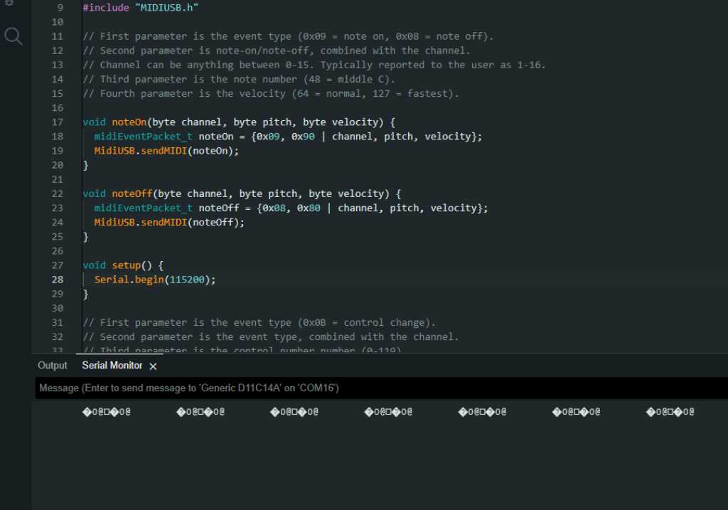
I had my SAMD11C14 programmed with the example above. On Macbook this worked fine. On Windows my serial data output was this:
And no USB MIDI device to be found. I went searching for an answer on Google and I’m not the only one with this issue:
After extended trouble shooting and device manager fiddling, It turned out that Windows was auto installing the wrong (or partially wrong) drivers that made the native port not be recognised as a USB device.
And SAM21 as a USB HID device has driver issues too: here and here
To be able to get some more insights into windows USB stuff, I downloaded Nirsoft USBDeview.
And indeed my SAMD only appeared as serial device. I tried reinstalling some device drivers and rebooting windows (why not), but that didn’t quite work. Until I decided to had a better look in Arduino IDE and found the following settings in TOOLS -> USB-CONFIG:
- CDC_ONLY (default)
- CDC_HID
- WITH_CDC
- HID_ONLY
- WITHOUT_CDC
- USB_DISABLED
CDC means Communication Device Class. So a serial port for example. Interestingly, this class ONLY is set by default. I changed this setting to WITH_CDC and all of a sudden, my SAMD was detected both as a serial port as well as an USB Audio Device (meaning capable to do MIDI). And it actually worked!
What I still don’t get is why this isn’t an issue on MacOS. Just on Windows. Well, who cares. Got this done.
Combining Main controller and sensor boards
sensor board V6 is the first firmware version that I used to start integrating a fully assembled sensor board with the main controller. This firmware basically flashes all 19 WS2812B LED’s and outputs the measured sensorvalue to the serial monitor. It also sends hit values to the main controller.
I updated the order of the sensors in this firmware, so that it reflects the physical order of the sensors.
Find the code for the sensormodule here: sensormodule_FW_v6
Find the code for the mainmodule here: mainmodule_FW_v1
MIDI Buffering
Buffering can be important especially if there’s more to send or more to read than the microcontroller can deal with at the moment. Reason for this is that it can cause latency, which I want to prevent as much as possible.
The Arduino MIDIUSB library that I use has a build-in READ buffer. See this link to the MIDIUSB.h file, line 49. It references to EPX_SIZE. This is because I’m using a SAMD and so the defined(ARDUINO_ARCH_SAM) is TRUE.
EPX_SIZE is not defined in the MIDIUSB library. That is because it’s based on the PluggableUSB API. So the buffer size is actually defined in the USBAPI.h file. So the read buffer size is #define EPX_SIZE 64. That is in bytes.
There appears to be no send buffer. The MIDIUSB library only provides a sendMIDI() function that “sends a single USB message” and a flush() function that “waits for all messages to actually be send”. This is not very descriptive but according to https://www.arduino.cc/reference/en/libraries/midiusb/midiusb.flush/
This function forces the USB layer to send the data immediately. Since the USB bus is not realtime, a `sendMIDI()` doesn’t guarantee the data to be sent with the correct timing unless immediately followed by a `flush()`
And indeed USB communication is threated differently from serial communication. In serial communication there is a write buffer and a Serial.availableforwrite. If the write buffer is full (for example you push more data into it than the UART can send given its baudrate), the Serial.write command will block. You can check availableforwrite() if there’s space left in the buffer and deal with it so it doesn’t block (blocking is bad, it stalls the microcontroller for a moment).
In USB, data is send in packets and the USB controller hardware of the microcontroller takes care of managing these packets. There appears to be a TXC flag (Transmit complete interrupt flag, see SAMD21 datasheet 26.6.2.5) and a DRE flag (Data Register Empty flag) that indicate that the USB endpoint is ready to send more data.
So hopefully this is all implemented correctly in the SAMD core and I don’t have to mess around with this.
What I should do though is add a flush() command immediately after a sendMIDI() command as to guarantee that the midi data is send right away.
Communication protocol
The main and peripheral microcontrollers are communicating using I2C. I will have to define and program a communication protocol, so they understand the data that they’re going to send back and forth. I came up with the following:
** I2C Marimbatron protocol:
** C = type: Command to execute - followed by character that defines what command
** S = type: Set - followed by character that defines what to set
             (sometimes followed by uint_8 to indicate sensor number)
** G = type: Get - followed by character that defines what to get
            (sometimes followed by uint_8 to indicate sensor number)

** main sends chars XR -> peripheral will reset (NVIC_SystemReset())
** main sends chars XA -> peripheral will do auto-threshold procedure
** main sends chars XS -> peripheral will stop sensor measurements.
            All detected hits that we're not sent yet will be flushed.

** main sends chars GH -> peripheral is set into Get sensor Hit mode ->
        on datarequest (3 bytes) it sends sensorvalue of sensor with
        hit = true (or 255,0,0 if no hit)
        All detected hits that we're not sent yet will be flushed.
** main sends chars GC followed by byte sensornumber ->
        peripheral is set into Get Continuous actual value -> on datarequest
        (3 bytes) it sends sensorvalue of [sensornumber]
        and on next datarequest it sends sensorvalue of sensor with
        hit = true (or 255,0,0 if no hit)
        on next datarequest back to sensorvalue of [sensornumber], etc.
** main sends chars GA followed by byte sensornumber ->
        peripheral set into Get single Actual values mode ->
        on datarequest (2 bytes) it sends actual sensorvalue of [sensornumber].
** main sends chars GT followed by byte sensornumber ->
        peripheral set to Get Threshold mode ->
        on datarequest (2 bytes) it sends current threshold value
        of [sensornumber].
** main sends chars GX followed by byte sensornumber ->
        peripheral set to Maximum mode ->
        on datarequest (2 bytes) it sends current maximum value of
         [sensornumber].
** main sends chars GM -> peripheral set into Masktime mode ->
        on datarequest it sends the current masktime.
** main sends chars GN -> peripheral set into Scantime mode ->
        on datarequest it sends the current scantime.

** main sends chars ST followed by byte sensornumber followed by uint_16 value ->
        peripheral sets threshold of sensor [sensornumber] to [value].
** main sends chars SX followed by byte sensornumber followed by uint_16 value ->
        peripheral sets maximum of sensor [sensornumber] to [value].
** main sends chars SM followed by byte sensornumber followed by uint_32 value ->
        peripheral sets Masktime of sensor [sensornumber] to [value].
** main sends chars SN followed by byte sensornumber followed by uint_32 value ->
        peripheral sets Scantime of sensor [sensornumber] to [value].
** main sends chars SL followed by byte layoutnumber ->
        peripheral sets layout to [value].
** main sends chars SC followed by byte sensornumber followed by
        3 bytes RGB value -> peripheral sets color of
        sensor [sensornumber] to RGB [value].
This communication protocol is (almost fully) implemented and working in this source code:
the sensormodule here: sensormodule_FW_v7
the mainmodule here: mainmodule_FW_v2
Implementing UI
The menu on the UI will be made using ArduinoMenu https://github.com/neu-rah/ArduinoMenu library. The reason for choosing this menu library over the other available ones (or making my own) is that it is designed as a non blocking polling system. That should work great in my code because I’ve set it up in a polling way (meaning no commands on interrupt but all based on 100 microsecond counters).
This library can work with a multitude of inputs and outputs, so works fine with my buttons and it works with https://github.com/adafruit/Adafruit-GFX-Library. The round LCD https://www.waveshare.com/wiki/1.28inch_LCD_Module has a GC9A01 controller. The Adafruit GFX library has a driver for that: https://github.com/adafruit/Adafruit_GC9A01A. This controller is by the way also supported by https://github.com/Bodmer/TFT_eSPI which can also be used with the AduinoMenu library. So lots to choose.
I installed all three items using Arduino IDE library manager. Just search and hit install. Next I tried implementing the LCD spiral that I made in output-devices week. That was done on a SAMD11C14 and now I’ll use the SAMD21E. So bit of fiddling around and it should work fine.
But…
After hours and hours (12+) of trial and error I finally got a spiral on my screen. That should’ve been much easier, but disaster:

Somethings wrong with my LCD! As soon as I wiggle the wires, it drops out. And I have no replacement unit… So I’m stuck without screen.
Fortunately ArduinoMenu library is here to rescue me. As mentioned it works with a multitude of output devices. Serial UART is one of it. So I made a menu that can be seen in the serial monitor :-) To control it you’d still use the buttons of the Marimbatron. And that works fine for now.

the sensormodule, including non-volatile flash storage of settings is here: sensormodule_FW_v7 the mainmodule with the ArduinoMenu UI and buttoncontrol is here: mainmodule_FW_v3