Leg
Also called Computer Numerical Control (CNC) is a manufacturing method that use preprogrammed software to
control the movement and speeds of the tools.
There are a lot of different types of CNC like routers, drills, water jets, etc.
This works thanks of a G-code or M-code this two contains the instructions and parameters of the tools. First
you have to create a drawing CAD for then, thanks to a post processor generate the code.
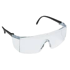
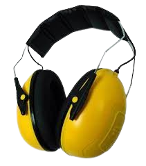
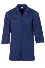
Whenever you use a machine there is always a risk, so a way of preventing them is using the appropiate equipment. Also knowing where are the fire extinguisher, fire alarm and school nursing.
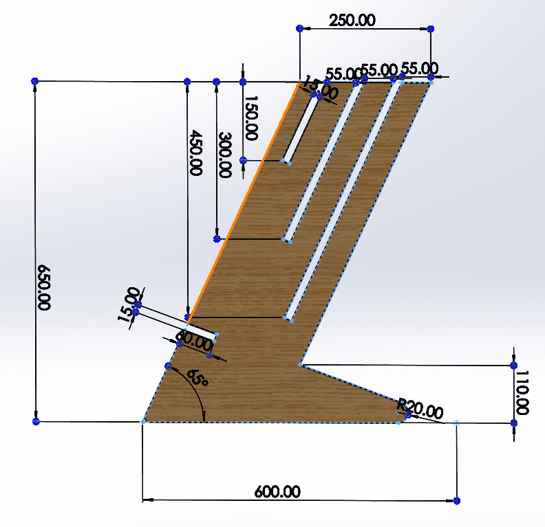
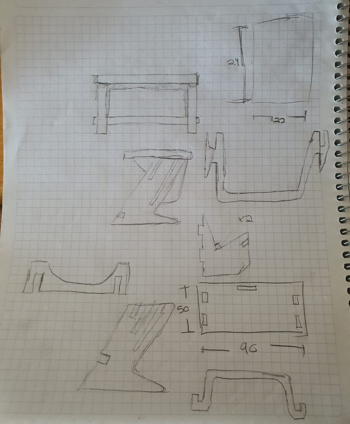
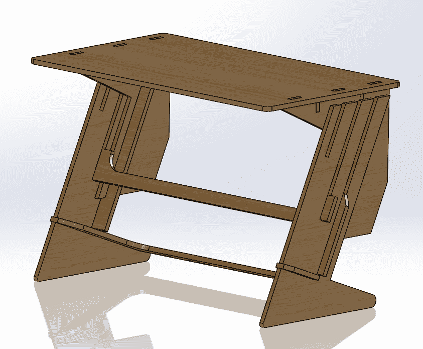
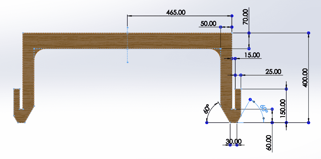
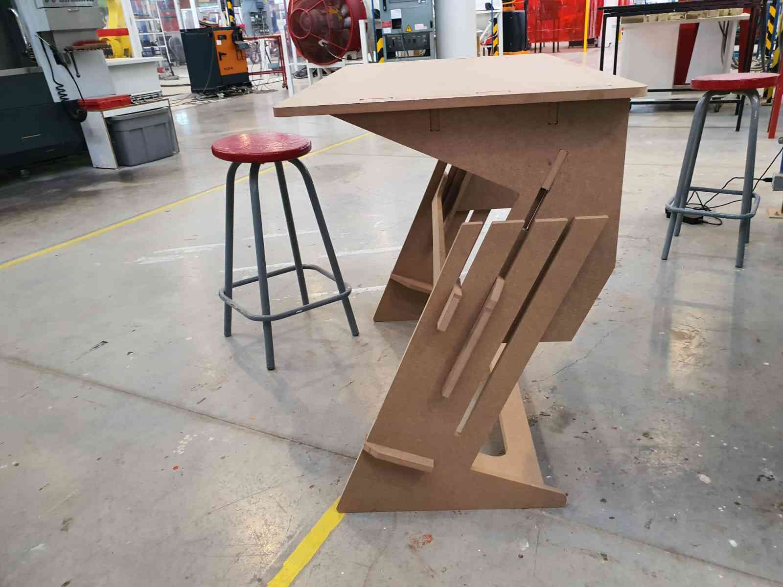
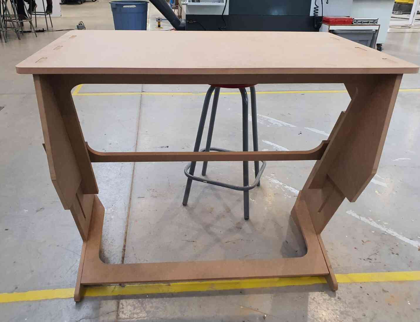
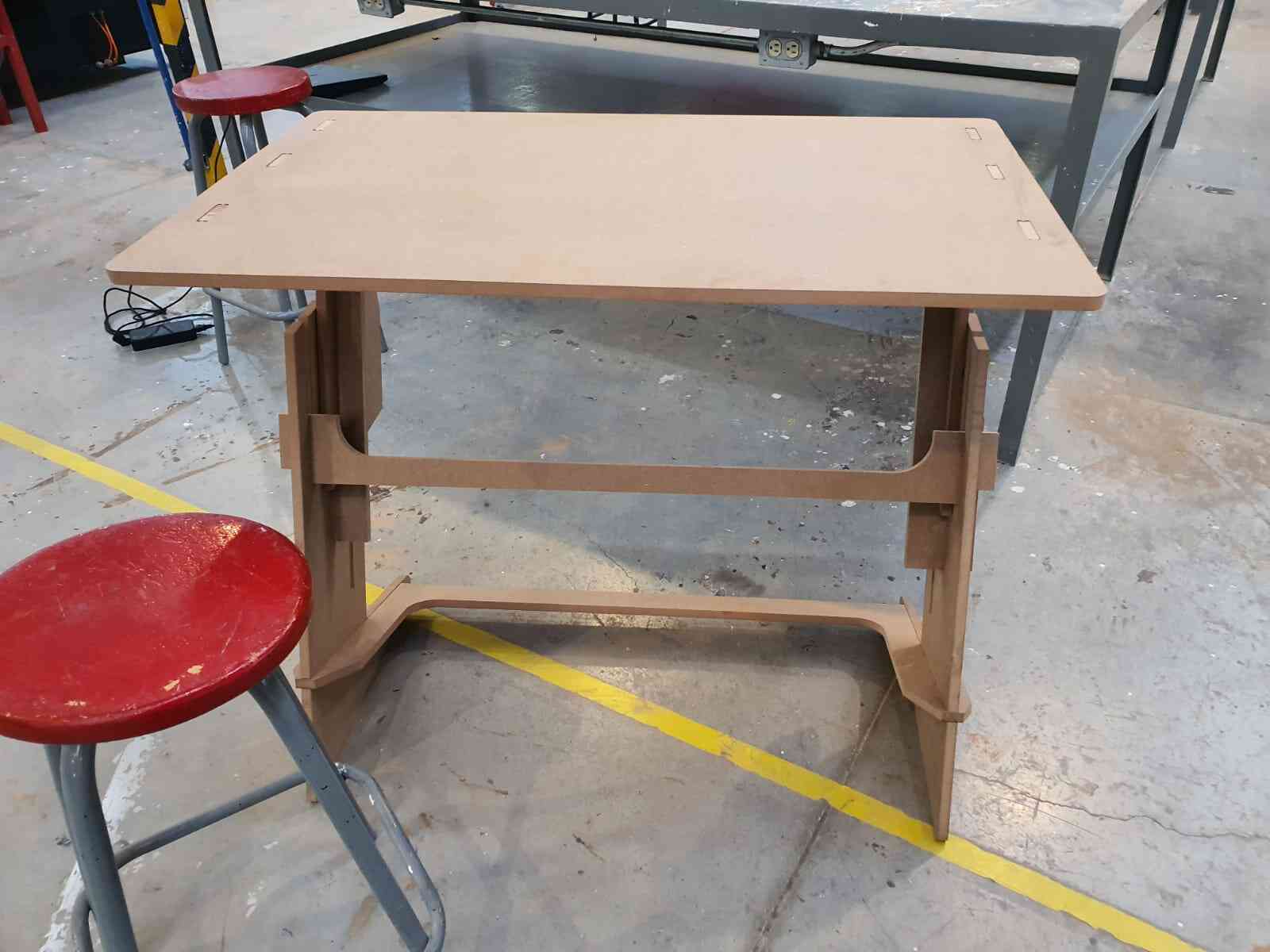
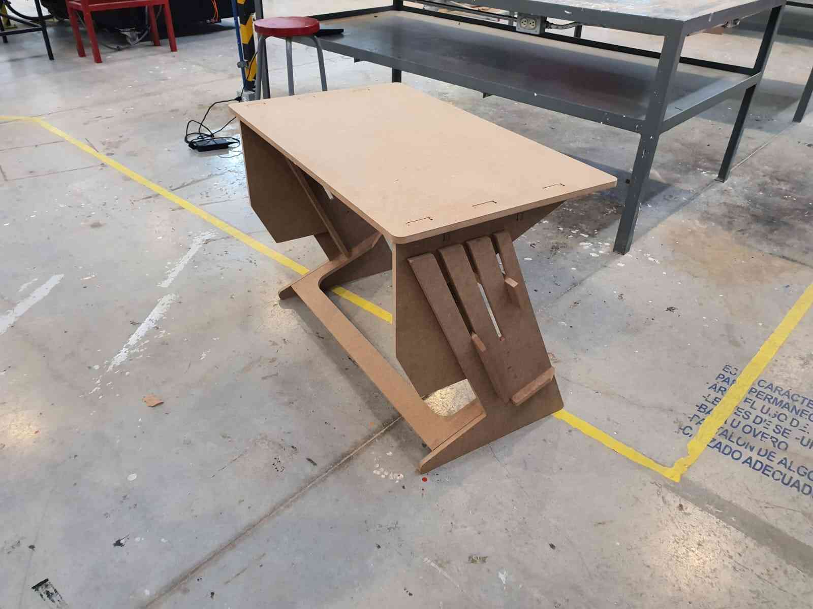
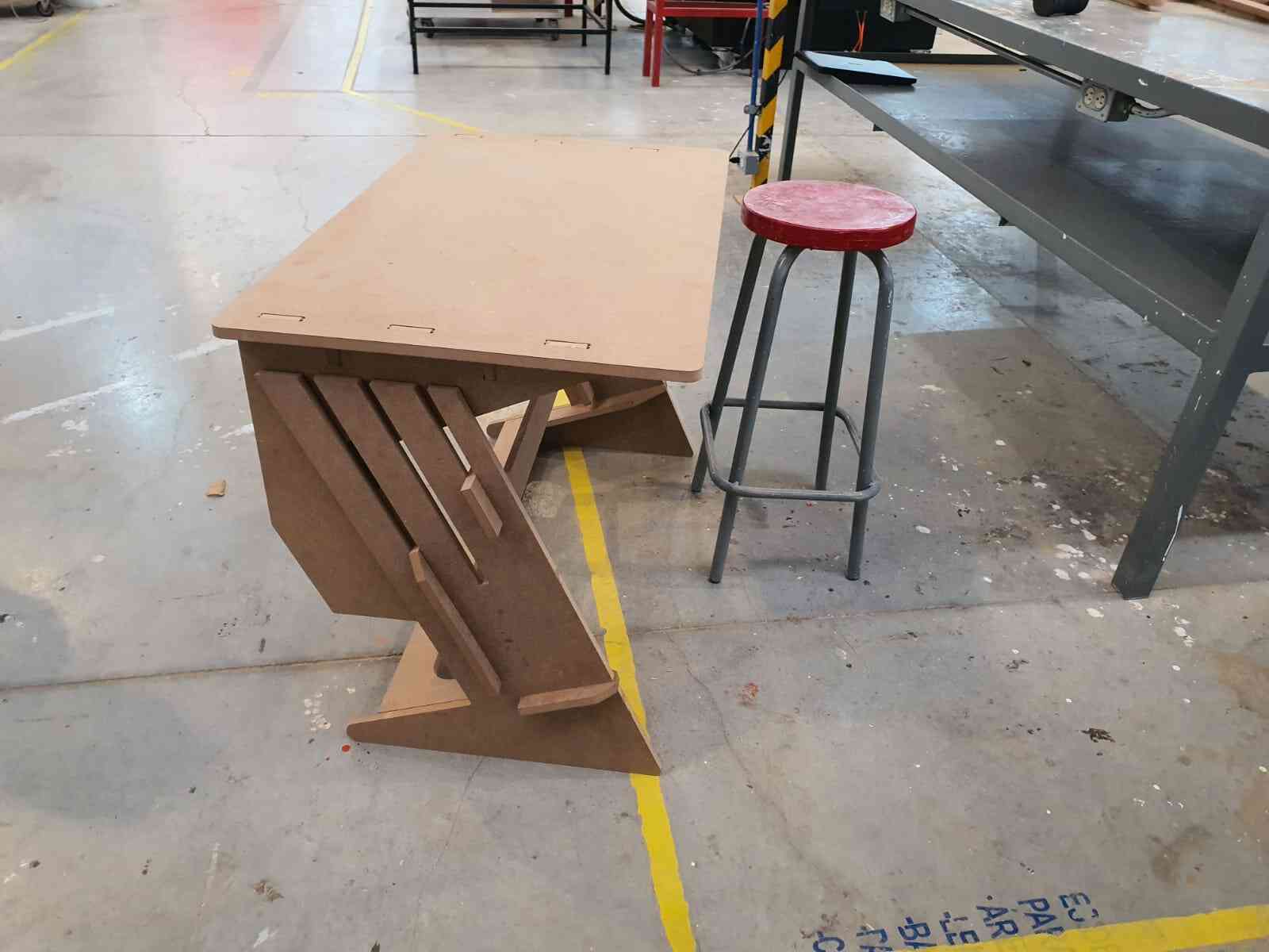
For this week assignments I will be making a desk that can adjust it height in 3 different levels (chair, workshop bench and standing).
After investigating different designs on Pinteres I found something to recreate and modify.
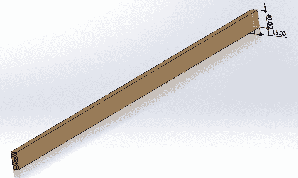
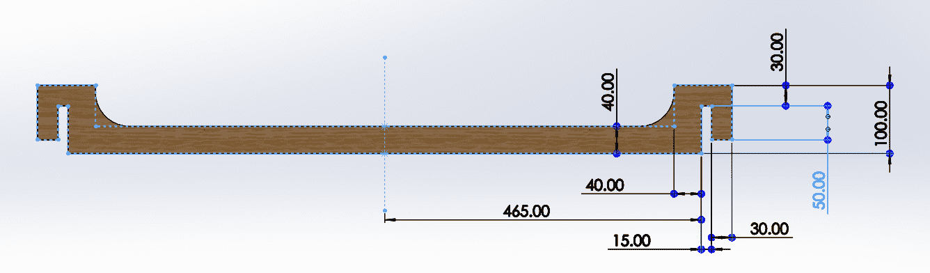
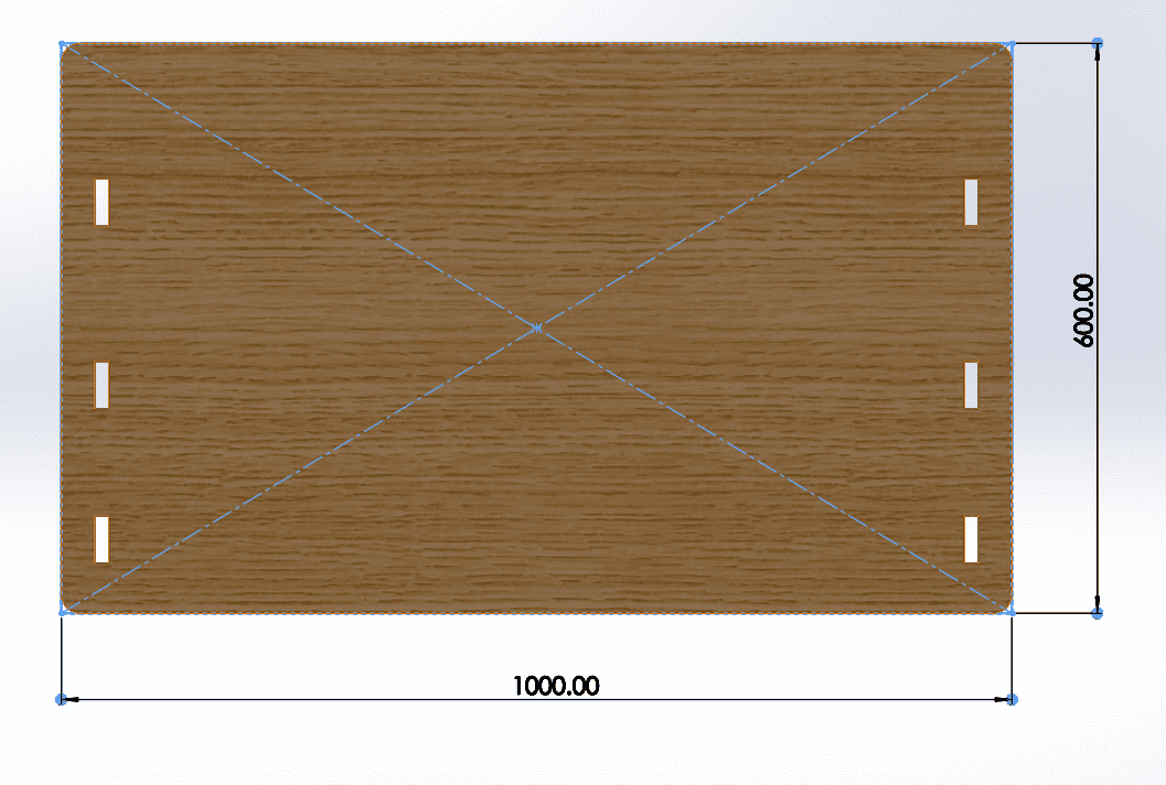
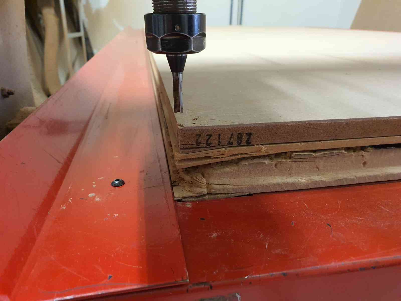
We will use MDF of 15mm, this is important to consider the dimencions of the slots and the stress of the parts they will take.
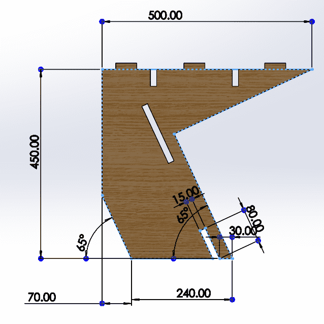
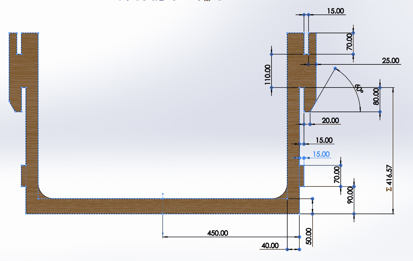
First I made a sketch of the parts to give me an idea of the dimensions of the mdf and with a flexometer meassure other Desks
to find the different heights.
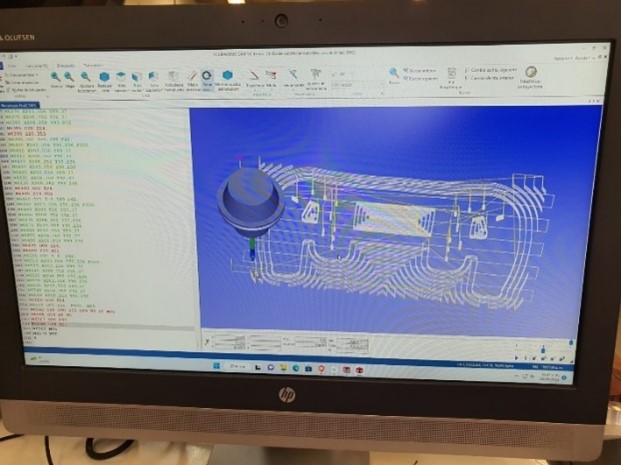
For the procces I used the software VCarve to generate the code and modify all the needed parameters.
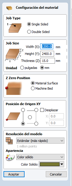
Is the first thing it appears when creating a new file. Here you can change the dimensions of the material you are cutting in mm or in.
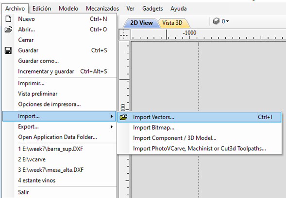
For adding the files you have to import them as Vectors (they will be open).
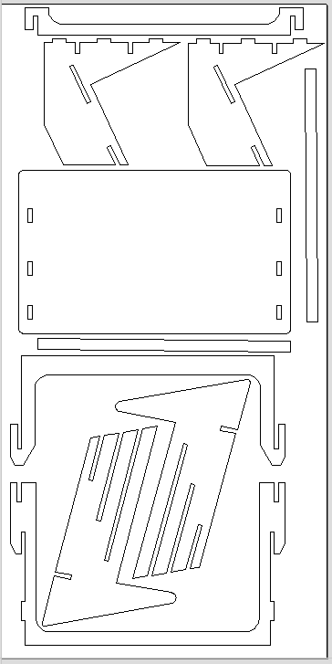
After adding all my parts I order them to fit in the material.
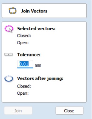
It is important to join the vector to be a continuous contour. For this, select all the parts and click on join vector. There you can see how many are open and close.
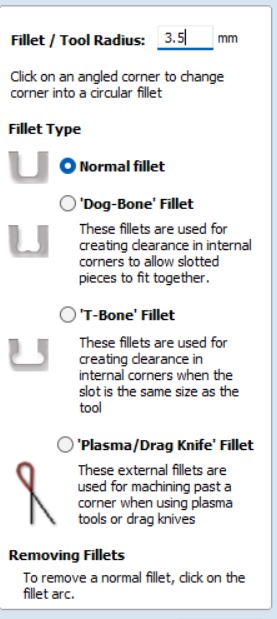
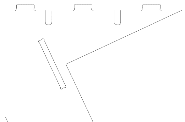
Like we want to be all pressed fit and the tool is circular, we can't make 90° turns in the holes, so adding a fillet help our parts to fit right in. There are diferent types of fillet, Dog-bone and T-bone, select one and add it to all the inside corners.
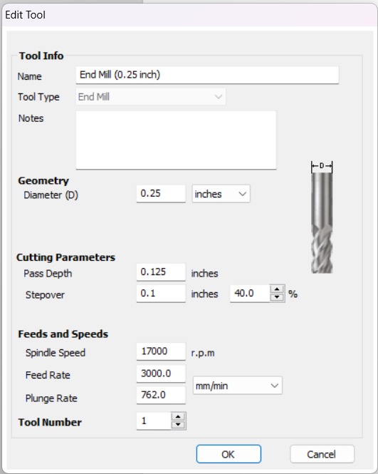
Depending on the material you got, it is important to change all the tool parametrs. Acording to the table on the group site, change the spindle speed, feed rate, number of passes, etc.
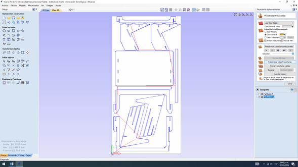
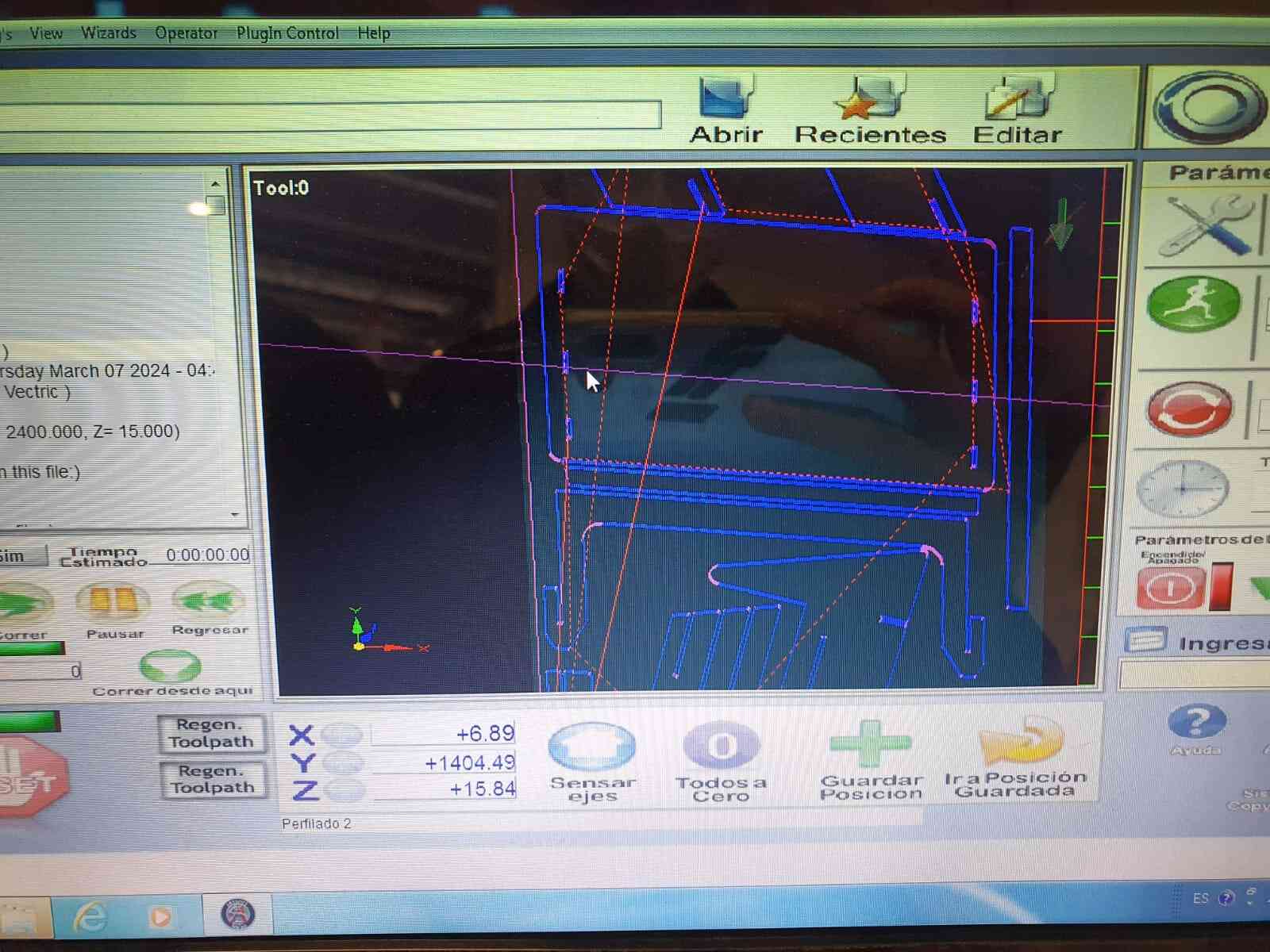
After adding everything using the simulation can give a great reference of what the machine will performs in case you don't lika a movement you can change it before it is too late.
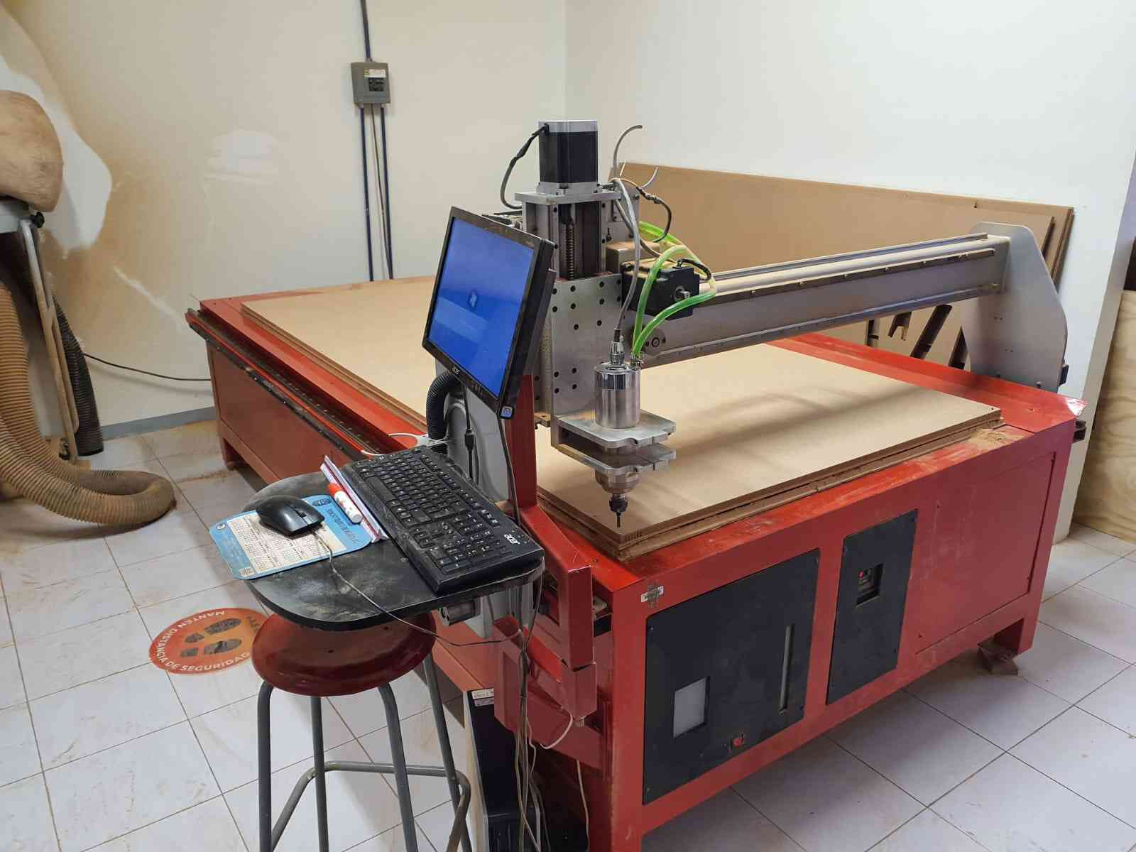
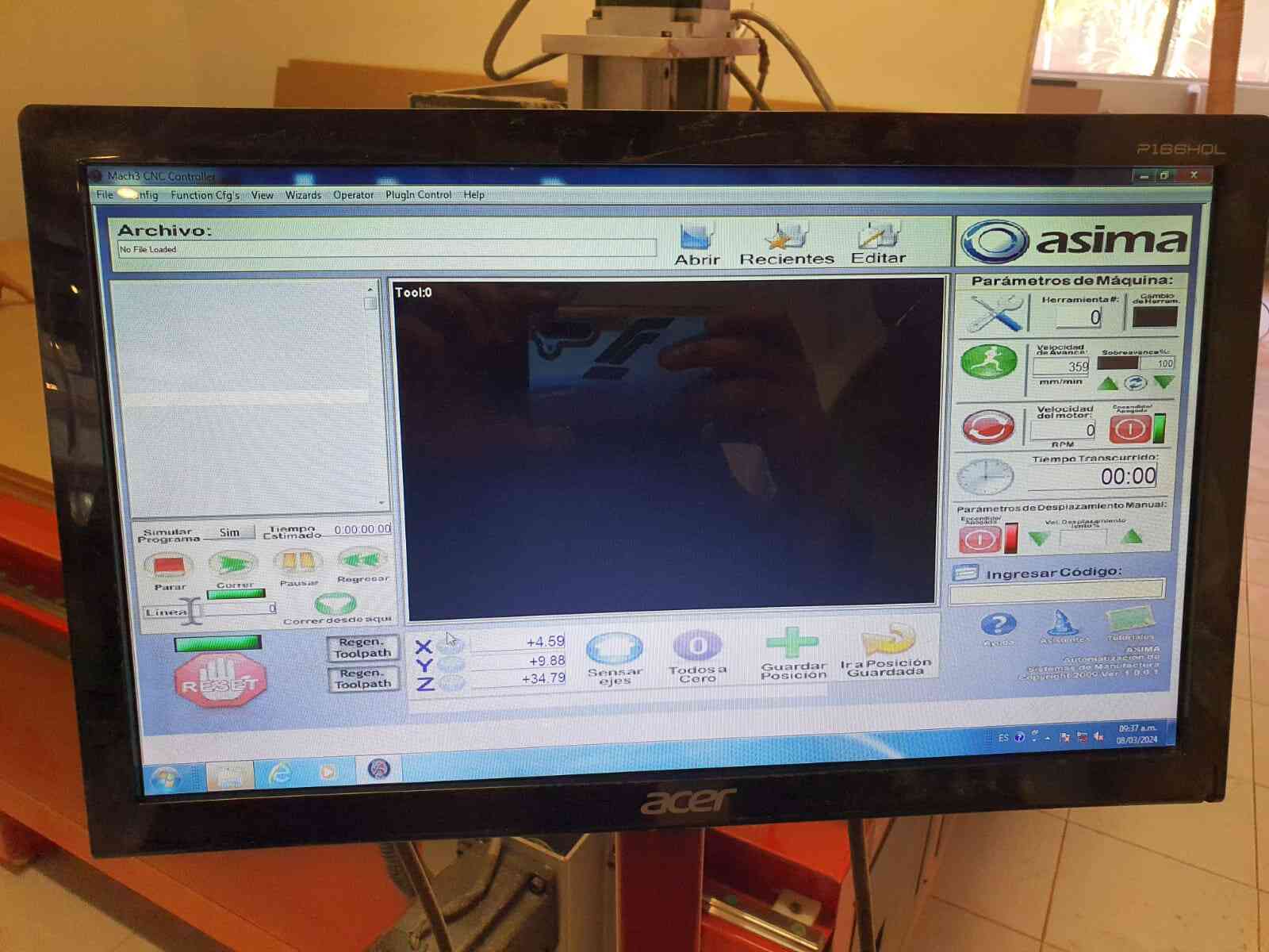
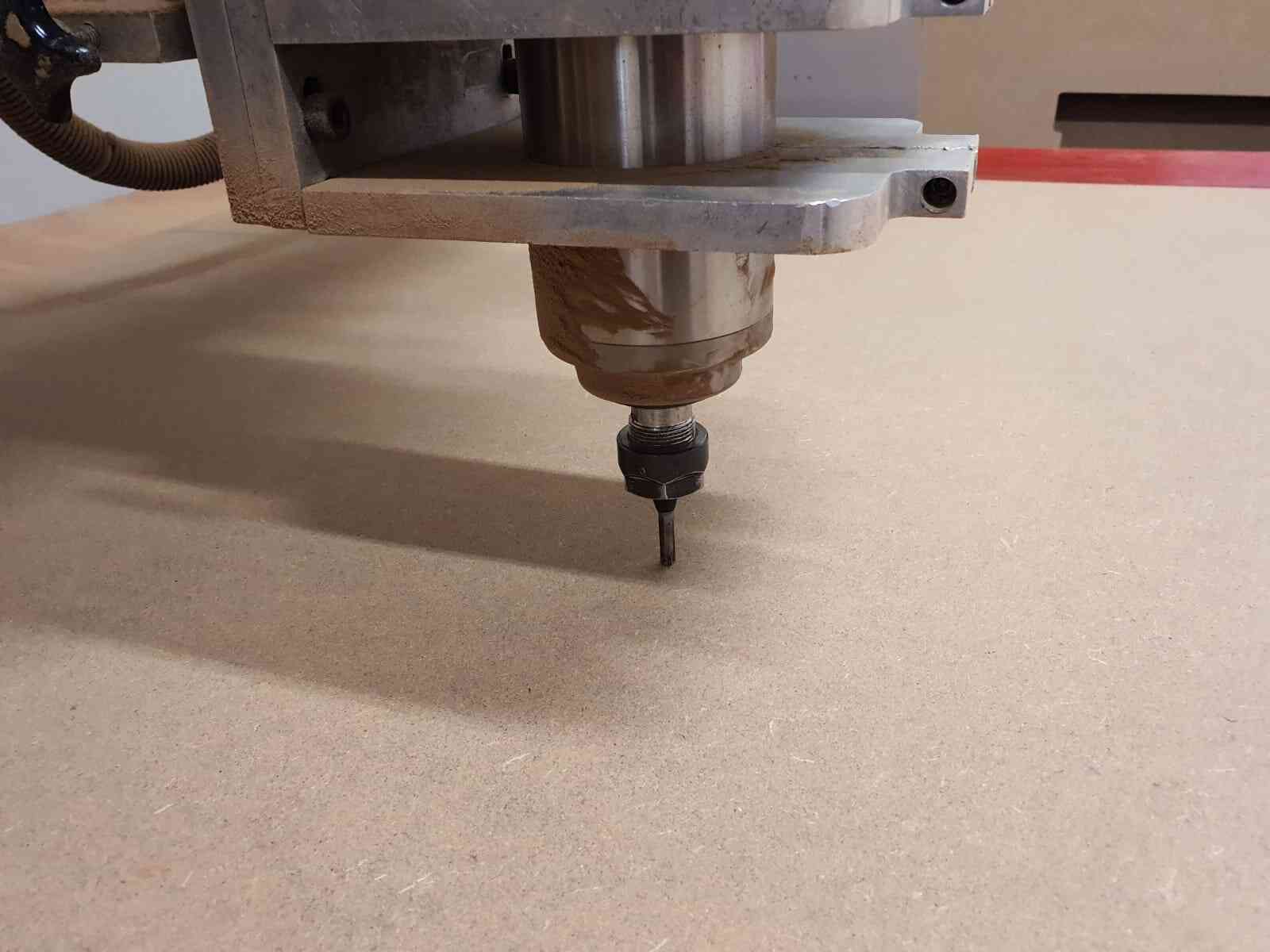
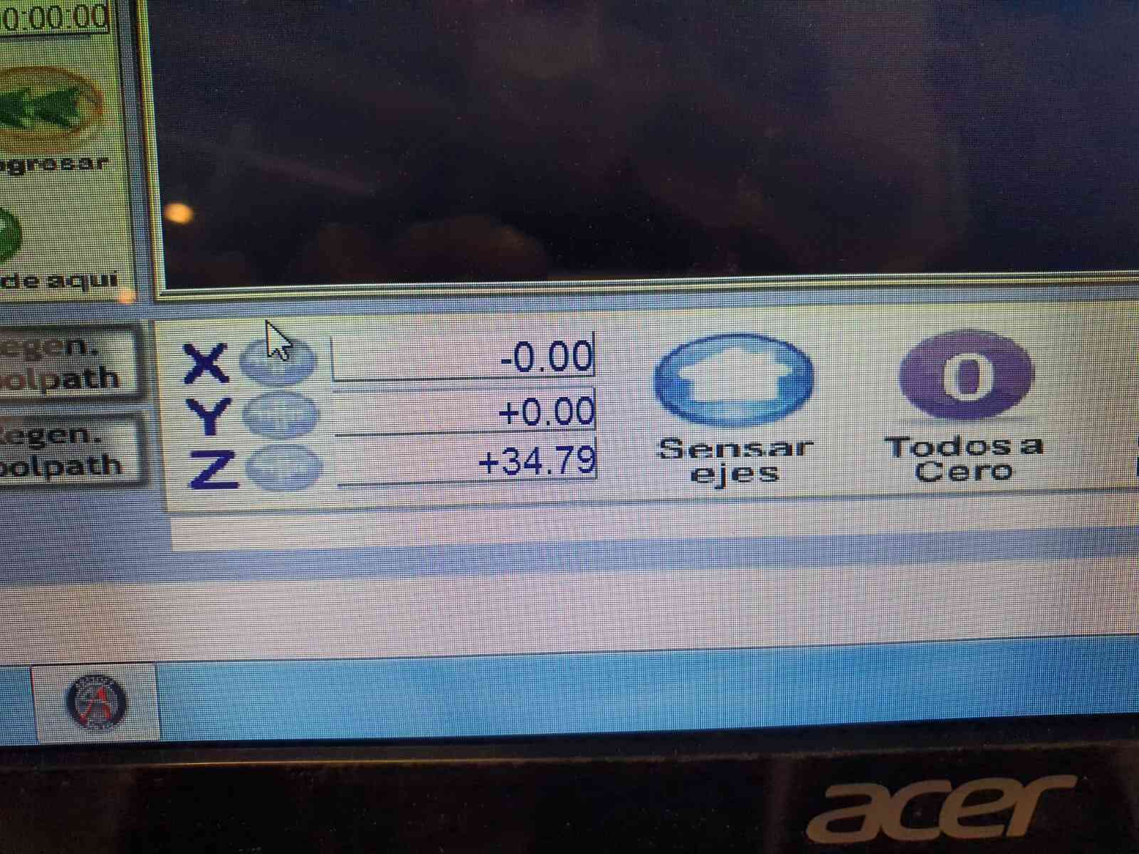
I will be using the Mach router. After having my code in a USB.
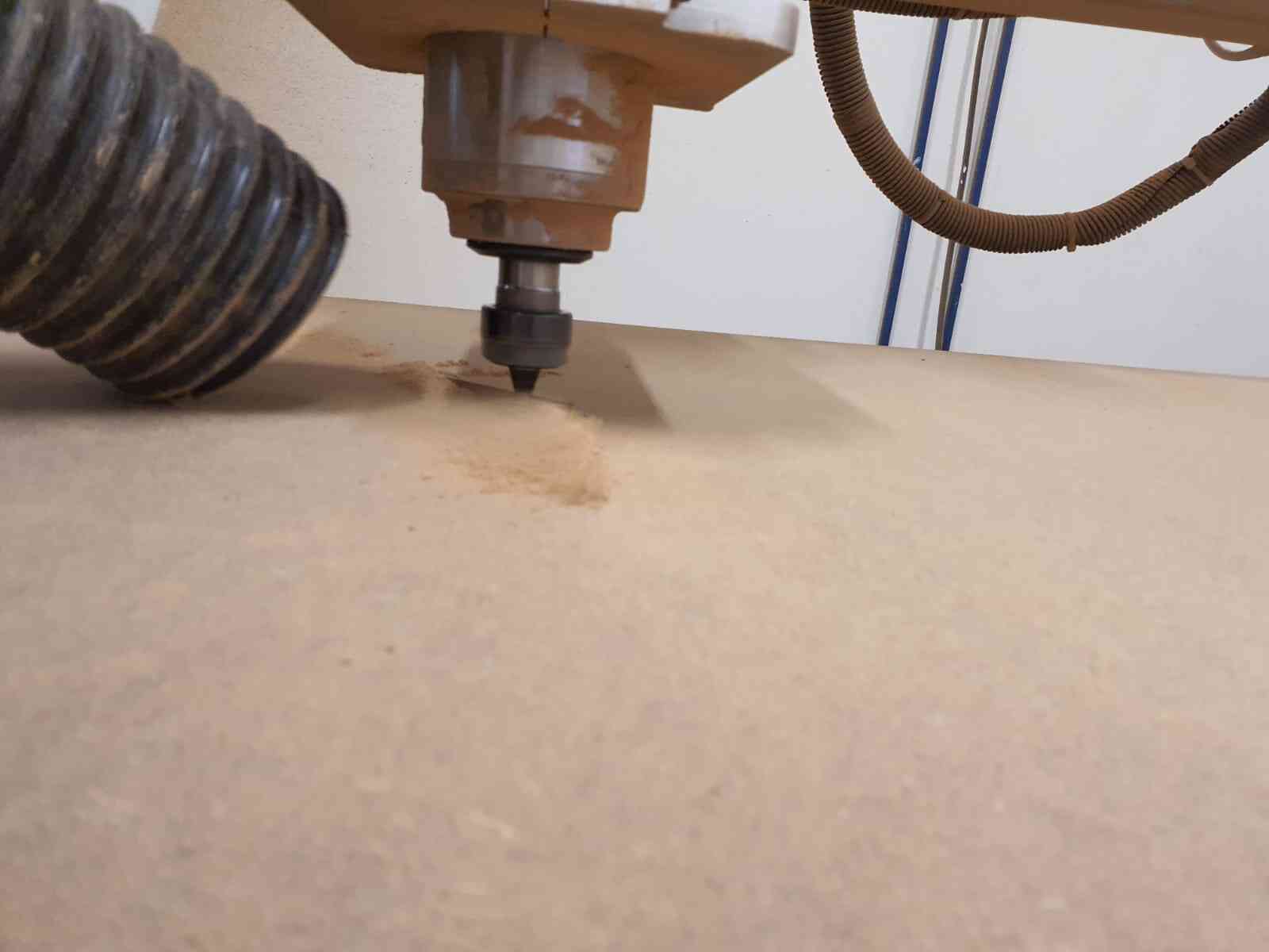
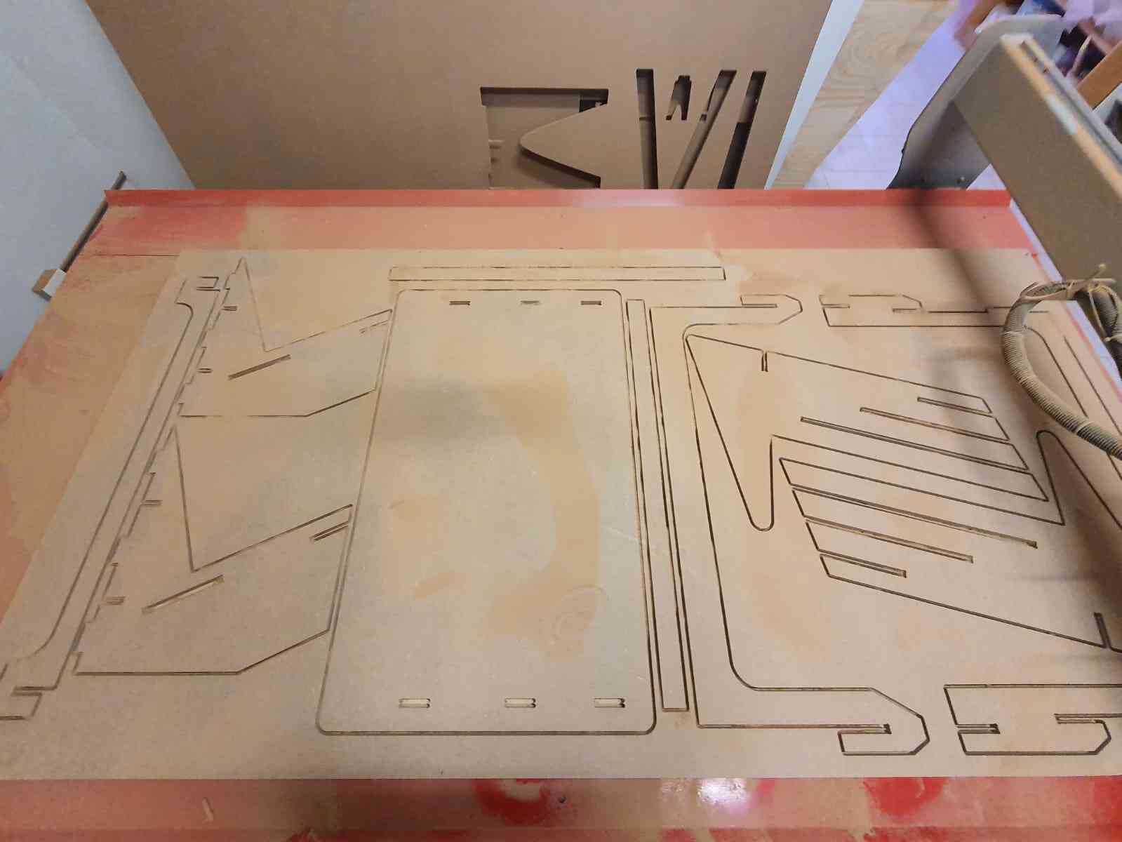
After getting all our parts it is important to remove the tabs that the machine left.
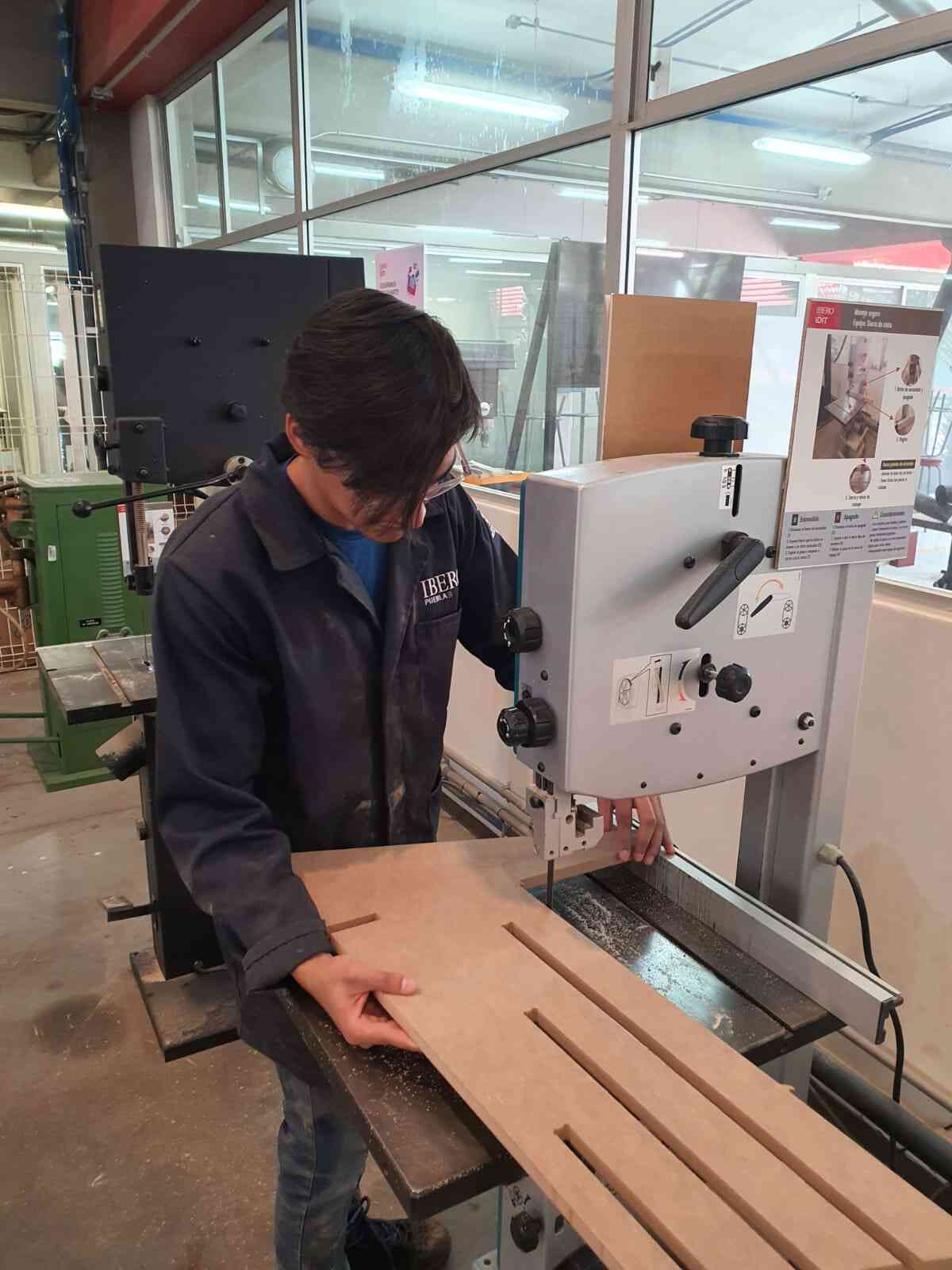
Now that the part are completly clean we can start to assemble the desk.
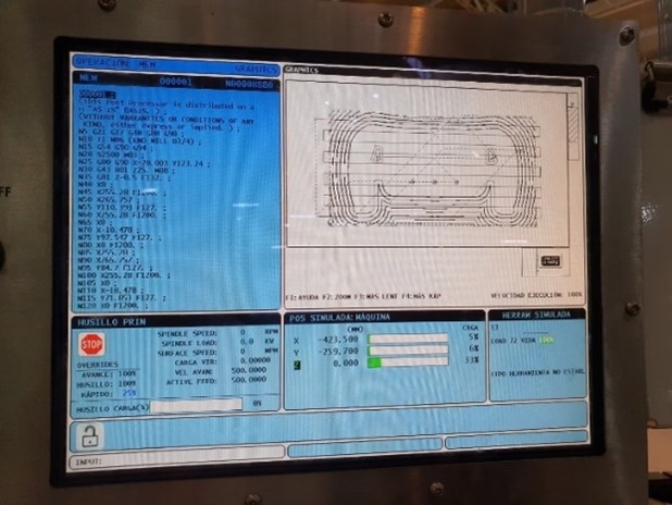
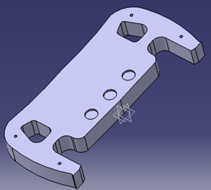
Another machine we have is the HAAS VF1. For making parts in this milling machine fist you have to make
the part design on CAD, after in the same program you select all the milling operations and generate the code.
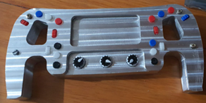
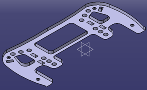
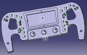
Last semester I made a F1 steering wheel which I decorated using 3D printing parts.
Tools configuration
One of the amazing uses of the machine is the option for changing between tools that are mounted up on a carousel.
You can change by giving it diferent CNC codes. Such as:
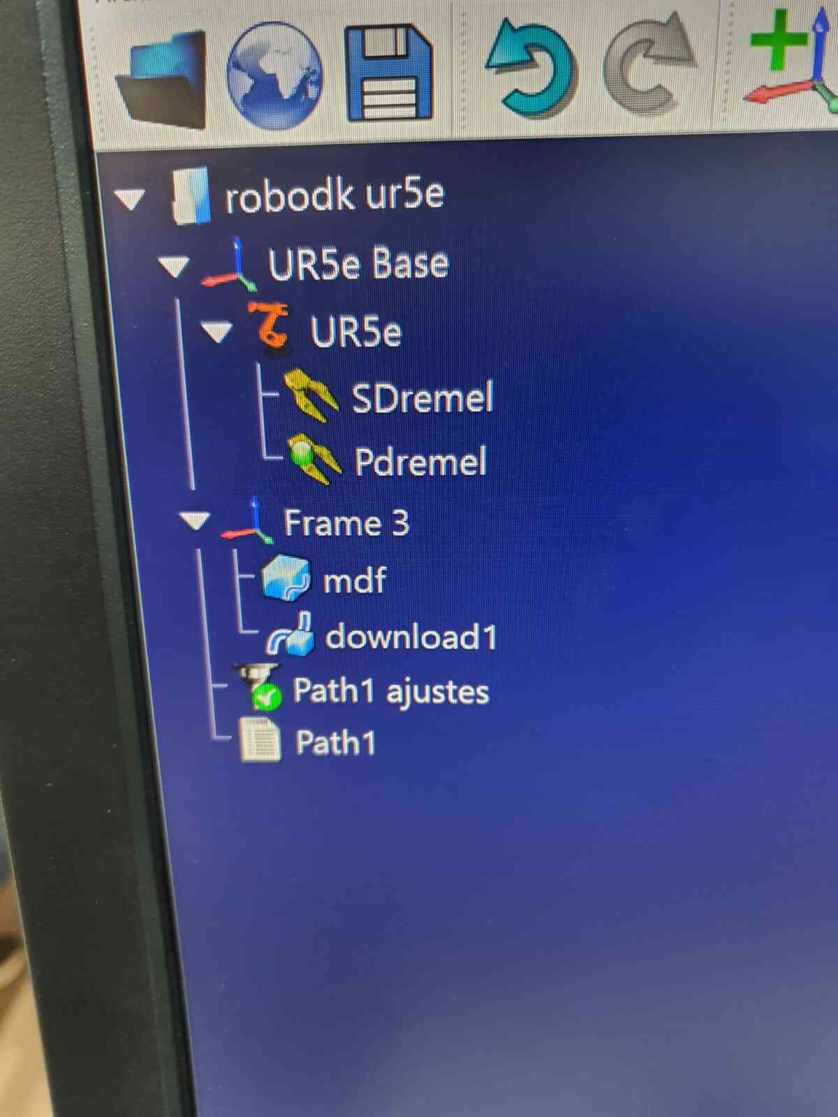
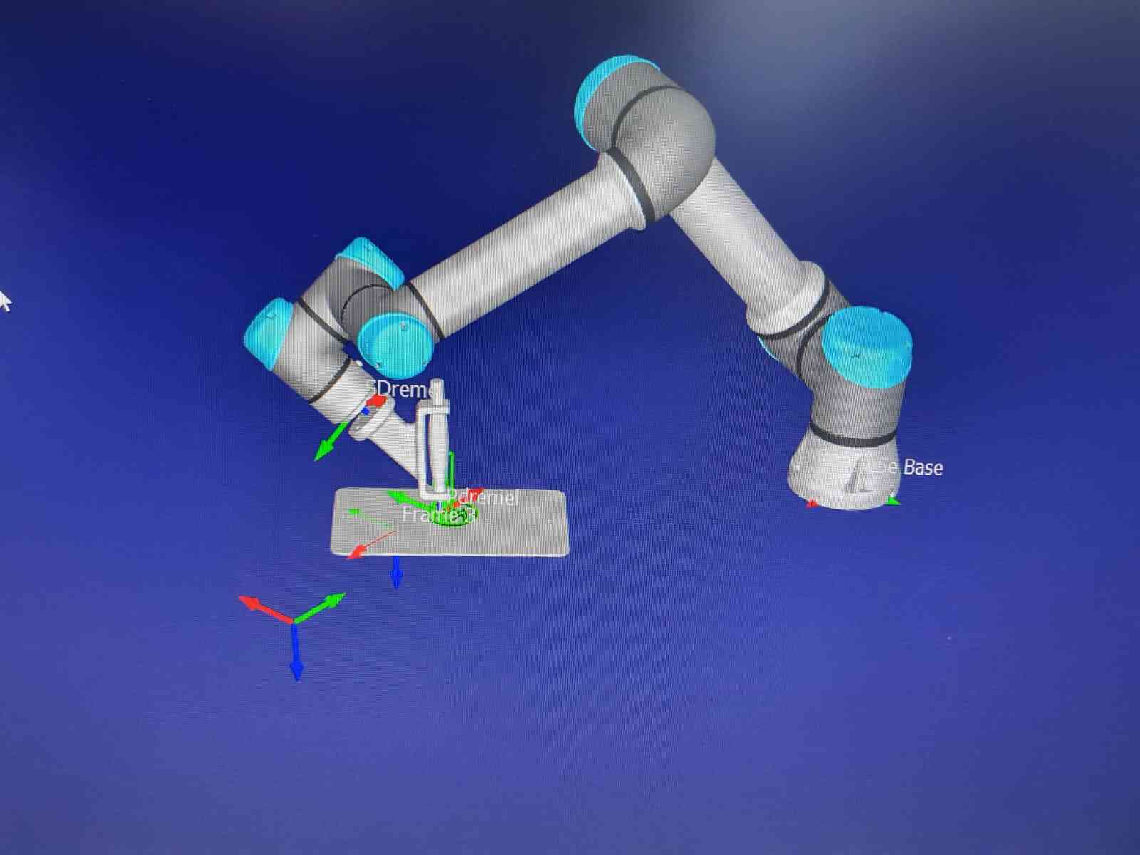
Also adapting a UR robot for engraving and cutting is possible, in this case using RoboDK simulator.
After selecting the tobot, creating a working plane and adding the tool and dxf file, we can create a
code using its post processor.
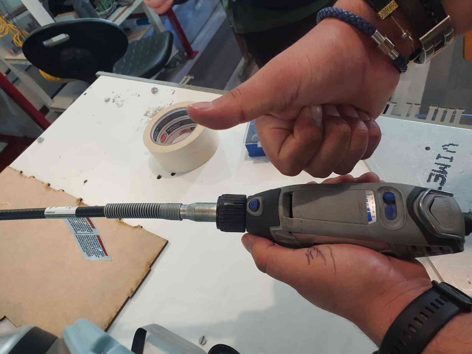
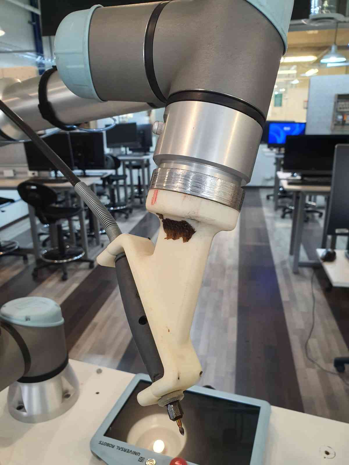
For making the mill we use a dremel and connect it to the engraver.
After calibrating the UR and the mdf material we can start the procces.