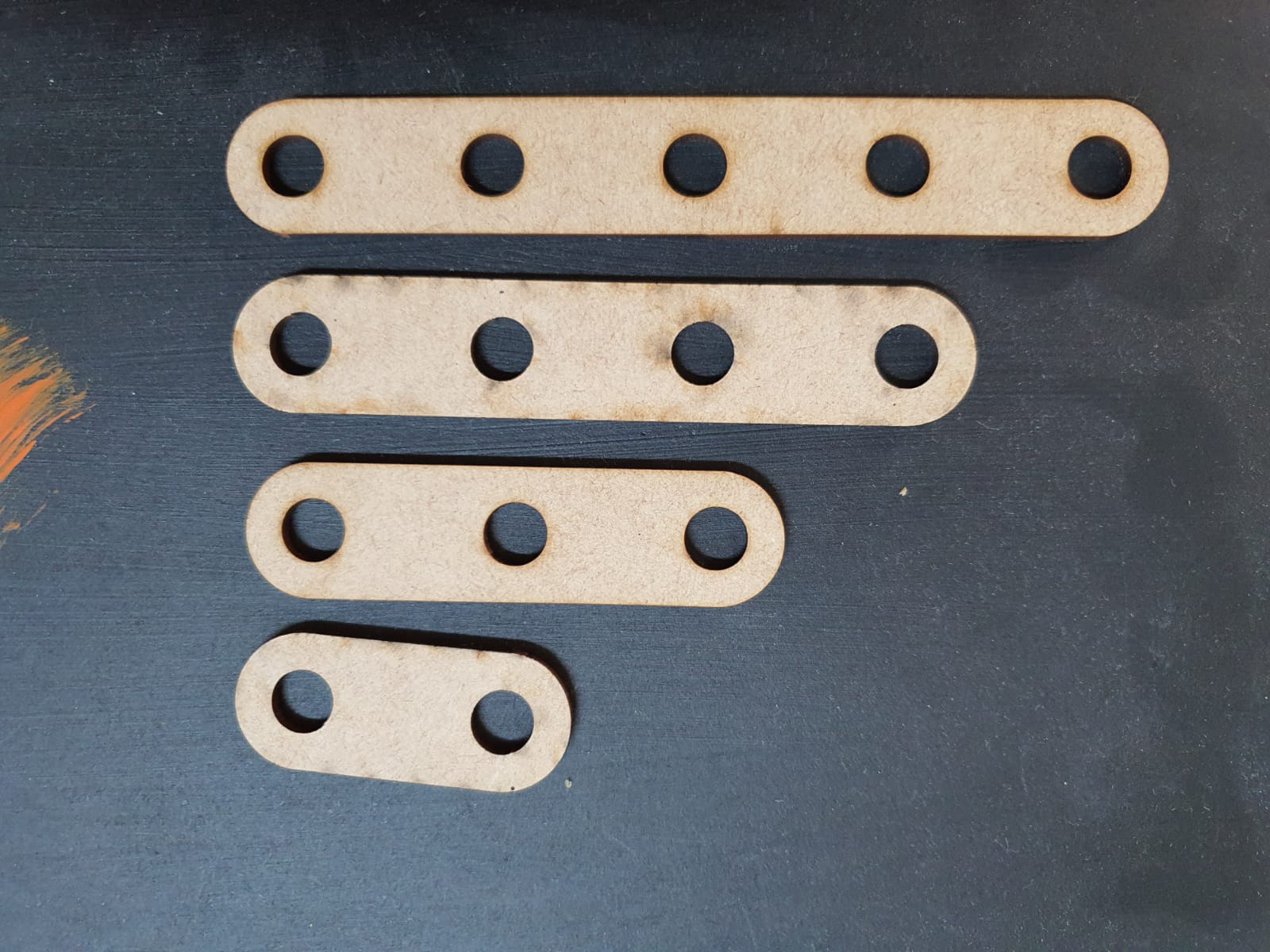
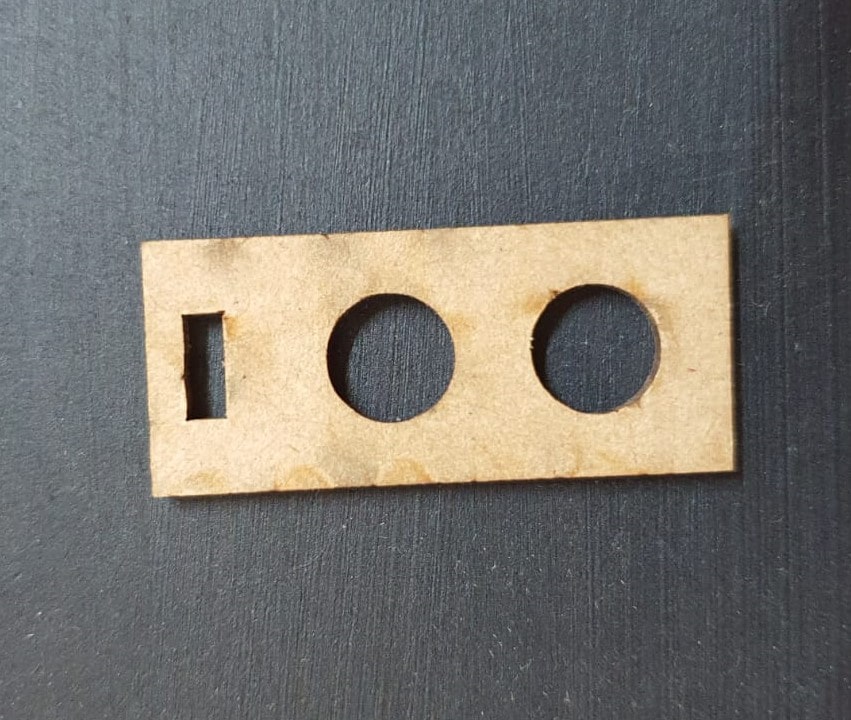
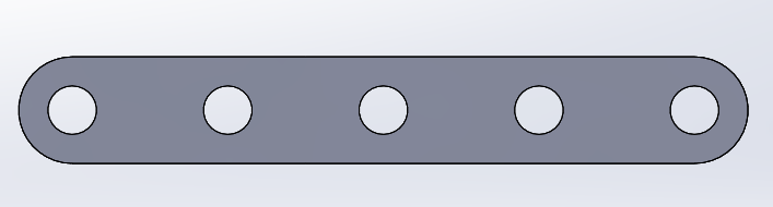
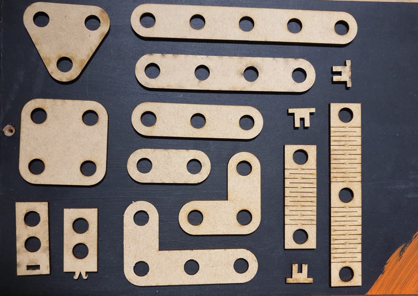
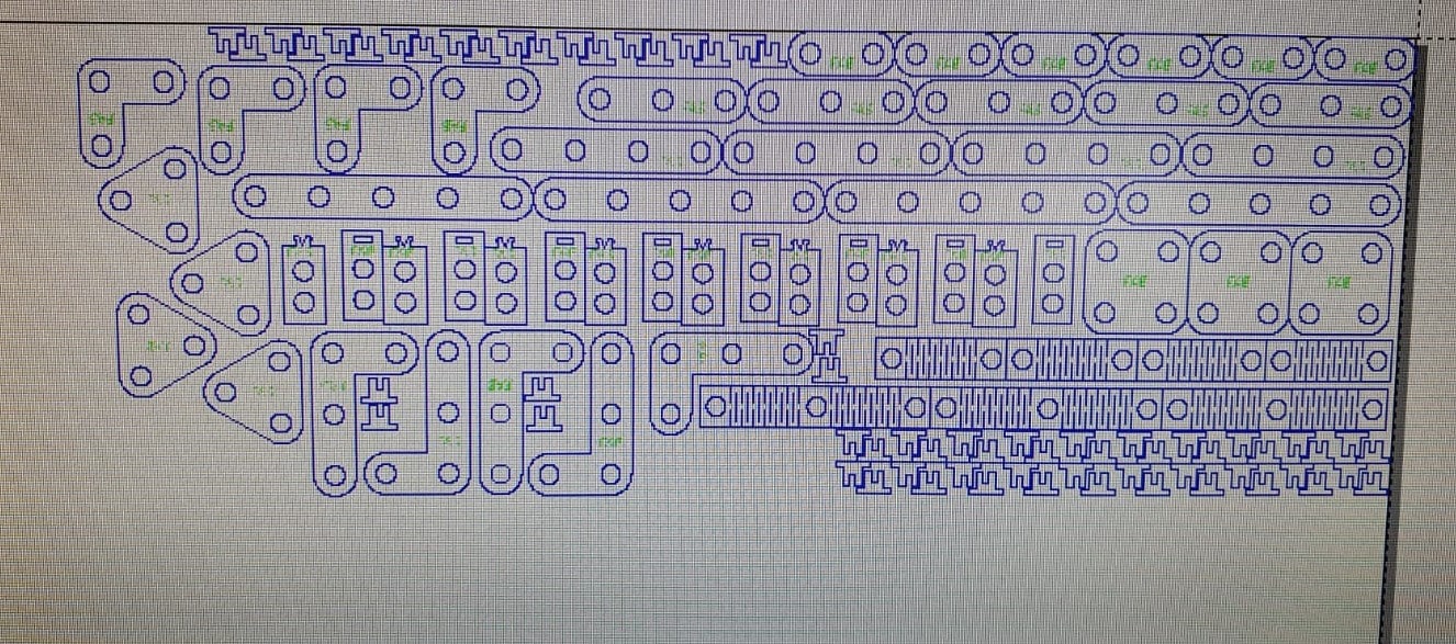
Straight BAR
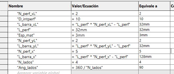
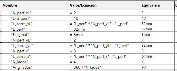
We can have different lengths of the bar by changing just 1 parameter (number of holes).
This week assignement is to design a parametric kit using a CAD software, then cutting it in LASER. Also to create or cut something in the Vinyl machine.
Fortunately this isn't my first time using the LASER MAchine so this helped me a lot in using it for the assignment.
LASER Machine
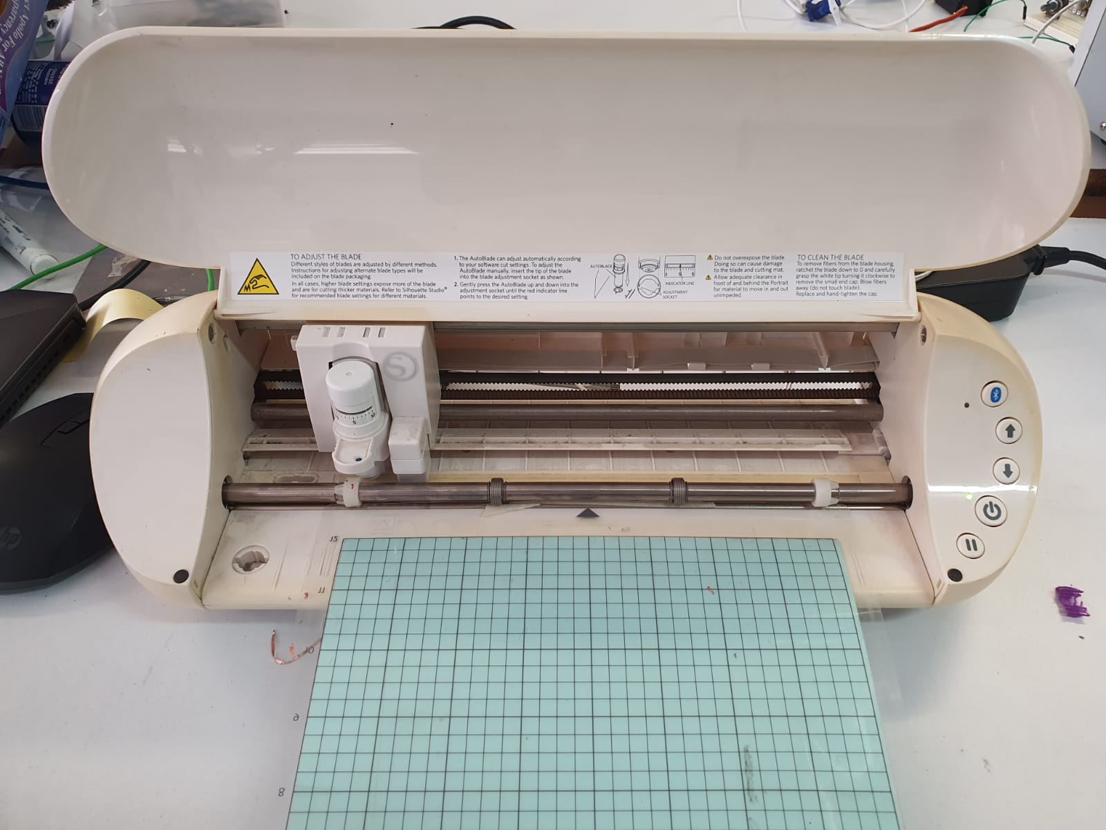
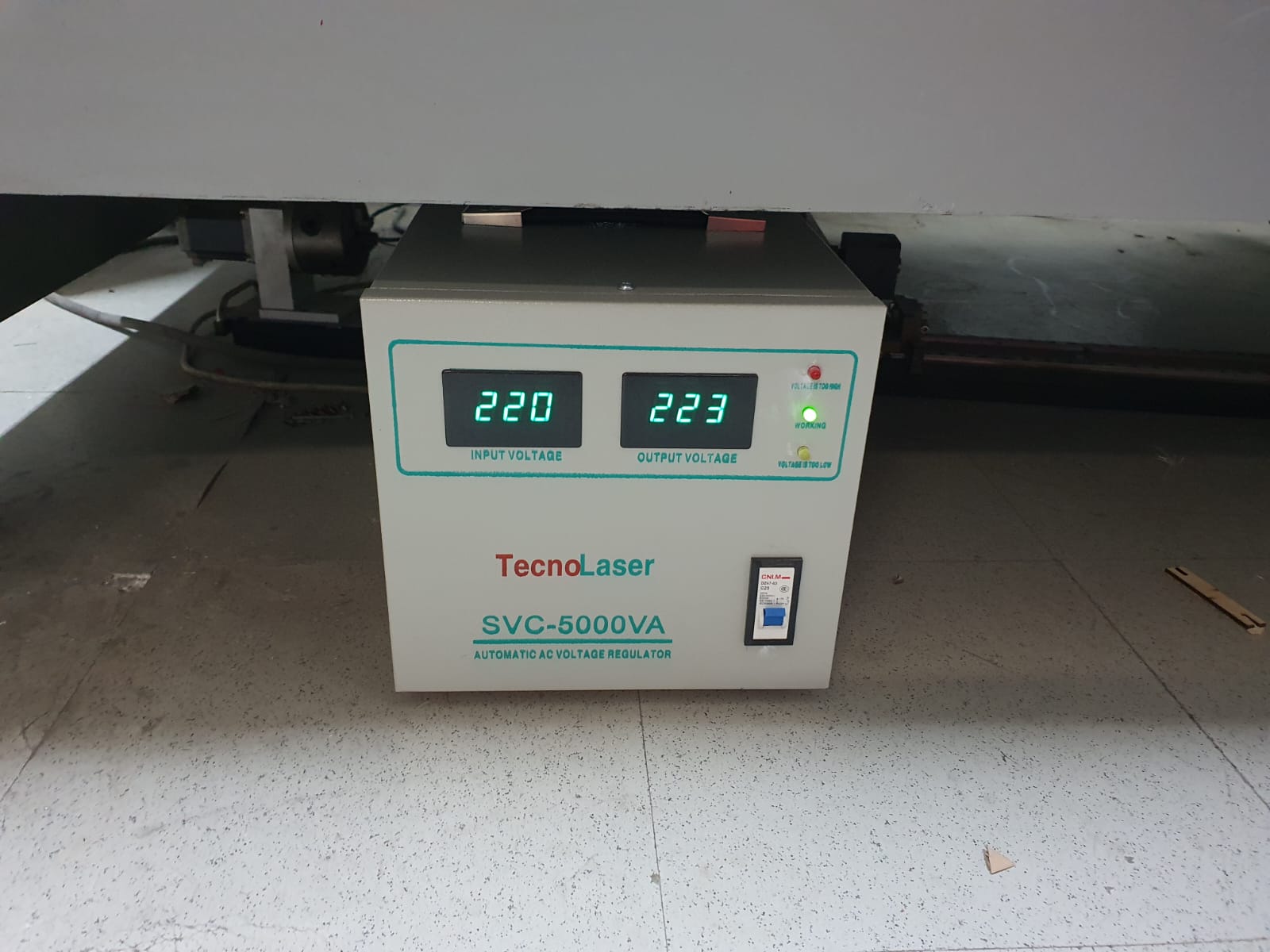
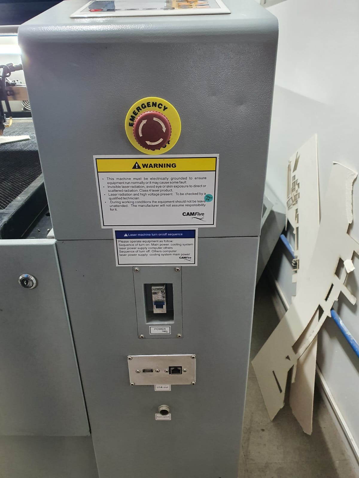
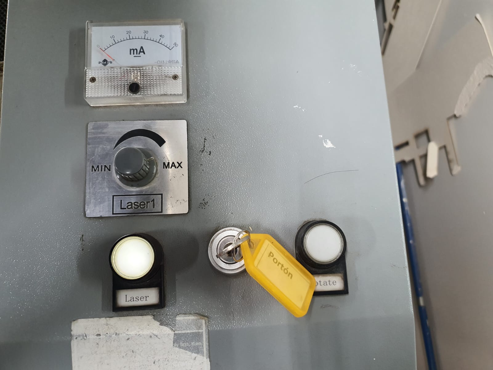
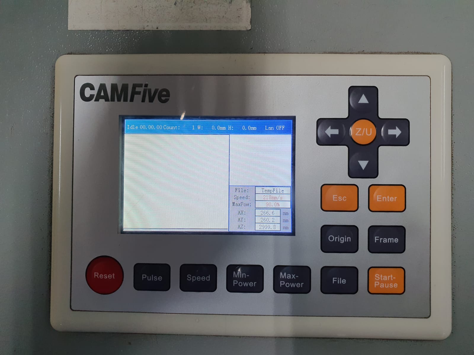
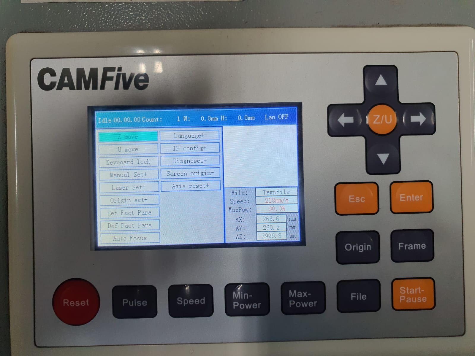
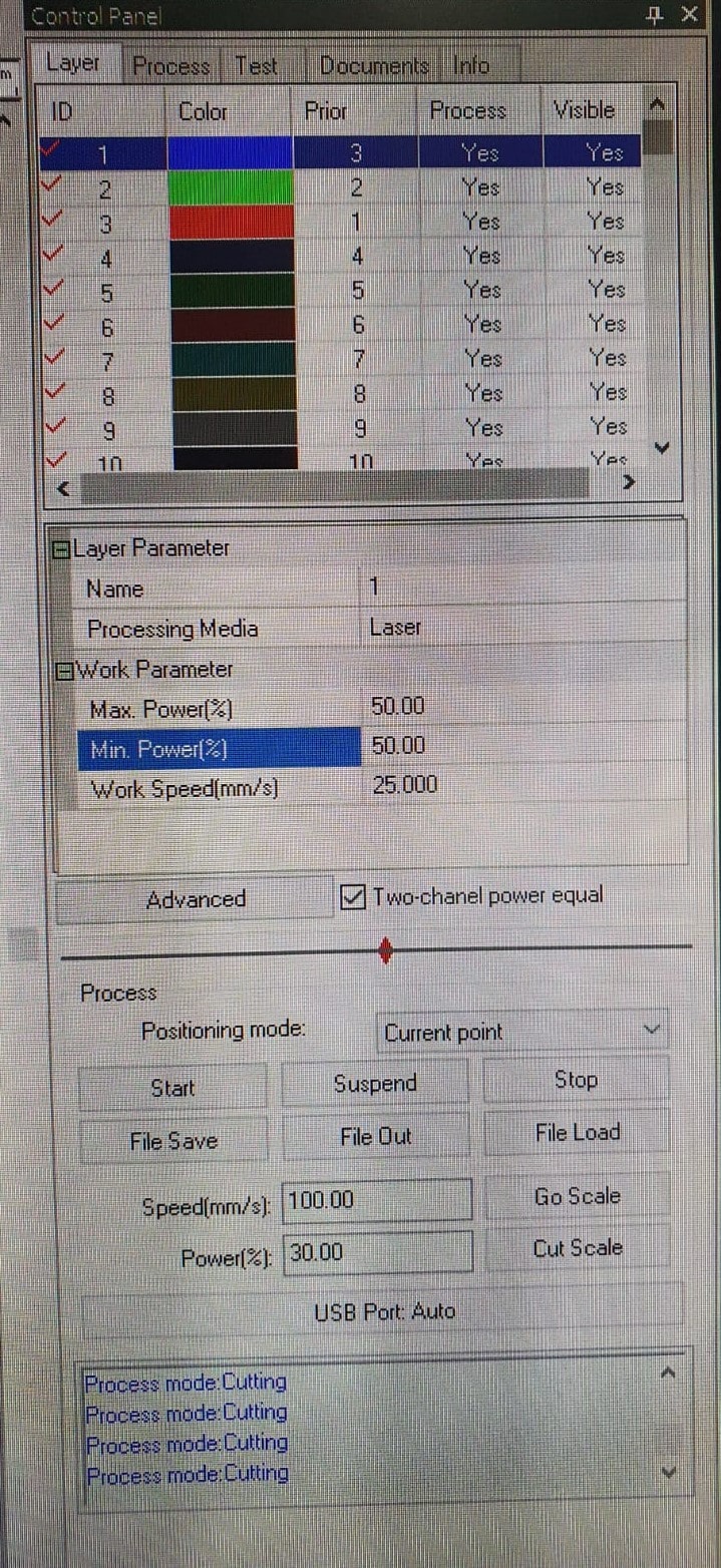
First of all, the most important thing when using the machine is its calibration. The LASER most important parts are:
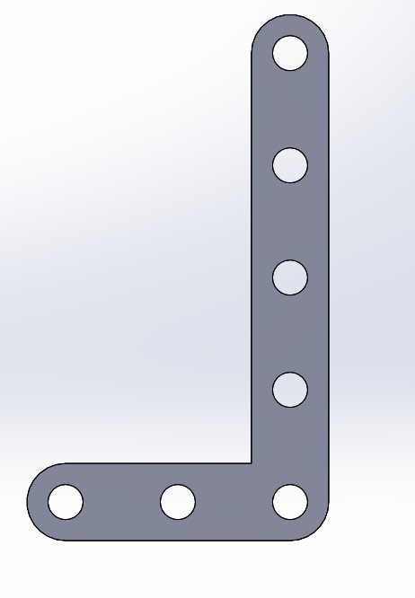
We can have different lengths of the bar by changing just 1 parameter (number of holes).
Just as the straight bar, we can change the lenght of the X and Y axis (2 parameters).
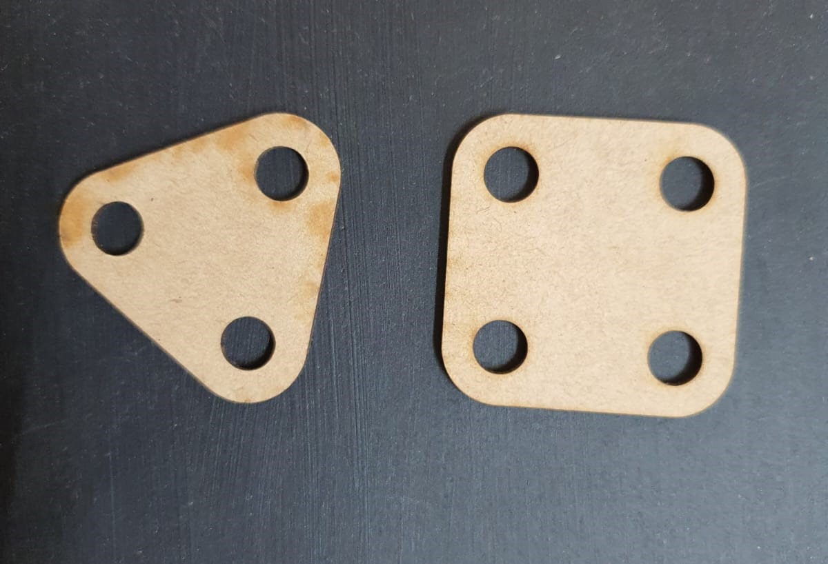
It can go as far as a circle, triangle, hexagon, etc. it only changes the number of sides.
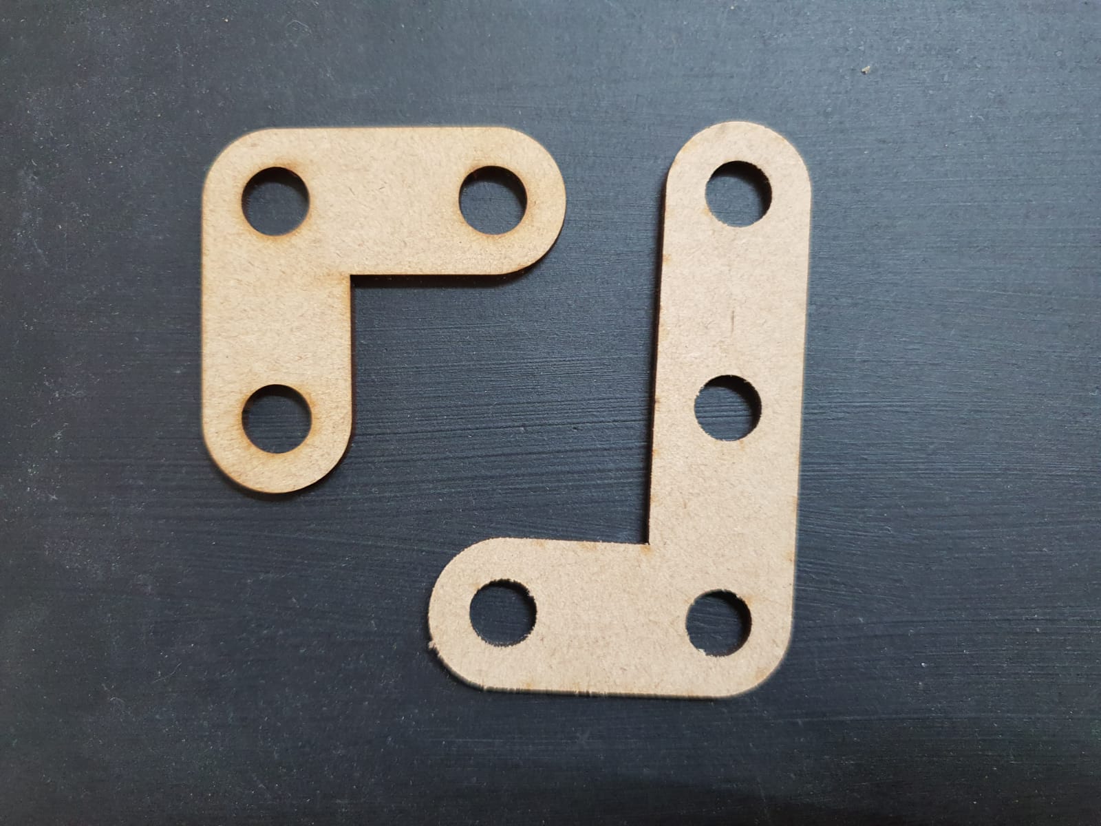
A bar with 2 perforations that can bend 45°, don't worry it all can be change in the angle paramter.
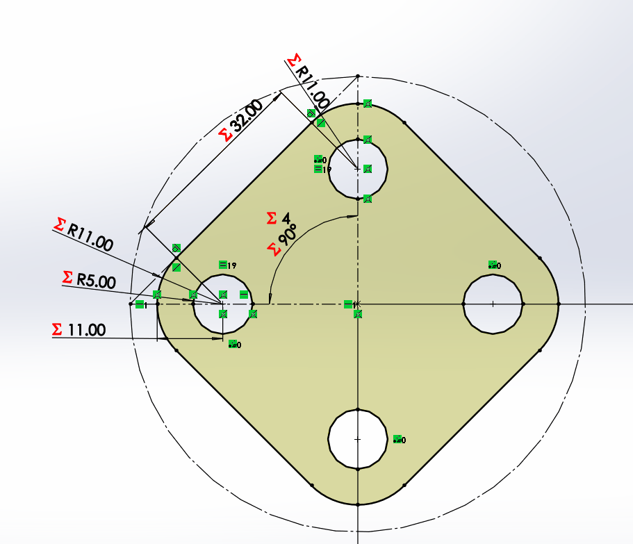
A three way bar with 45° every separation, 90° in total.
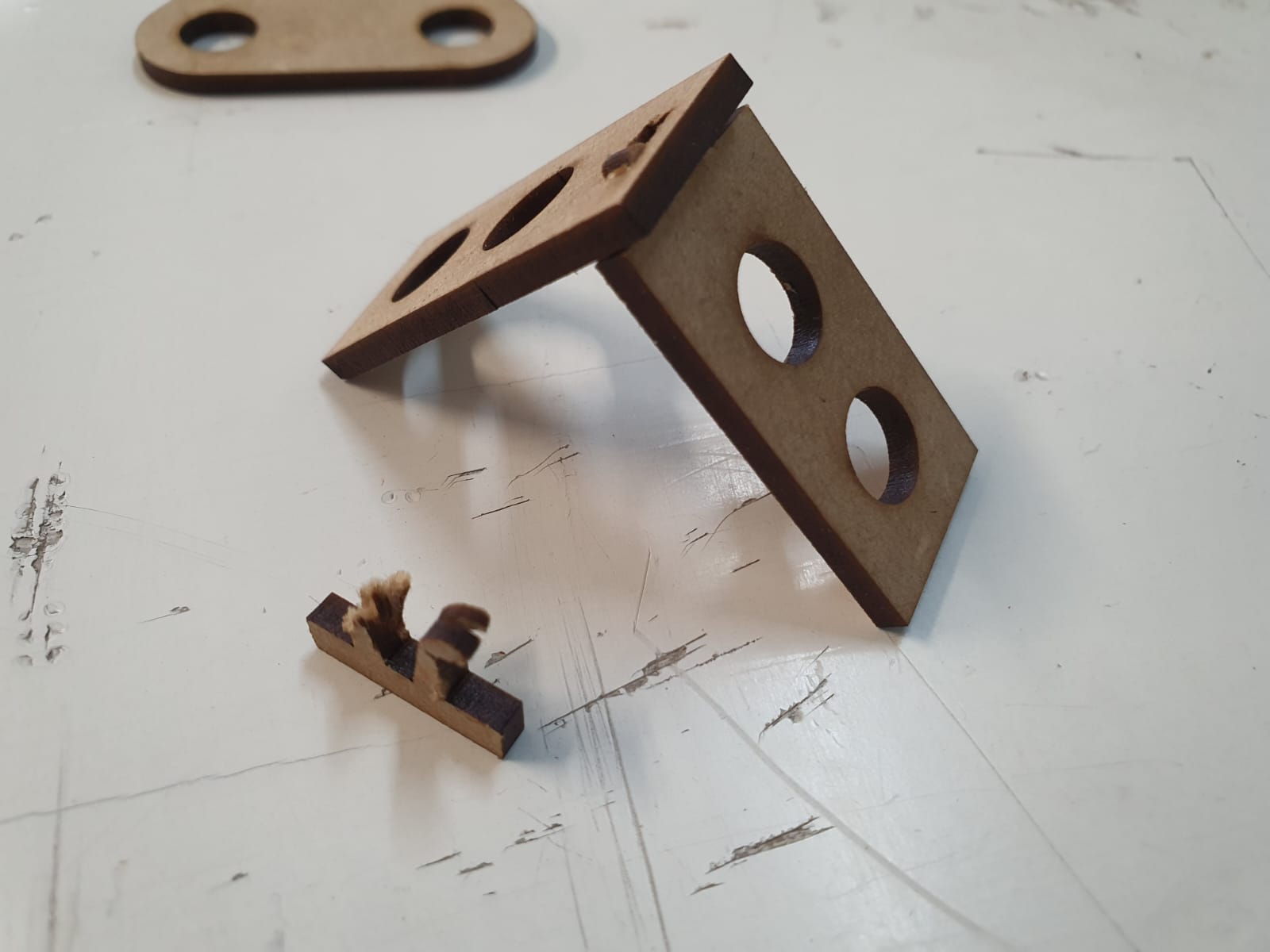
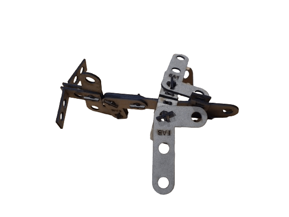
For changing the construction axis it is necessary an L, in this case with snap joints.
Counterpart of the snap L1, it can change its lenght.
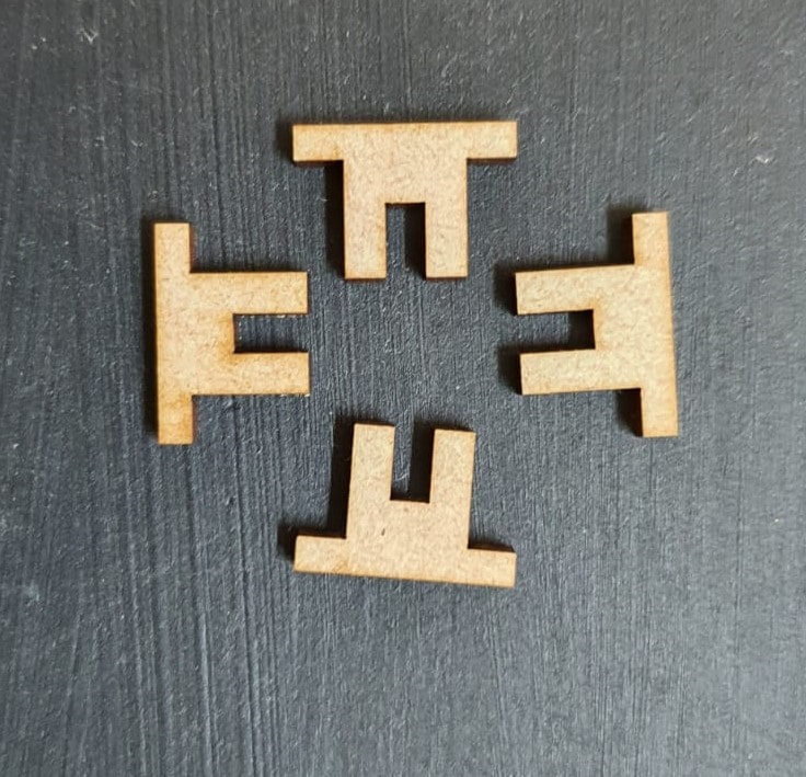
For last, joining all the parts together with a finger joint.
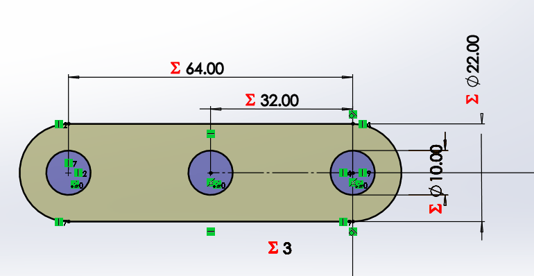
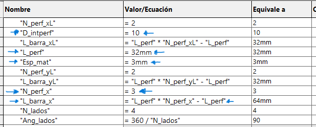
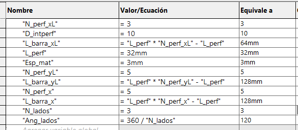
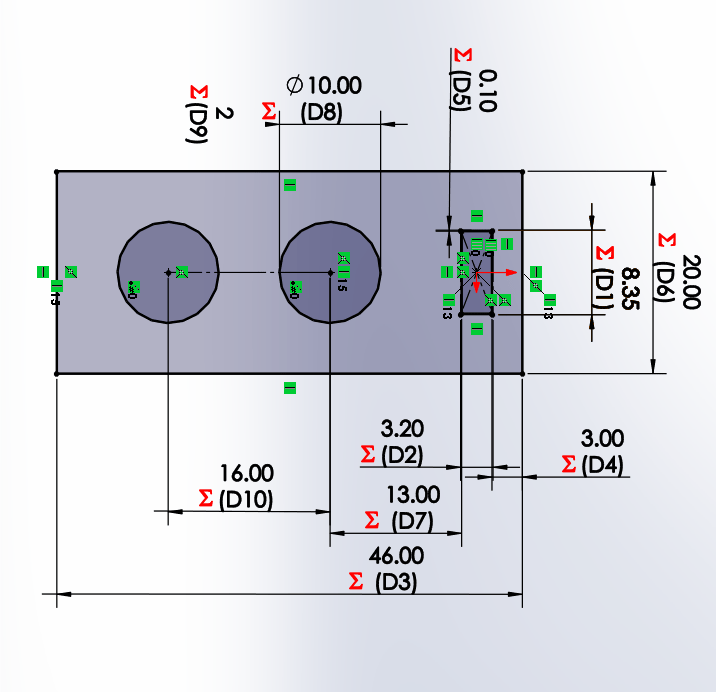
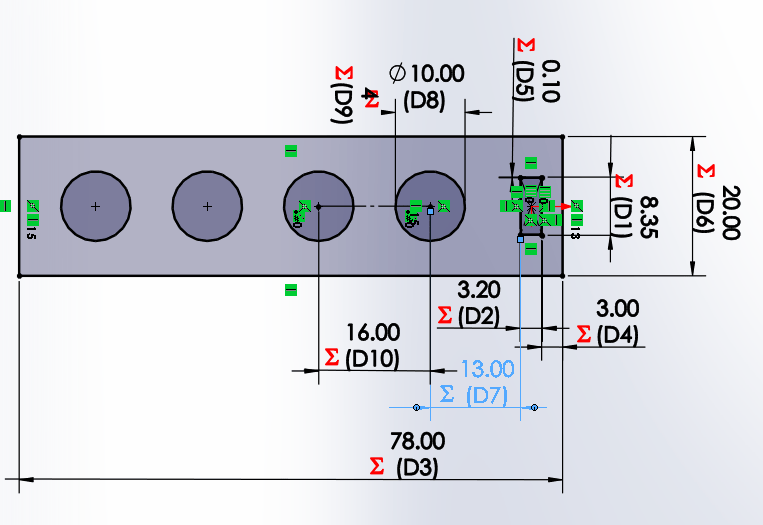
We start by drawing a bar with a circle, which has a horizontal linear matrix. In the figure we can see that the dimensions
have equations or dependent variables.
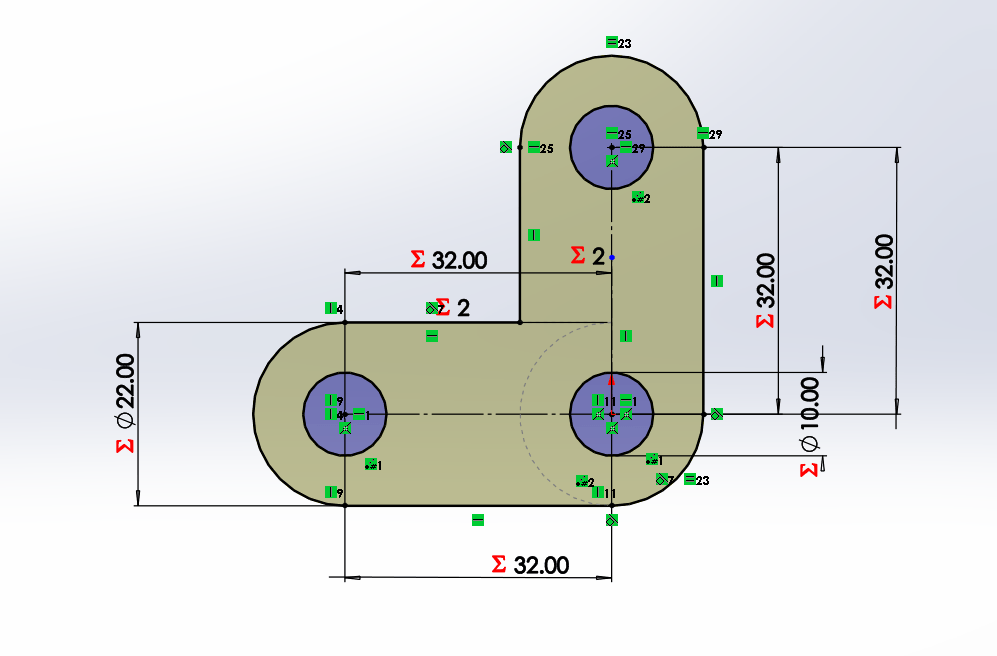
In the case of the L-bar it becomes relatively easy by having the straight bar, hedge because it is to perform the same procedure
for both X and Y axes. Each will have a length and number of holes that will change the distance of the links.
The creation of the square and triangle becomes more tedious because it depends on only one variable, the desired number of sides.
First we have to create a circle and place it as a construction object, then we place two construction lines, a horizontal line from the
center of the circle to the right point (180°) and another line from the center to any other point between 90° and 180°. Finally, we connect
these lines with a line that is bounded by the length of the hole. If you want to make internal perforations, place half circles on the
construction lines. In my case, to give it a more aesthetic touch, I added arcs at the intersections of the construction lines with the line.
With its equation to always maintain a distance of 6mm.

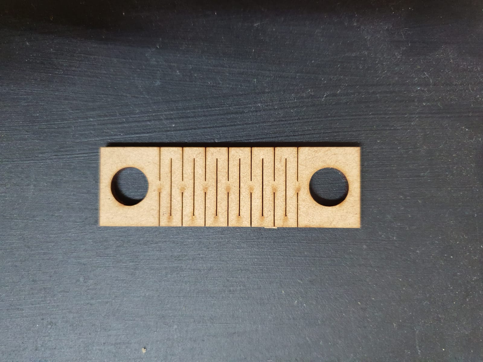
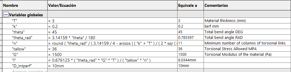
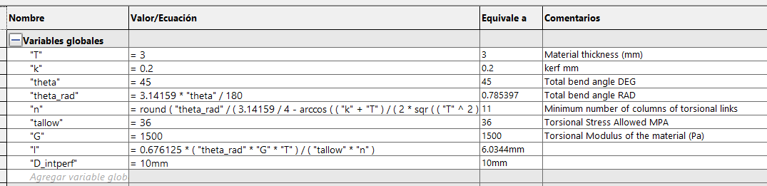
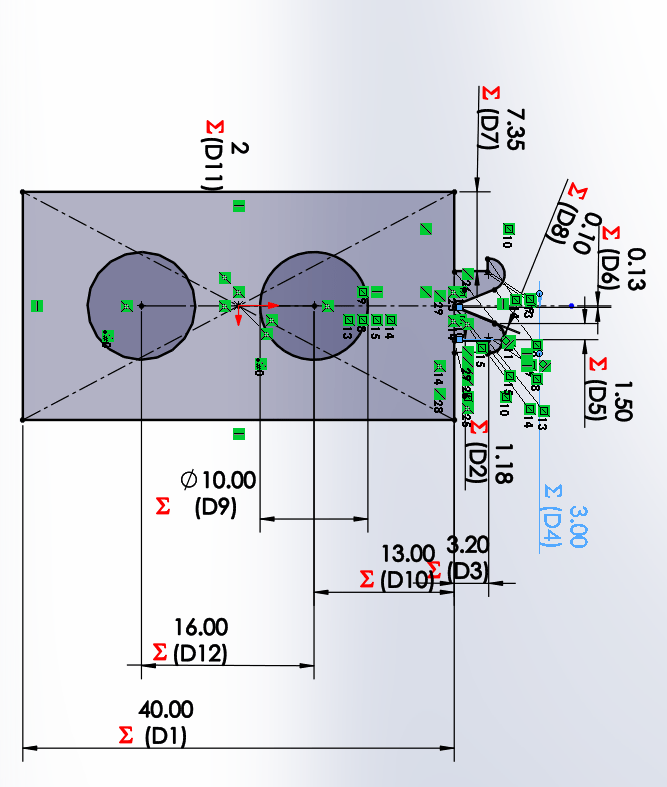
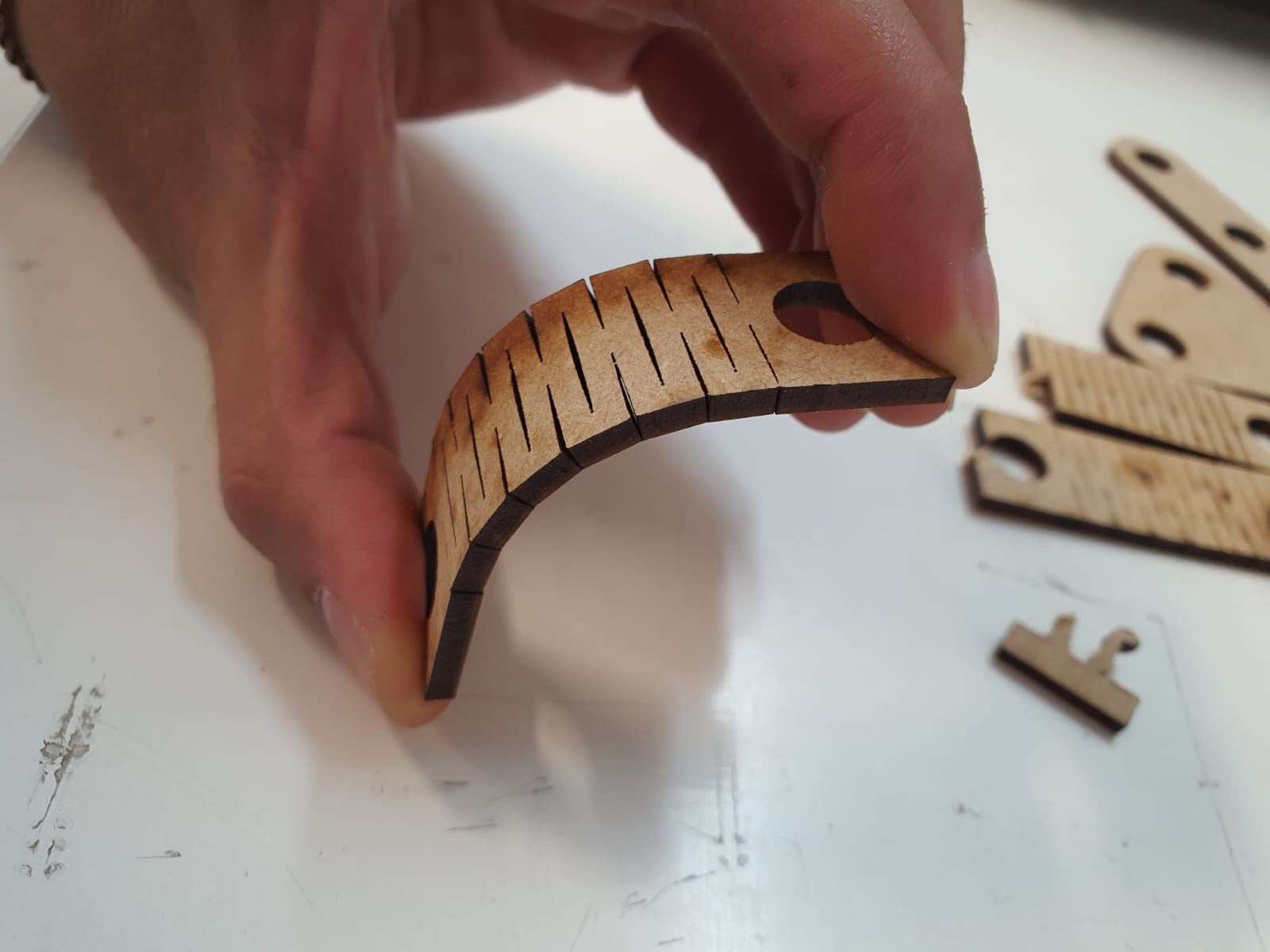
To make a flexible part we use the previous file with the flexibility formulas, by modifying the sketch adding the internal holes
and the final length we get something like this. Within the equations we can modify the material thickness, the kerf and the angle
we want to achieve with the part, in this case it is 45°. It is important not to extrude this part and keep it only as a sketch,
because if you give it a thickness, the partition lines for flexibility cause conflicts and it does not detect them.
Just remember to remove the unwanted sketch lines before cutting the part.
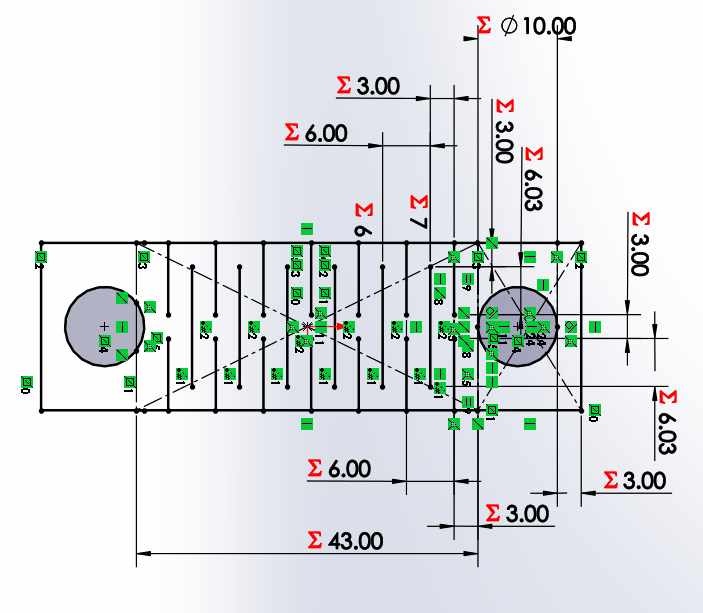
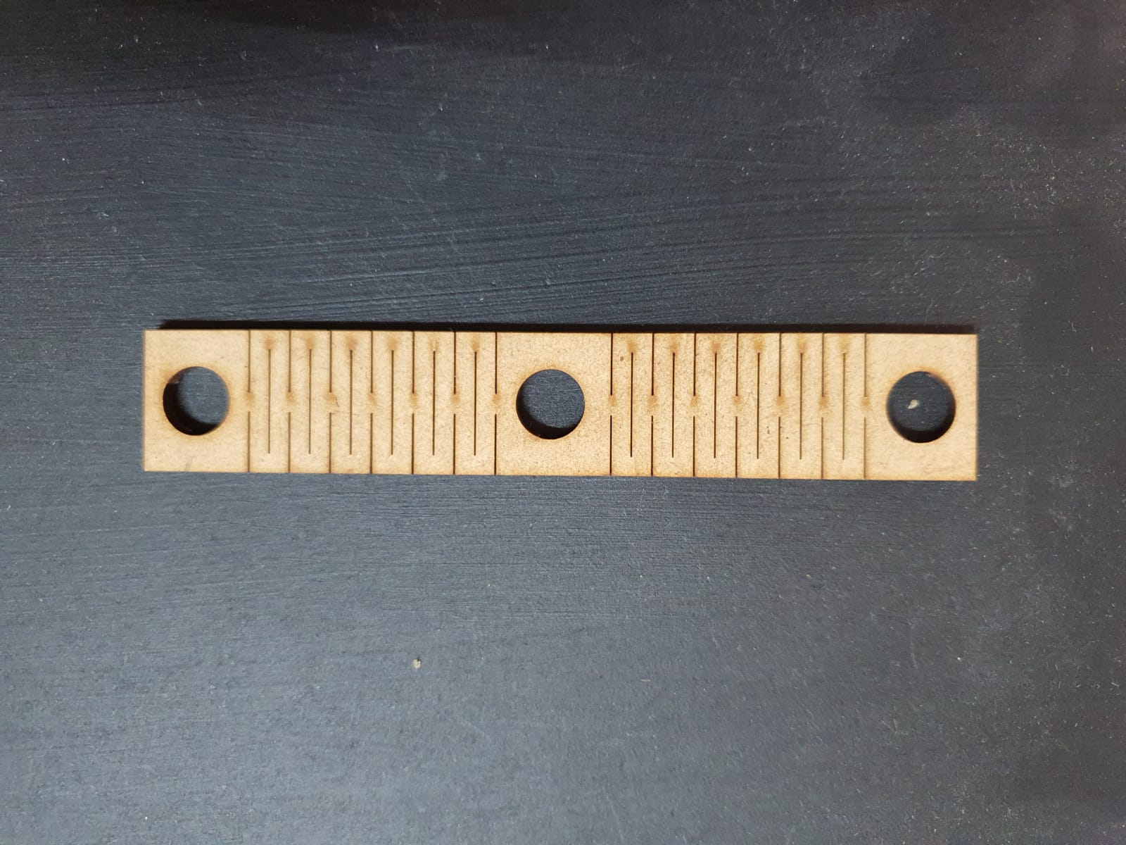
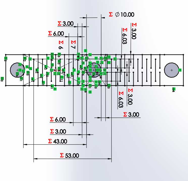
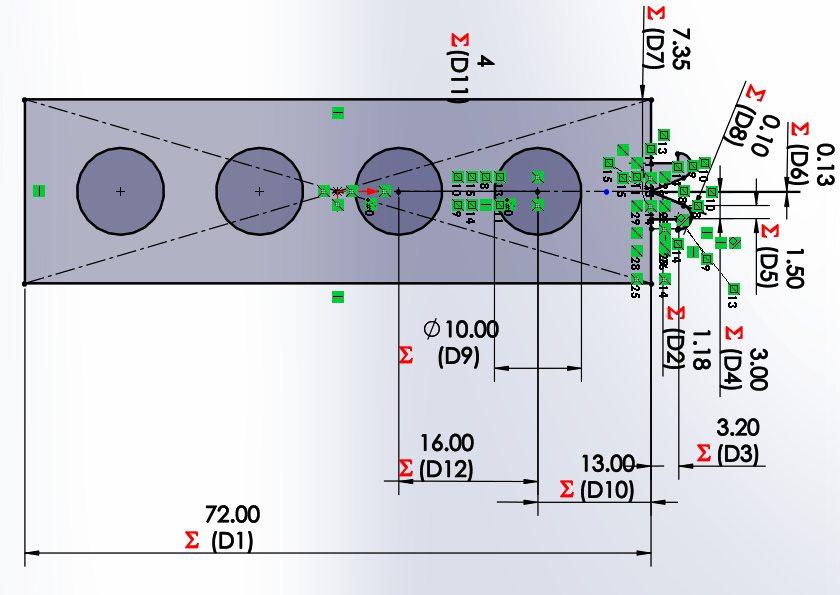
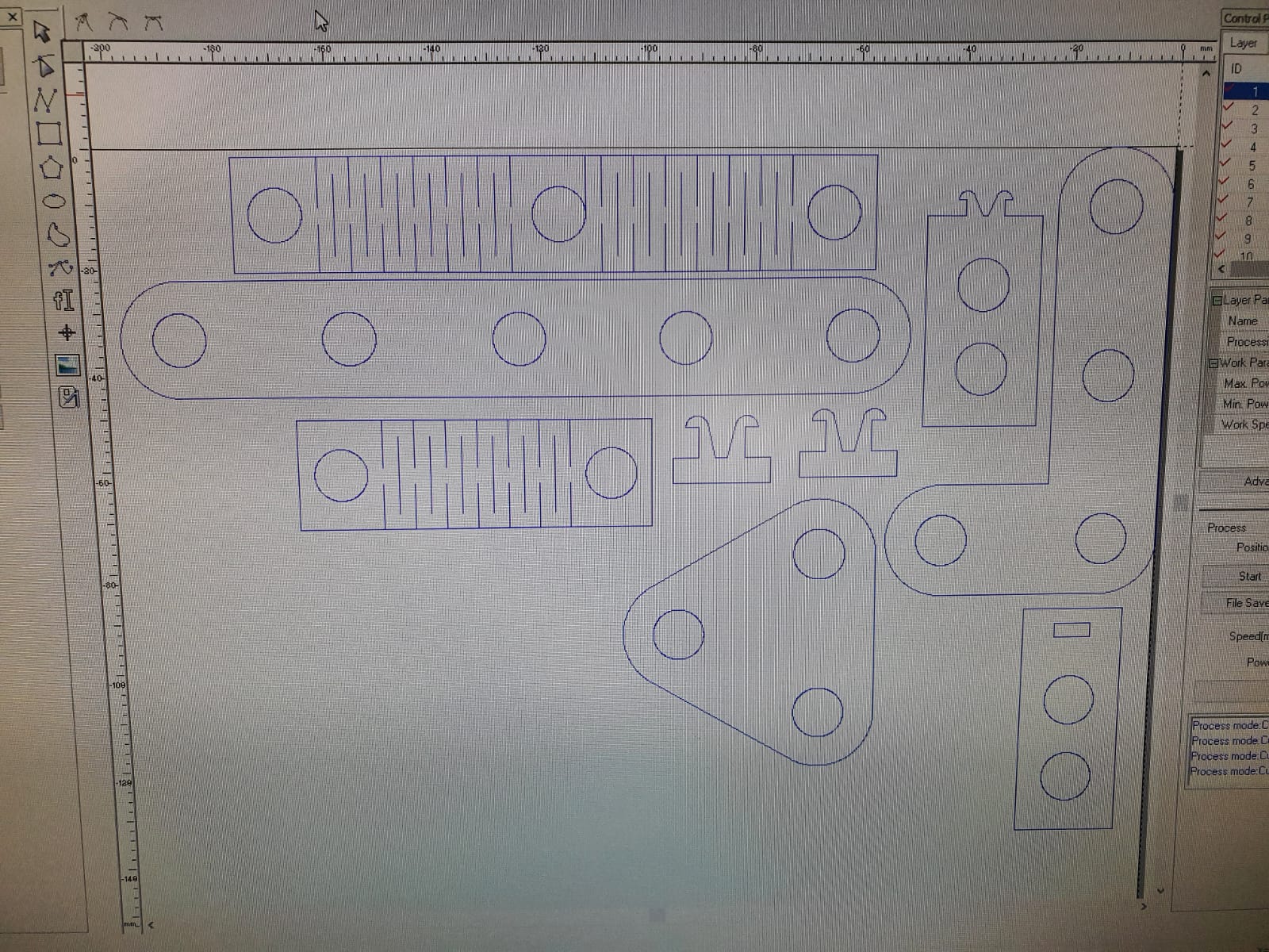
Using the previous design I added a matrix of the bending and drilling lines at the same distance as the drilling length of the previous figures.
I want to clarify that I tried to merge both designs into one or to be able to create larger dies, but I did not succeed.
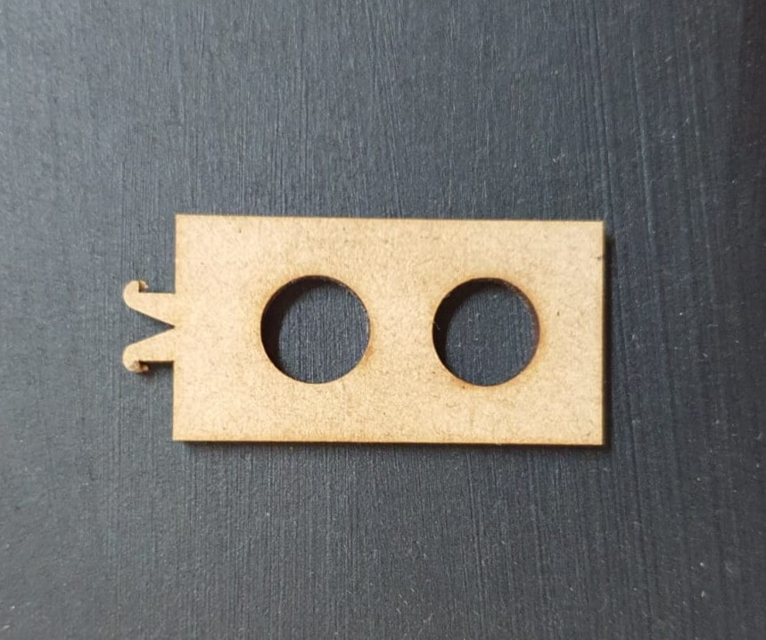
In order to be able to make changes of direction in the axes it is necessary to have a part that can make 90 degrees, to make this possible two SnapL
parts L1 and L2 will be used. Where L1 has a square hole and L2 has a snap type joint that will enter the hole.For the L1 joint we will
use the test design of the group, adding a combination of the bar to the rectangular part of the snap, where we can modify the number
of perforations that will be present, as well as the material used.

For Snap 2 the same thing happens in the same way, it will change its dimensions with respect to the material and the number of holes needed.

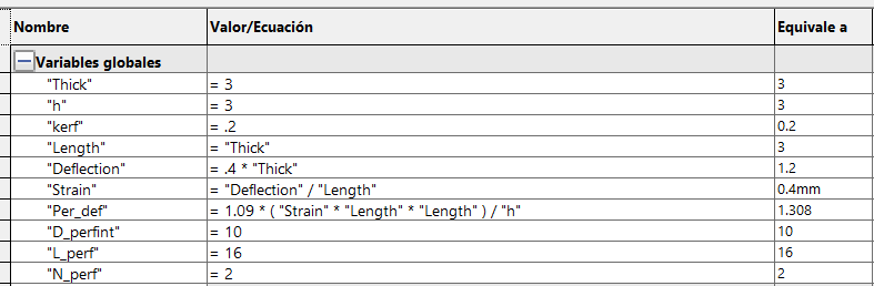
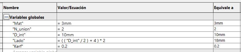
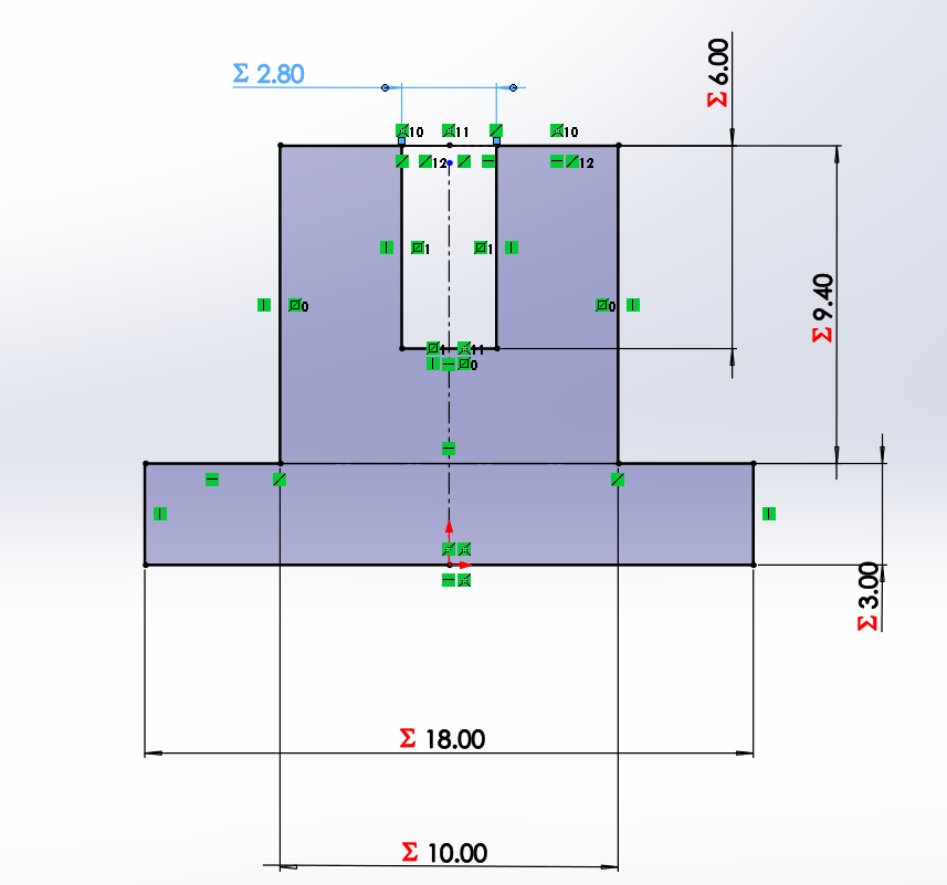
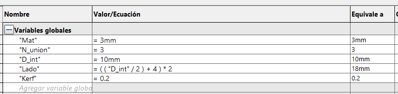
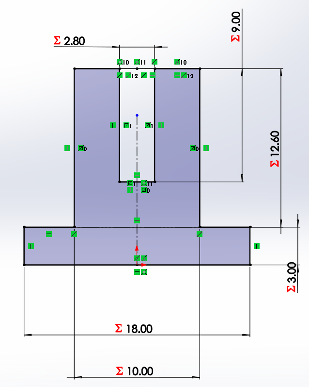
This part will be used to press 2, 3 or more parts together by changing 2 values the number of parts to be joined and the inner
diameter of the hole. In the sketch we define the height of the square and its perforation of the material thickness and the
kerf.
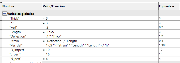
Parametric Design
Time is the most important resource in all areas of work, which is why the use of parametric part design is of the most importance.
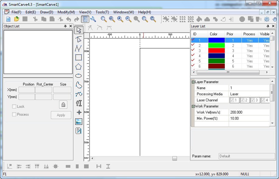
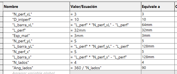
CAD software is built based on geometries, dimensions, and constraints that result in modifiable shapes and sizes. This type of design makes
it easy to modify and adapt models. In SolidWorks, you can create these constraints in the Equations part. When you open the window,
you can name a variable and a value (mm, m, angle, number, etc.) that will be stored in the system. When dimensioning a contour,
you can place this variable so that it always depends on it, it is placed with a =" Variable" or in the same way it can be used with
a mathematical equation, for example: =" Variable" * 0.5 + "Variable2". By having n variables depending on one, you can change the length,
perforation, position, etc. by changing a single value.
Test

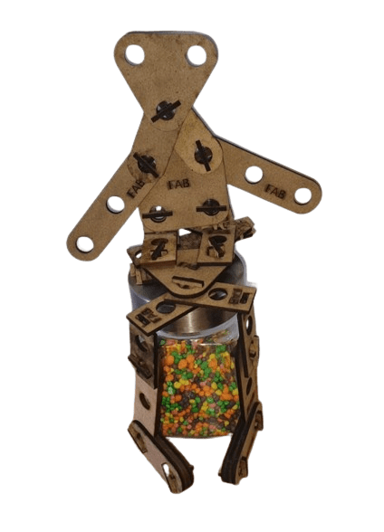
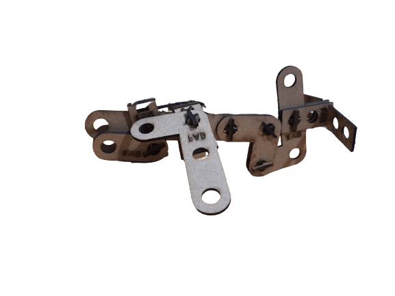
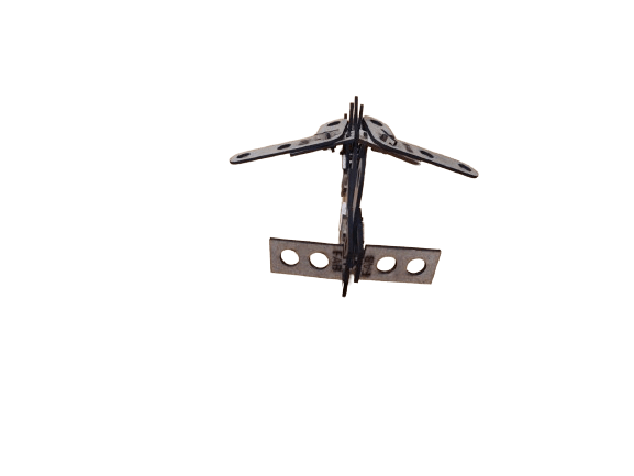
After getting all the pieces cutted it its time to asssemble some figures, is up to your imagination.

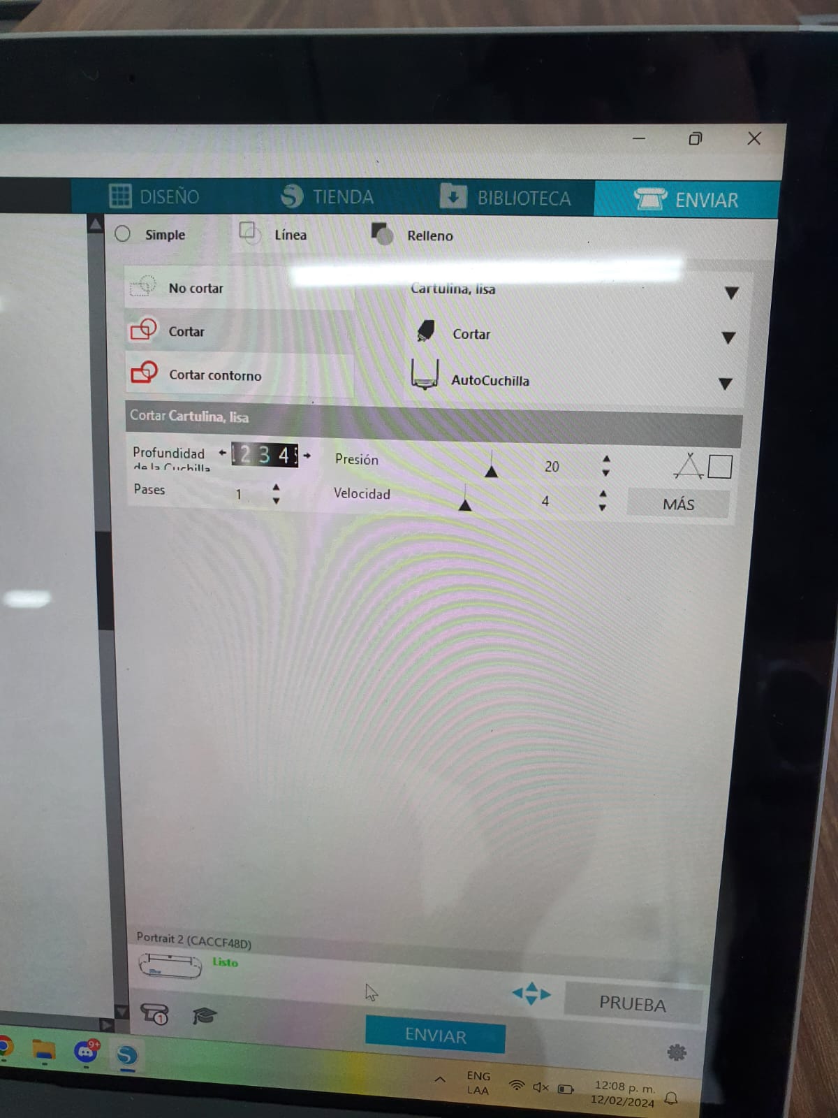
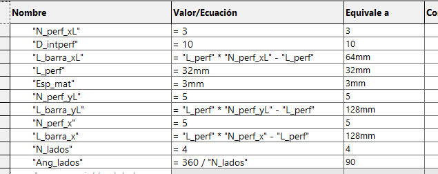
NOTE: I always created the equations and global variables one by one when I created a new part, but then I was told that you can link variables. If you want to use this function in your designs so that you don't have to waste time copying variables, at the bottom of the equations there is a linking part, clicking on it will ask you to select a file, it must be a .txt file, if you link the file with several parts you will always have the same dimensions and parameters (if you change one you change them all).
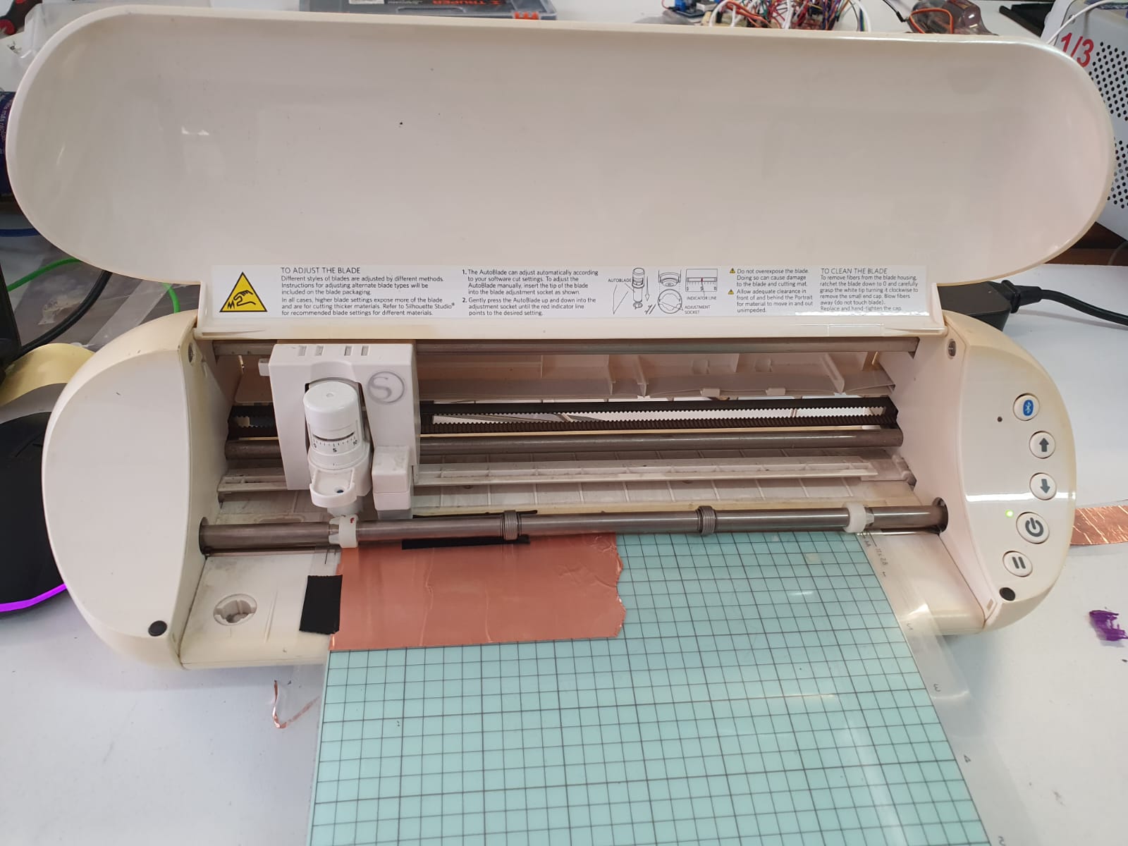
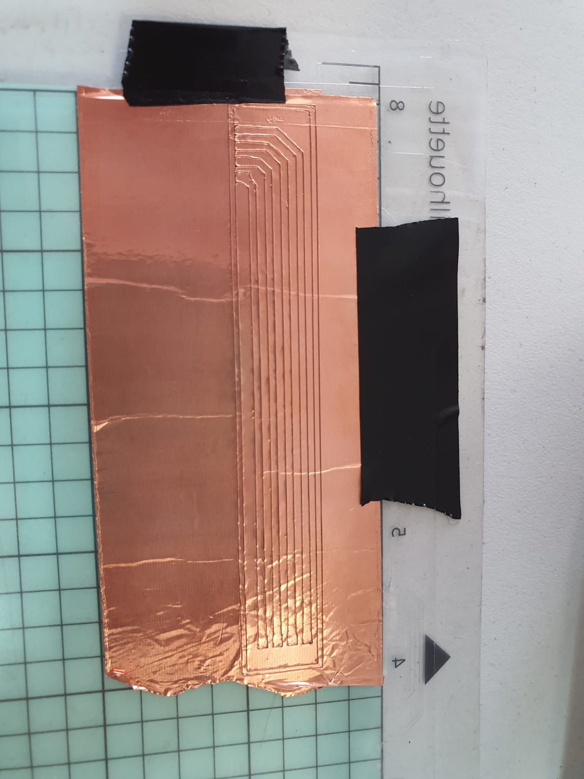
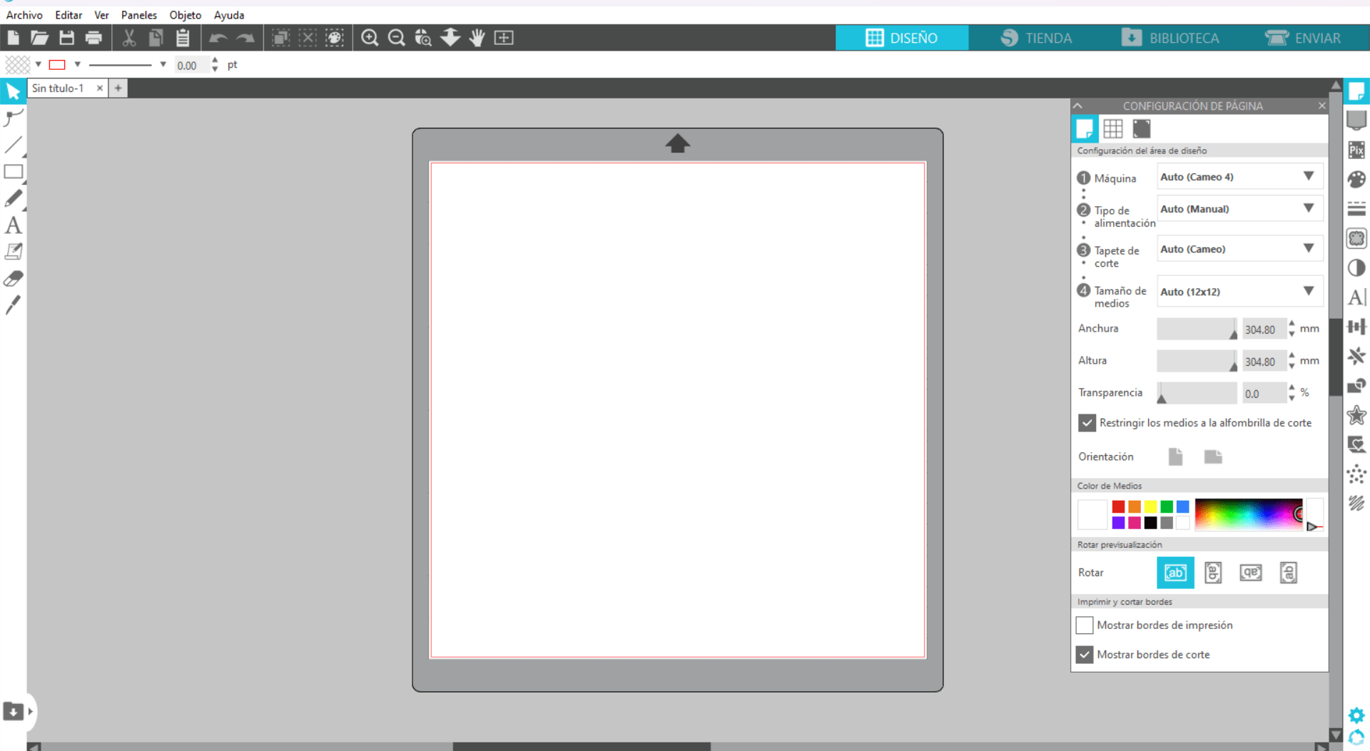
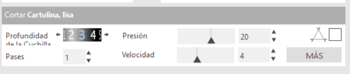
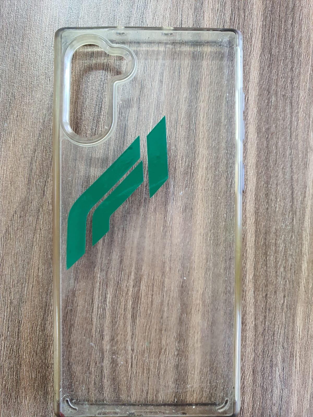
The Vinyl cutter use a small knife to cut the outline of a picture or DXF (vector) into a sheet of different material.