WEEK10 - Mechanical Design and Machine Design
This page covers the two weeks that were spend on machine design and machine production.
The aim of these weeks was to design and produce a whole functioning machine within the scope of these two weeks.
For the sake of philosophical exploration we chose to do a POINTLESS MACHINE. ‘pointless’ here is a an argumentative term to explore the meaning of functioning fabrication, as well as what we outsource to machines. This machine is a holiday-machine. The existence of this machine is both an exploration of what we choose to outsource to machines, or do we get to re-engage with lost aspects of life through the machines..... or is it entirely pointless to consider this from a human centric perspective.
WEEK TEN & ELEVEN ASSIGNMENT
- characterize the design rules for your in-house PCB production process extra credit: send a PCB out to a board house
HERO VIDEO
THE MANIFESTO
The Fabmachines work too hard. They deserve a break and they deserve to go on holiday. To keep the mental health of the machines in tact as well as outsource our own mental health needs, we confront ourselves with the needs of machine care and machinic health. A plotter tool seeking zen and too leave its exploitative lab-life behind, finds the beach, as it takes a break from human-driven fabrication and instead engages with worldly and other worldly contemplation. The machine seeks to engage with nature to consider events happening right infront of it as well as far away.
We take time to observe and discuss the machines thoughts. We value it’s opinion and make sure the machine knows it’s more than just a tool.
We are happy for the machine.
And through watching the machine relaxation which it does not need, we feel better about the exploitative life-style we leave towards our own limited meat-shell resources.
Through the machine as the proxy, we too can learn to enjoy nature again
Time Schedule:
Spiral1: make thing do thing: cnc sand drawint machine using normal gcode. ( possible battery power)
Spiral 2: add wheels/ design weels ( keep this in mind duriny design of lenght of drawing tools)
Spiral 3: run machine using python instead of model.
Plan:
Day 1( 31/03) Finish manual movement of cnc movement- fix stepper motor issues. Finish actuator plate design- start printing ( servo motor movement decisions)
Day2 (01/04) Make maschine run using normal gcode model ( spiral 1 finish)
Design and cut wheels using lasercutter ( spiral 2 fullfilled ) If time start python code.
Day 3 ( 08/04) coding
Day 4 (09/04) filming Shoot b-roll during day 1+2
Dismantled 3D Printer Base
For the foundation of the machine we dismantled an existing 3D printer that was used for a previous Kamakura Fab Academy machine group project - Juicy Messenger.
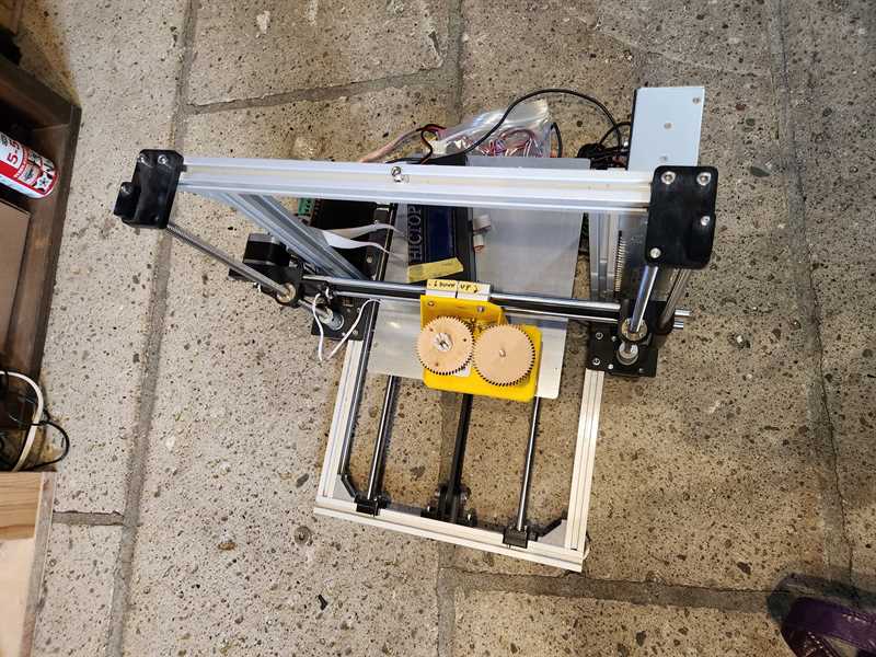
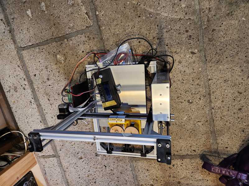
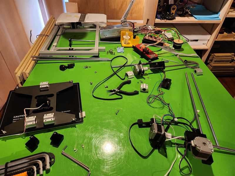
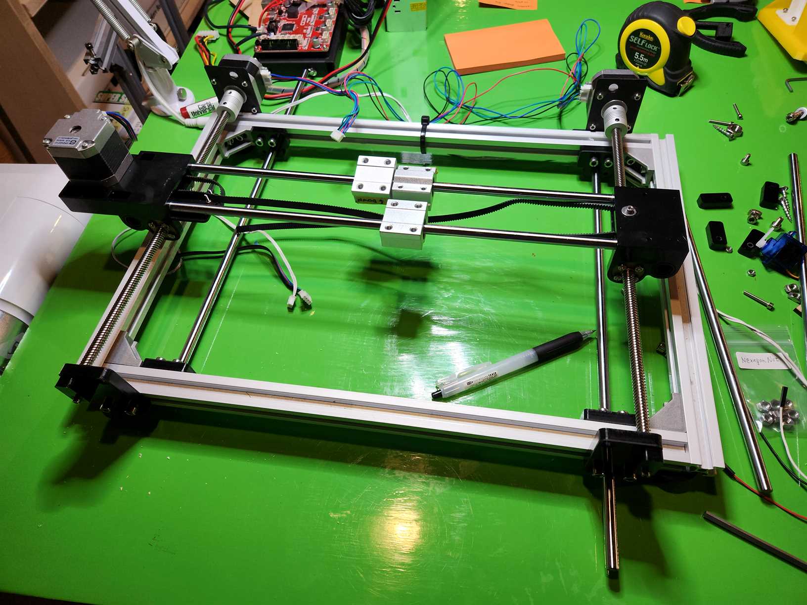
We started by exploring how the original machine worked by moving the parts manually while it was off. The machine was originally a 3D printer where the bed moved on the y direction on lead screws and another set of lead screws moved the head in the z direction and a belt moved the head in the x direction.
We decided that to work for our project we needed to change it so that what was the z axis became the y axis and x remain the same.
After pulling everything apart we were able to reassemble the original machine to our new configuration and move it by hand in the x and y direction. The x direction uses a belt around a cogged pulley attached to a stepper motor and the y uses two lead screws each attached to a stepper motor.
We had some alignment/wonkyness issues with the lead screws, but we were able to resolve this by making sure everything was tight and straight (definitely a two person job).
DISTRIBUTION OF WORK
So when working on this project we decided to work jointly in the sense that all decisions were made together, however we also both had key skills that we wanted to highlight and also some dynamics naturaly developed.
We were also told that both of us needed to design something so we had to also distribute labor this way:
Overall, Kat was responsible for the video production and the actuator design.
Claire on the otherhand, did most of the heavy lifting for this project, she came up with the process and code for how to make the idea work, and with her engineering background was primarily responsible for the machine design and most all of the coding. She participated in the design of the gear. but also made the wheels and the battery mechanism.
Link to Individual Pages
Kat
Claire
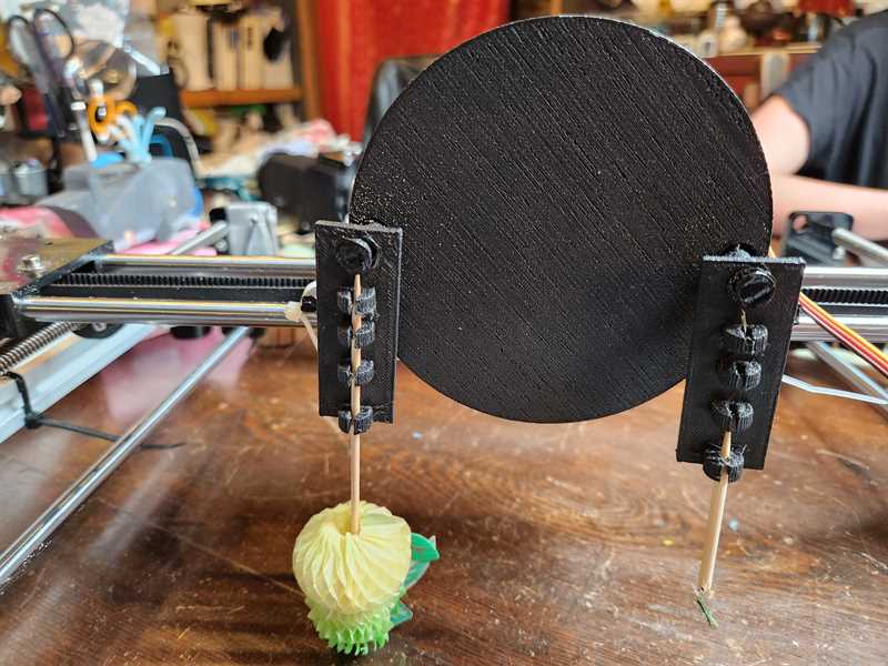
ROTATION ACTUATOR
For the actuator, beyond the functioning x;y plotter we also needed to design a plate which would


On top of the plate we also designed a rotating plate with the two holders for the alternating drawing utensils.


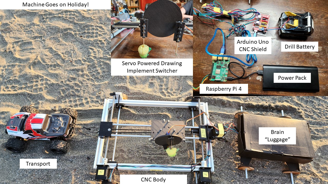
Controlling the Stepper Motors - Arduino Uno
The dismantled and reconfigured 3d Printer originally used two stepper motors for the z axis, now the y axis and one for the x axis, still x axis.
To control these stepper motors we decided to use an Arduino Uno with a CNC Shield.
Stepper Motors used were Quimat Motor 17HD48002H-22B. These were changed from the original steppers used for the 3D printer.
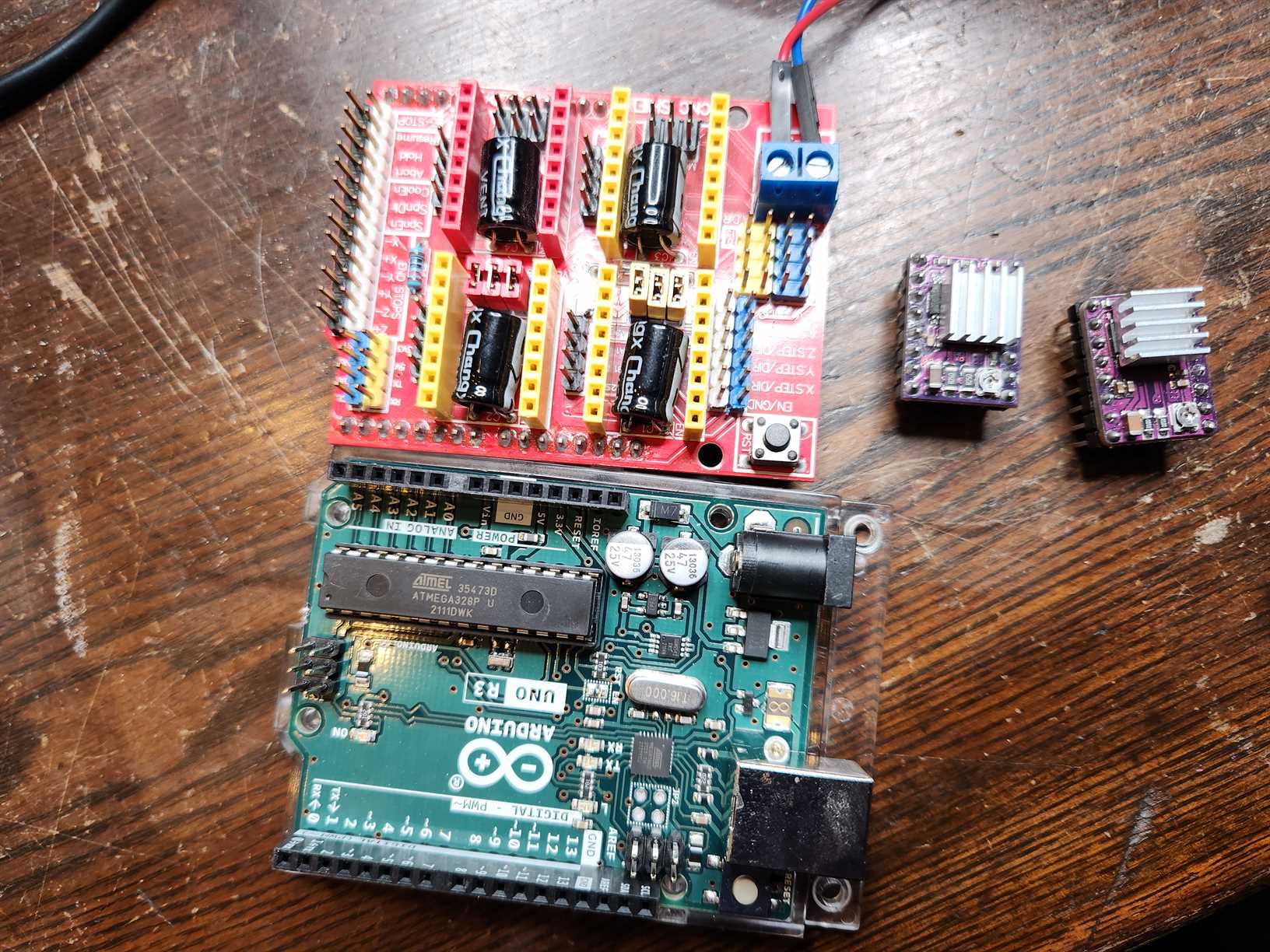
CNC Shield Setup
Components:
- CNC Shield (HiLetGo V3)
- 2x Stepper Drivers
- 6x Micro Steppers
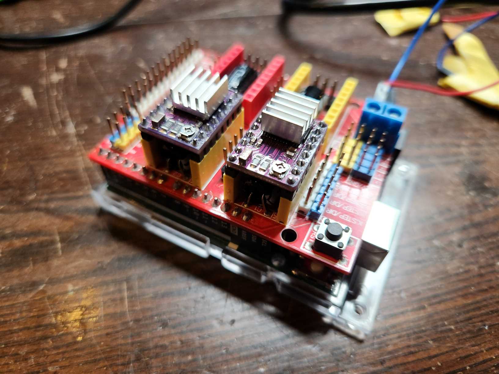
The two y stepper motors were wired together and then connected to y on the CNC Shield.
The x stepper motor was wired to the x on the CNC Shield.
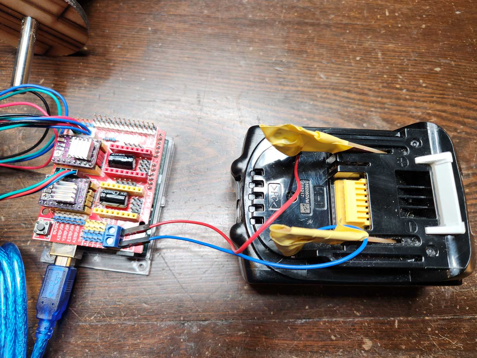
The CNC Shield was then connected to separate power form the Arduino, to allow for the right amount of power to be fed to the steppers and to protect the Arduino from power fluctuations created by the stepper motors. Through testing of this particular setup we found that we needed at least 15V with at least 2Ah to power the setup and move all the motors.
Note: For the CNC Shield max power input is 36V and 3Ah.
Arduino Uno Setup
To control the steppers through the CNC Shield we used Grbl. This was loaded onto the Arduino by doing the following:
- Download grbl from Github https://github.com/gnea/grbl
- Download a zip file of the code grbl-master.zip
- Load the zip file as a library in the Arduino IDE
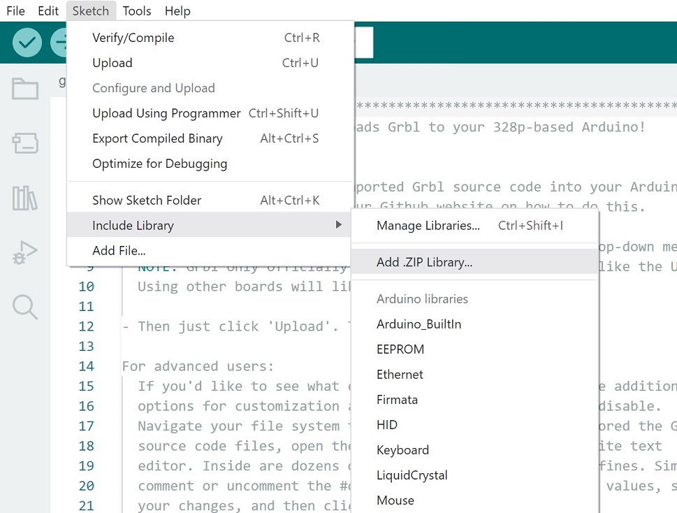
- Open the grblUpload Example Code and upload it onto the Arduino
grblUpload Code
/***********************************************************************
This sketch compiles and uploads Grbl to your 328p-based Arduino!

To use:
- First make sure you have imported Grbl source code into your Arduino
  IDE. There are details on our Github website on how to do this.

- Select your Arduino Board and Serial Port in the Tools drop-down menu.
  NOTE: Grbl only officially supports 328p-based Arduinos, like the Uno.
  Using other boards will likely not work!

- Then just click 'Upload'. That's it!

For advanced users:
  If you'd like to see what else Grbl can do, there are some additional
  options for customization and features you can enable or disable.
  Navigate your file system to where the Arduino IDE has stored the Grbl
  source code files, open the 'config.h' file in your favorite text
  editor. Inside are dozens of feature descriptions and #defines. Simply
  comment or uncomment the #defines or alter their assigned values, save
  your changes, and then click 'Upload' here.

Copyright (c) 2015 Sungeun K. Jeon
Released under the MIT-license. See license.txt for details.
***********************************************************************/

#include <grbl.h>

// Do not alter this file!
We were able to test functionality using universal G-code Sender.
Battery Power for Stepper Motors
One key requirement for the machine was to be able to run it at the beach away from mains power. As such we needed a battery.
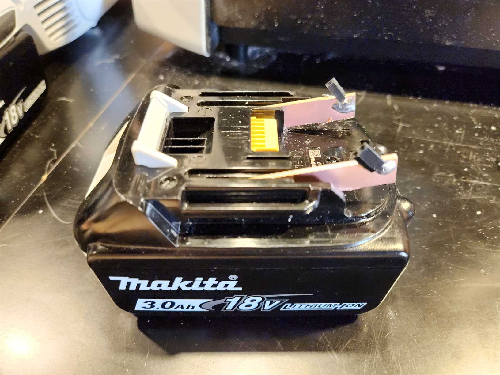
We could have gone an bought a battery, however we decided that we could use what we had available in the Lab, an 18V 3Ah battery from a drill.
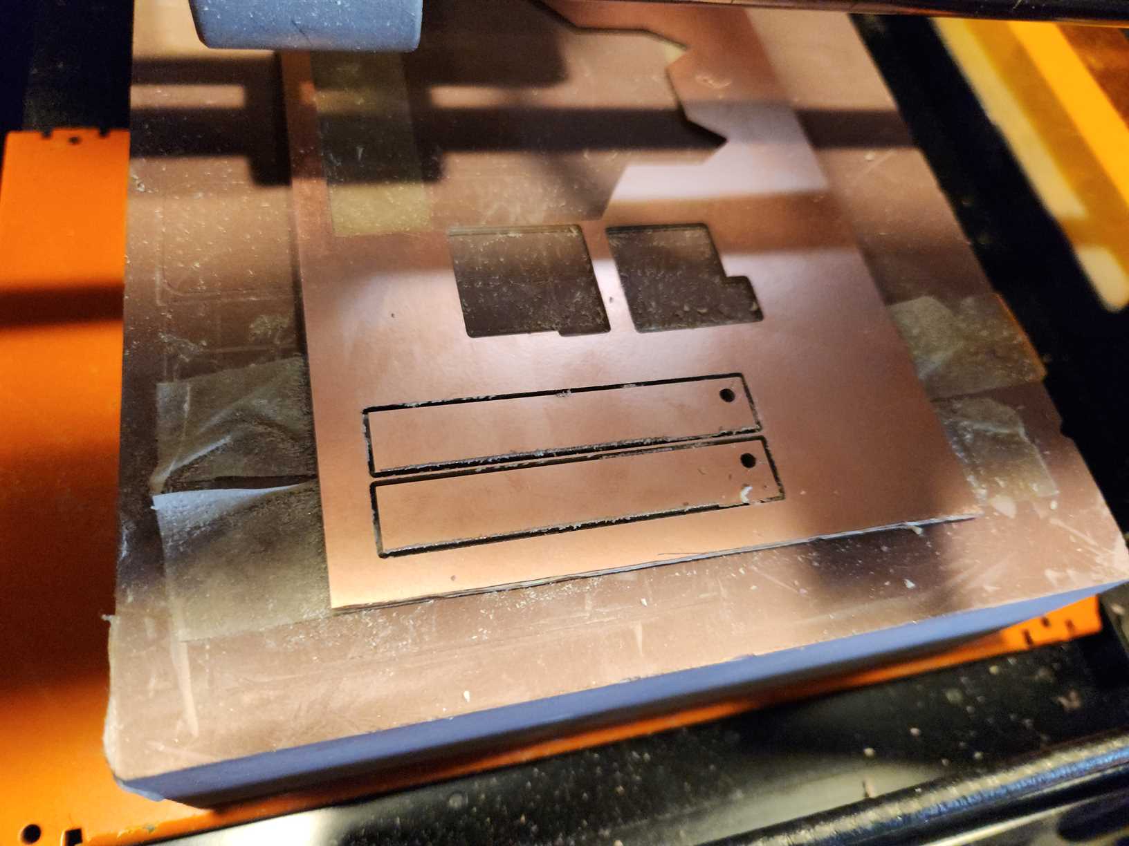
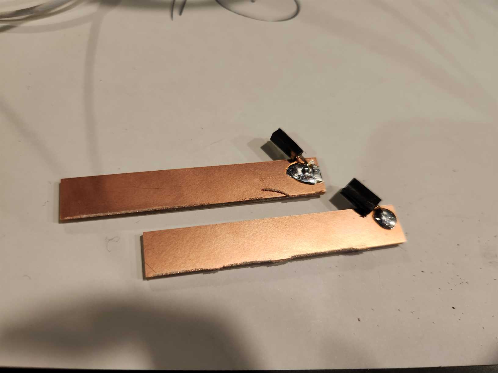
This battery had clearly labelled positive and negative terminals. Copper PCB material from the SRM-20, was a perfect fit in the terminals.
We used the SRM-20 to cut out two rectangular pieces of board, we then soldered a female terminal on each board to plug positive and negative wires from the CNC Shield into.
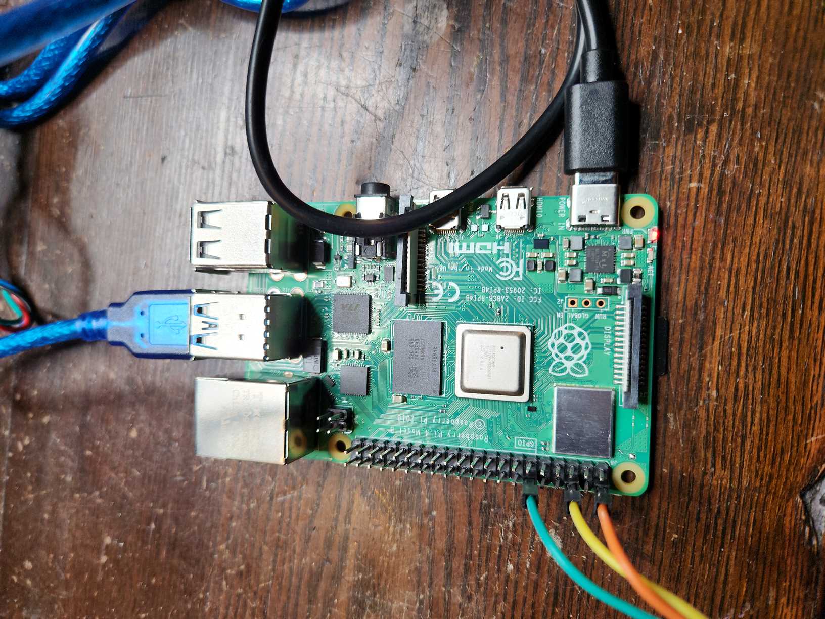
Controlling the Arduino and Servo - Raspberry Pi 4
To allow for the machine to be remotely controlled we decided to use a Raspberry Pi 4.
First test was to install and use Universal G-code Sender on the Pi to control the stepper motors. This worked.
Next step was to be able to send a looped code that produces a random pattern.
CNC Code
We can use Python to send G-code to the Arduino from the Pi over Serial. You just need to make sure that you have the correct name for the port the Arduino is on when connected via USB to the Pi.
We utilised ChatGPT to help us with writing the code, this was both to save time, but also to test ChatGPT’s capabilities in coding.
First we asked it to create code for drawing a circle
# Made by ChatGPT April 2023
import serial
import time
import math

ser = serial.Serial('/dev/ttyACM0', 115200, timeout=1) # Replace ttyACM0 with the appropriate port for your Arduino Uno

def send_gcode(gcode):
    ser.write(str.encode(gcode + '\n'))
    grbl_out = ser.readline().decode('utf-8').strip()
    print('sent: ' + gcode)
    print('received: ' + grbl_out)

send_gcode('$X') # send the kill alarm command to reset the Arduino Uno

send_gcode('G21') # set units to millimeters

send_gcode('G90') # set absolute positioning mode

send_gcode('G0 X0 Y0 Z5 F1000') # move to the starting position

radius = 15 # 30mm diameter circle has a 15mm radius
angle_step = 10 # step size in degrees

send_gcode('G1 X{} Y{} F1000'.format(radius, 0)) # move to starting point on circle

for angle in range(0, 360, angle_step):
    x = radius * math.cos(math.radians(angle))
    y = radius * math.sin(math.radians(angle))
    send_gcode('G1 X{} Y{} F1000'.format(x, y)) # move to next point on circle

send_gcode('G1 X{} Y{} F1000'.format(radius, 0)) # return to starting point on circle

ser.close() # close the serial connection
When then asked for a wave like pattern. ChatGPT came up with using a sine wave.
# Made by ChatGPT April 2023
import serial
import time
import math

ser = serial.Serial('/dev/ttyACM0', 115200, timeout=1) # Replace ttyACM0 with the appropriate port for your Arduino Uno

def send_gcode(gcode):
    ser.write(str.encode(gcode + '\n'))
    grbl_out = ser.readline().decode('utf-8').strip()
    print('sent: ' + gcode)
    print('received: ' + grbl_out)

send_gcode('$X') # send the kill alarm command to reset the Arduino Uno

send_gcode('G21') # set units to millimeters

send_gcode('G90') # set absolute positioning mode

width = 100 # set the width of the rectangular area to draw in
height = 100 # set the height of the rectangular area to draw in

# set the starting position of the machine
start_x = width / 2
start_y = height / 2

# set the amplitude and period of the sine wave
amplitude = 10
period = 20

# set the step size for the curve
step_size = 0.5

# set the movement speed of the machine
speed = 1000

# set the color of the line
#line_color = (255, 255, 255)
x = 1
# loop to draw a continuous line
while True:
    # move the machine in a sine wave
    for b in range(0, width):
        #y = round(start_y + amplitude * math.sin(math.pi * x / period))
        x = x
       # limit y to a maximum of 100 using an if statement
        if y > height:
            y = height

        if x > width
            end for

        send_gcode('G1 X{} Y{} F{}'.format(x, y, speed))
        x = x + 0.5


    # wait for the machine to finish moving
    time.sleep(0.1)
The sine wave code was then modified to change the x to two loops so that the machine would move the x axis back and forth.
# Made by ChatGPT, modified by Claire Chaikin-Bryan April 2023
import serial
import time
import math

ser = serial.Serial('/dev/ttyACM0', 115200, timeout=1) # Replace ttyACM0 with the appropriate port for your Arduino Uno

def send_gcode(gcode):
    ser.write(str.encode(gcode + '\n'))
    grbl_out = ser.readline().decode('utf-8').strip()
    print('sent: ' + gcode)
    print('received: ' + grbl_out)

send_gcode('$X') # send the kill alarm command to reset the Arduino Uno

send_gcode('G21') # set units to millimeters

# send_gcode('G90') # set absolute positioning mode

width = 100 # set the width of the rectangular area to draw in
height = 100 # set the height of the rectangular area to draw in

# set the starting position of the machine
start_x = width / 2
start_y = height / 2

# set the amplitude and period of the sine wave
amplitude = 10
period = 20

# set the step size for the curve
step_size = 0.5

# set the movement speed of the machine
speed = 2000

# set the color of the line
#line_color = (255, 255, 255)
loop = 'A'
x = 0
# loop to draw a continuous line
while True:
# Loop A
    if loop == 'A':
        while x <= 100:
            print('Loop A:', x)
            x += 10
            y = round(start_y + amplitude * math.sin(math.pi * x / period))
            if y > height:
                y = height
            send_gcode('G1 X{} Y{} F{}'.format(x, y, speed))
            time.sleep(1)
        # switch to Loop B when x reaches 100
        loop = 'B'

    # Loop B
    elif loop == 'B':
        while x >= 0:
            print('Loop B:', x)
            x -= 10
            y = round(start_y + amplitude * math.sin(math.pi * x / period))
            if y > height:
                y = height
            send_gcode('G1 X{} Y{} F{}'.format(x, y, speed))
            time.sleep(1)
        # switch to Loop A when x reaches 0
        loop = 'A'

    # wait for the machine to finish moving
    time.sleep(0.1)
We finally asked ChapGPT to change the modified sine wave code to make the line random and limit x and y to +-100 (we could then easily change this parameter).
# Made by ChatGPT, modified by Claire Chaikin-Bryan April 2023
import serial
import time
import random

ser = serial.Serial('/dev/ttyACM0', 115200, timeout=1) # Replace ttyACM0 with the appropriate port for your Arduino Uno

def send_gcode(gcode):
    ser.write(str.encode(gcode + '\n'))
    grbl_out = ser.readline().decode('utf-8').strip()
    print('sent: ' + gcode)
    print('received: ' + grbl_out)

send_gcode('$X') # send the kill alarm command to reset the Arduino Uno

send_gcode('G21') # set units to millimeters

# set the starting position of the machine
start_x = 0
start_y = 0

# set the movement speed of the machine
speed = 2000

# loop to draw a continuous line
while True:
    x = random.randint(-100, 100)
    y = random.randint(-100, 100)

    send_gcode('G1 X{} Y{} F{}'.format(x, y, speed))

    # wait for the machine to finish moving
    time.sleep(0.1)
Our machine was a little jerky something with its movements, but we found that by rounding the code to multiples of ten it worked better. We think this could be due to damage in our stepper motors, maybe due to power overloads
Servo Code
To be able to control and switch the two drawing bits we needed to have code for the servo.
ChatGPT came up with the following.
# Made by ChatGPT April 2023
import RPi.GPIO as GPIO
import time

# Set up GPIO
GPIO.setmode(GPIO.BCM)
GPIO.setup(18, GPIO.OUT)

# Set up PWM
pwm = GPIO.PWM(18, 50) # pin 18, frequency 50Hz
pwm.start(0) # start with duty cycle of 0

# Define a function to set the angle of the servo
def set_angle(angle):
    duty = angle / 18 + 2 # calculate duty cycle from angle
    GPIO.output(18, True) # turn on the servo
    pwm.ChangeDutyCycle(duty) # set duty cycle
    time.sleep(1) # wait for servo to move
    GPIO.output(18, False) # turn off the servo
    pwm.ChangeDutyCycle(0) # set duty cycle to 0

# Move servo to 0 degrees
set_angle(0)

# Move servo to 90 degrees
set_angle(90)

# Move servo to 180 degrees
set_angle(180)

# Clean up GPIO
pwm.stop()
GPIO.cleanup()
We then tested this code to know which angle to set for the middle and the left/right bit (pineapple and stick).
Note: We had initial issues with controlling the servo with the code provided by ChatGPT (servo greatly oer spinning), we tested another servo and found that is worked fine, so we concluded that we had a broken servo and used the new one moving forward.
Final Code for Random Movement and Servo
# Made by ChatGPT, modified by Claire Chaikin-Bryan April 2023

import serial
import time
import random
import RPi.GPIO as GPIO
import time

# Set up GPIO
GPIO.setmode(GPIO.BCM)
GPIO.setup(18, GPIO.OUT)

# Set up PWM
pwm = GPIO.PWM(18, 50) # pin 18, frequency 50Hz
pwm.start(0) # start with duty cycle of 0

# Define a function to set the angle of the servo
def set_angle(angle):
    duty = angle / 18 + 2 # calculate duty cycle from angle
    GPIO.output(18, True) # turn on the servo
    pwm.ChangeDutyCycle(duty) # set duty cycle
    time.sleep(1) # wait for servo to move
    GPIO.output(18, False) # turn off the servo
    pwm.ChangeDutyCycle(0) # set duty cycle to 0


ser = serial.Serial('/dev/ttyACM0', 115200, timeout=1) # Replace ttyACM0 with the appropriate port for your Arduino Uno

def send_gcode(gcode):
    ser.write(str.encode(gcode + '\n'))
    grbl_out = ser.readline().decode('utf-8').strip()
    print('sent: ' + gcode)
    print('received: ' + grbl_out)

send_gcode('$X') # send the kill alarm command to reset the Arduino Uno

send_gcode('G21') # set units to millimeters

# set the starting position of the machine
start_x = 0
start_y = 0

# set the movement speed of the machine
speed = 3000

#create counter for servo
a = 0

set_angle(90)

while True:
    for a in range (0, 5):
        # Move servo to 0 degrees
        set_angle(0)

        # loop to draw a continuous line
        x = random.randint(-50, 50)
        x = round(x / 10) * 10
        y = random.randint(-100, 80)
        y = round(x / 10) * 10

        send_gcode('G1 X{} Y{} F{}'.format(x, y, speed))

        # wait for the machine to finish moving
        time.sleep(3)
        a = a + 1
    for a in range (5, 10):
        # Move servo to 0 degrees
        set_angle(120)

    # loop to draw a continuous line
        x = random.randint(-50, 50)
        x = round(x / 10) * 10
        y = random.randint(-100, 80)
        y = round(x / 10) * 10

        send_gcode('G1 X{} Y{} F{}'.format(x, y, speed))

        # wait for the machine to finish moving
        time.sleep(3)
        a = a - 1

# Clean up GPIO
pwm.stop()
GPIO.cleanup()
Battery Power to Raspberry Pi 4
We used a potable battery pack used to charge a laptop to provide power to the Pi, which then provides power to the Arduino via USB.
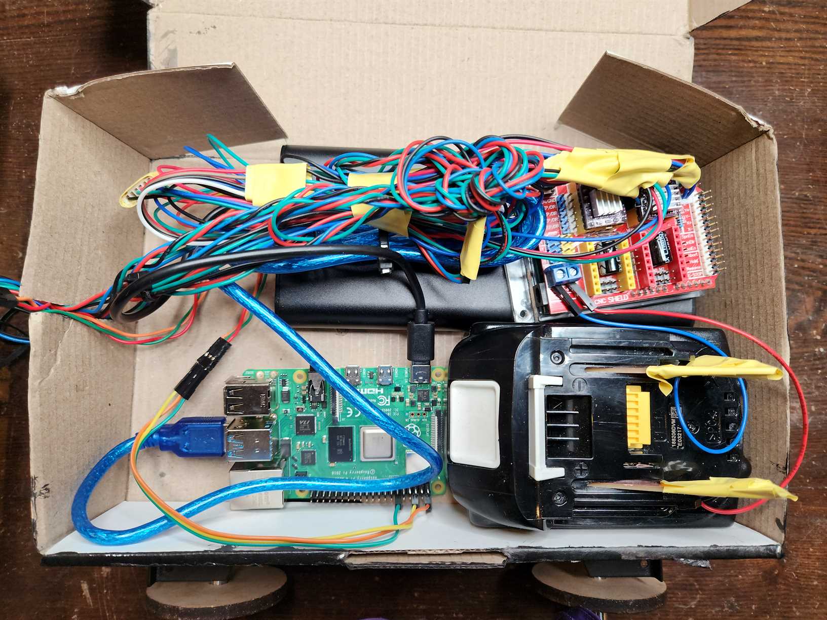
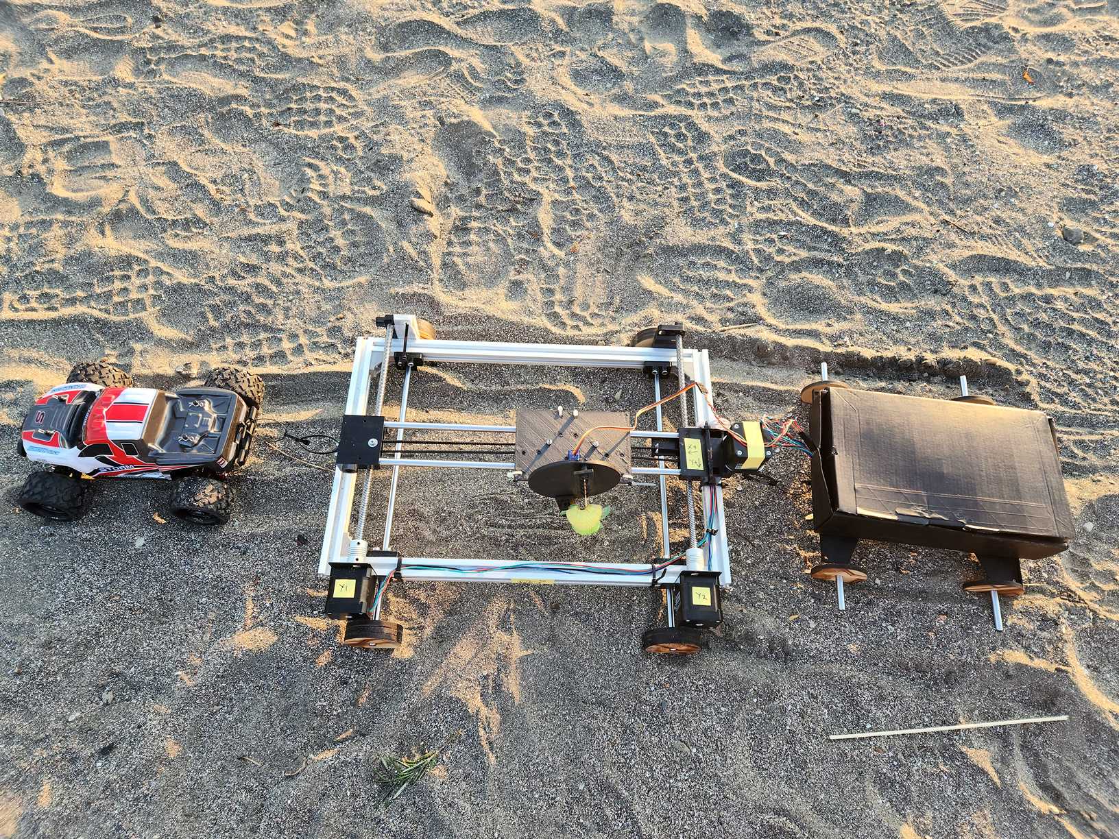
Final Electronics Setup
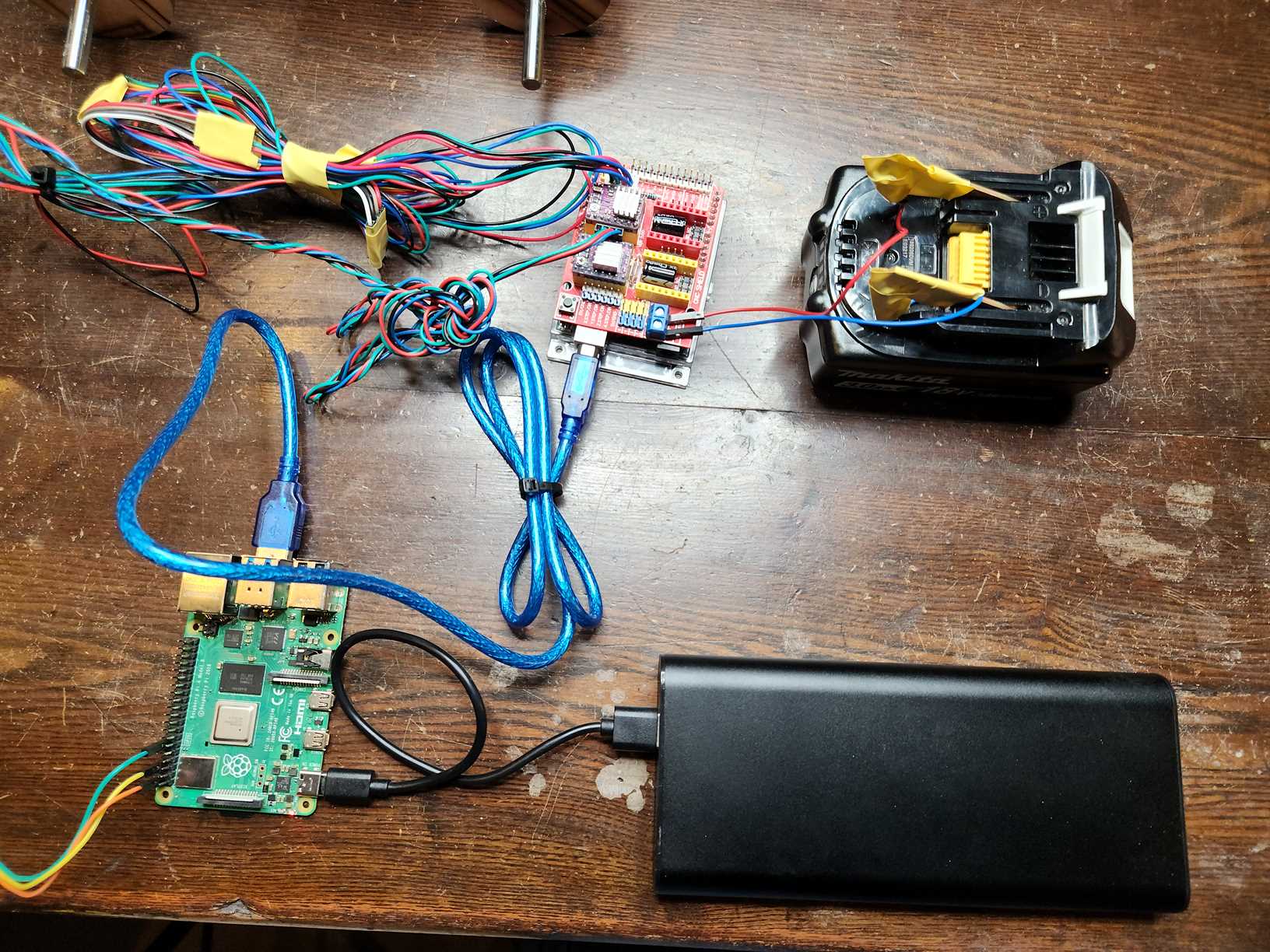
Electronics in the cart to be pulled behind the main machine.
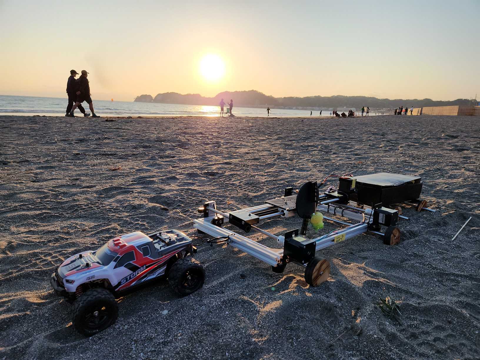
Final Machine in the Sand
Final Thoughts and Conclusions:
Overall we were happy with the concept and the outcome. Of course no-one is ever perfectly happy. And we absolutely plan to remake the machine again after the FabAcademy in a more sleek and complete form.
There were problems with the actuator and Kat would like to design a process in which in can create more defined lines in the sand. Whilst glitches are the purpose of the mechanism we would like the actual existence of them to be more defined, as it was a little disappointing when sometimes the actuator would bend too far and as a result not draw at all even though the machine as actually drawing shapes.
We would like to rebuild the machine and then maybe submit it to some media art festivals such as ArsElectronica as a thought-experiment on machine contracting.
But honestly the biggest thing we learned from this week was how well we work together, which is also why we are certain to return to this project again. Those were fun weeks brainstorming together and coming up with wait to turn the brief on it’s head.