13. Input devices
Individual assignment:
- Measure something: add a sensor to a microcontroller board that you have designed and read it
Group assignment:
- Probe an input device’s analog levels and digital signals
A. INDIVIDUAL ASSIGMENT
- A wide variety of sensors and/or transducers are available for all areas.
-
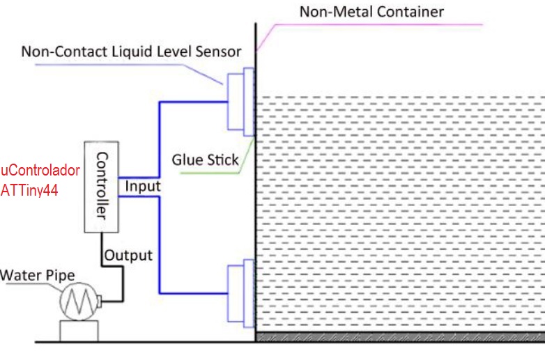
My final project is to measure the liquid level using a non-contact capacitive sensor. I decided to test this water level sensor with the board I designed the previous assignment. My board uses the ATTiny44 microcontroller.
-
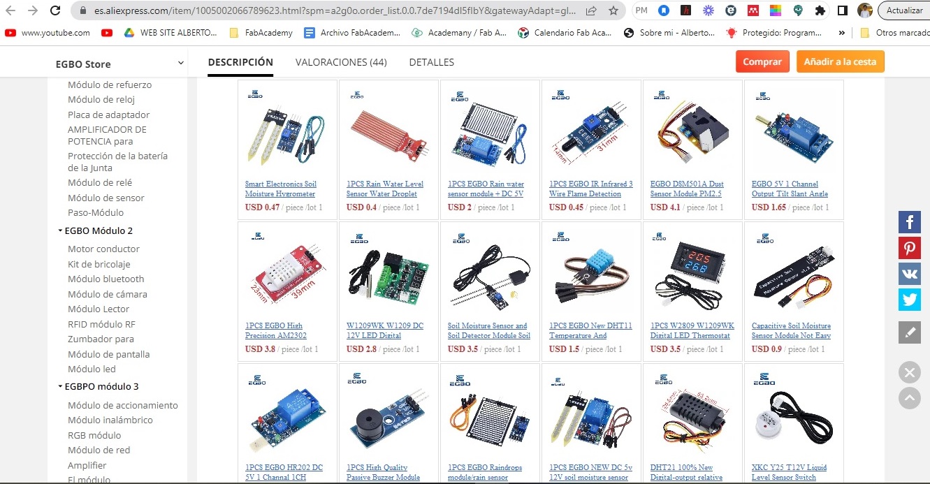
As in my Fablab we do not have this type of sensor, I ordered it weeks before from Aliexpress. Here are some pictures of the arrival.
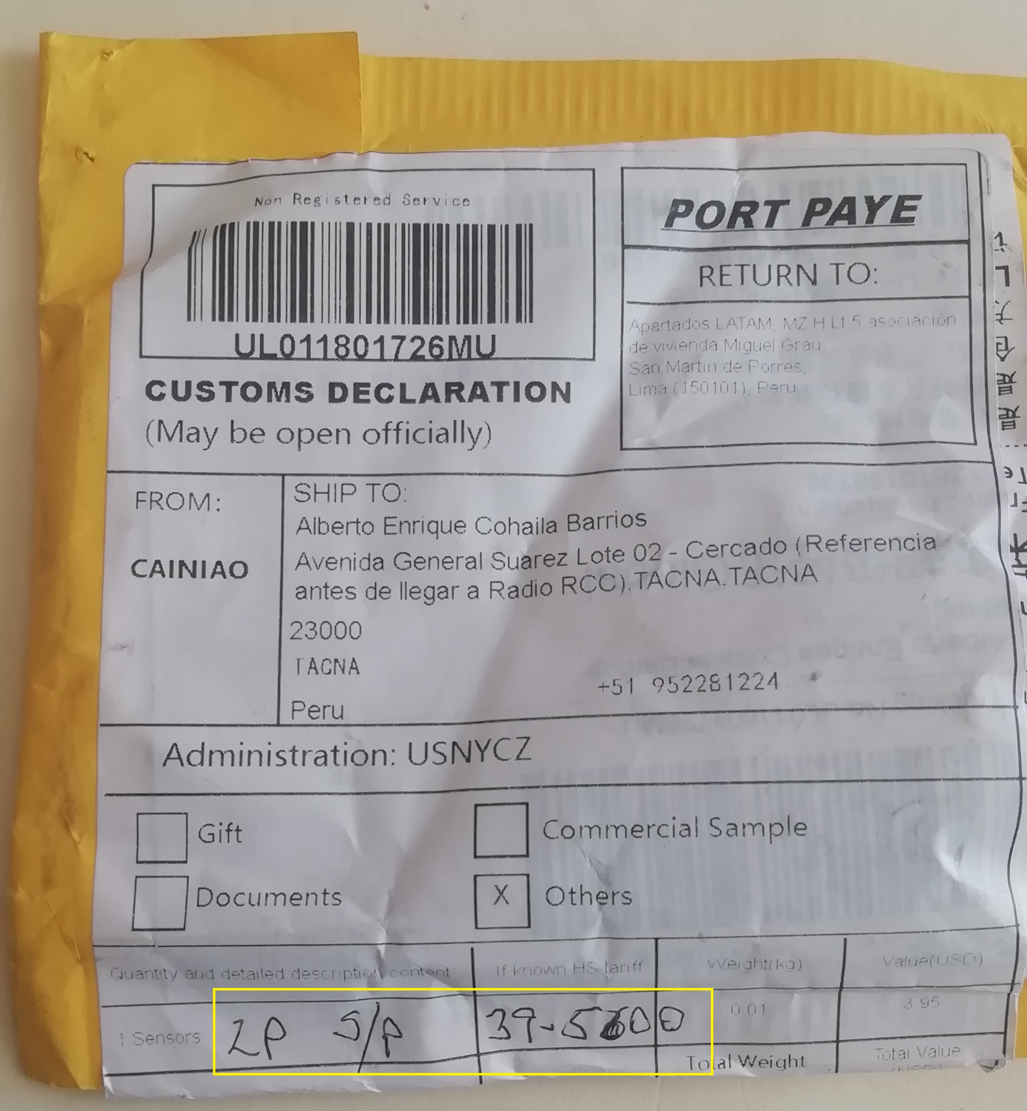
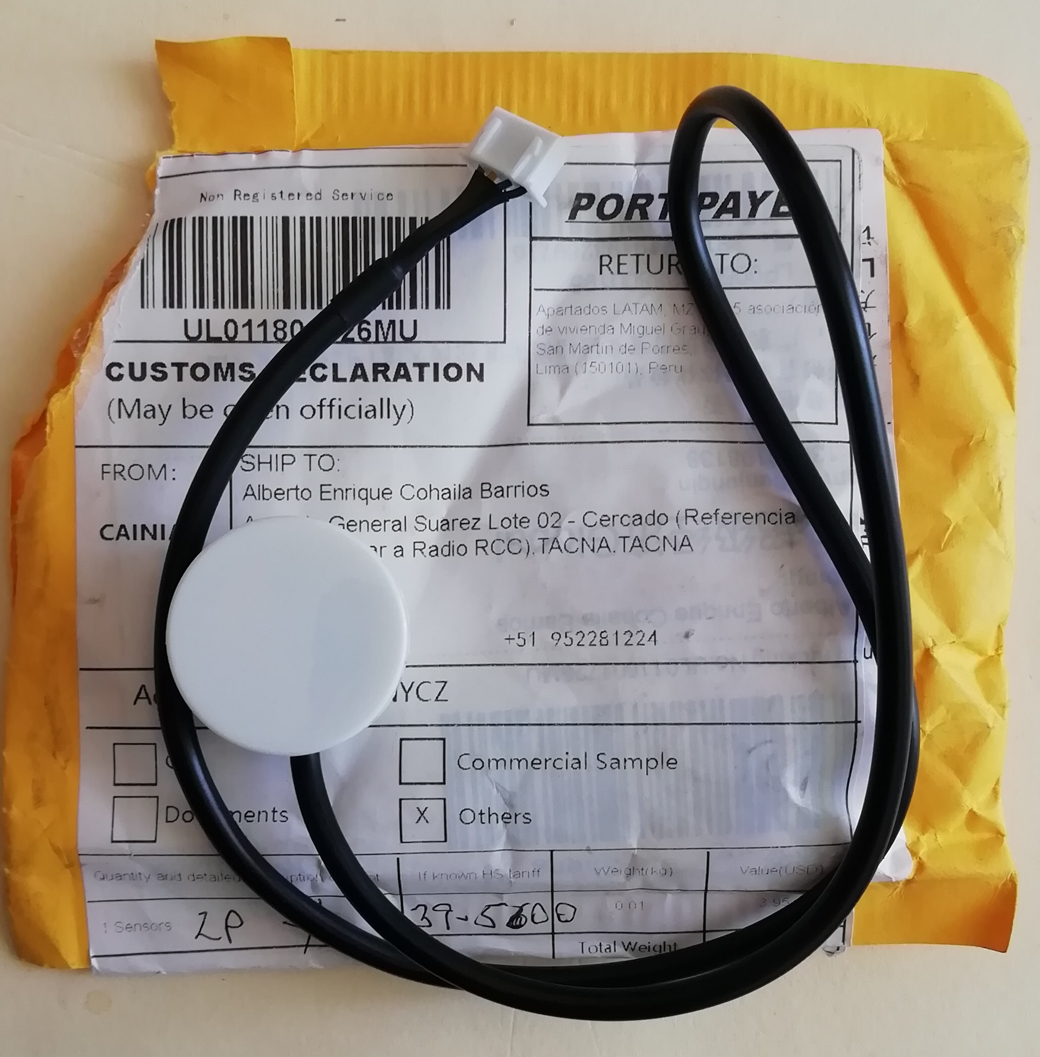
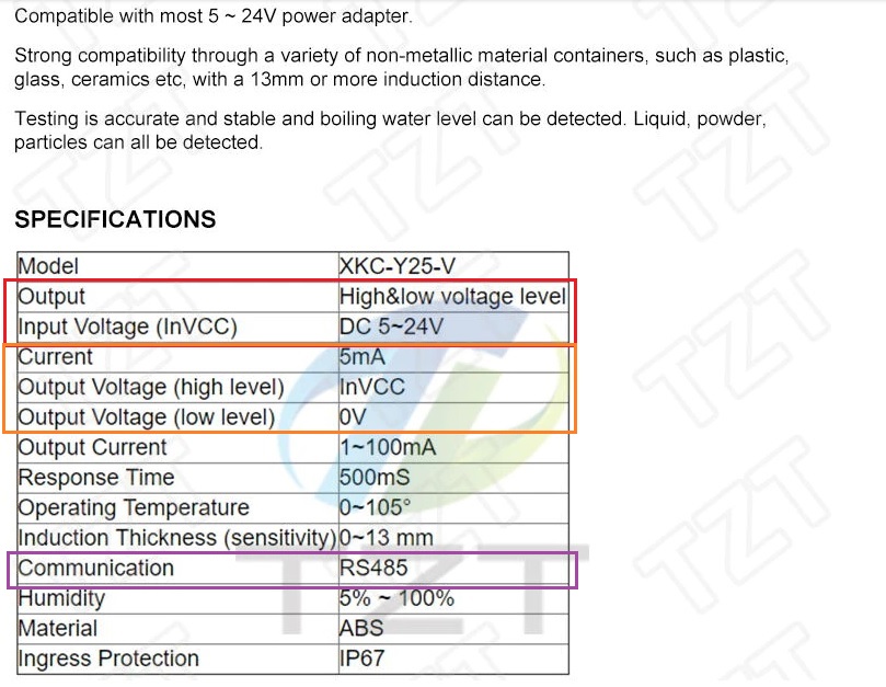
Liquid Level Sensor XKC Y25 T12V
- This is the manufacturer’s information:
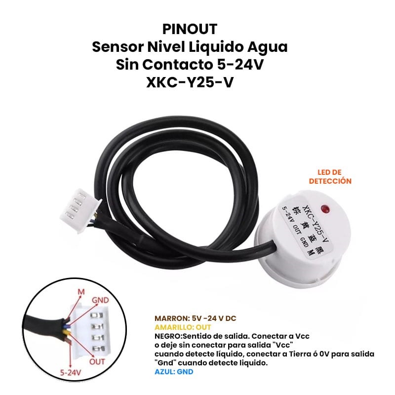
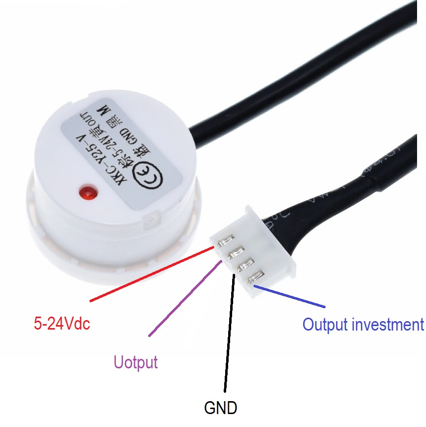
- Pinout descriptions:
- The application will be for liquid level detection of a tank or vessel. The signal must be read by the ATTiny 44A and alert by means of a LED or LCD display an alarm signal.
First test with ATMega328P
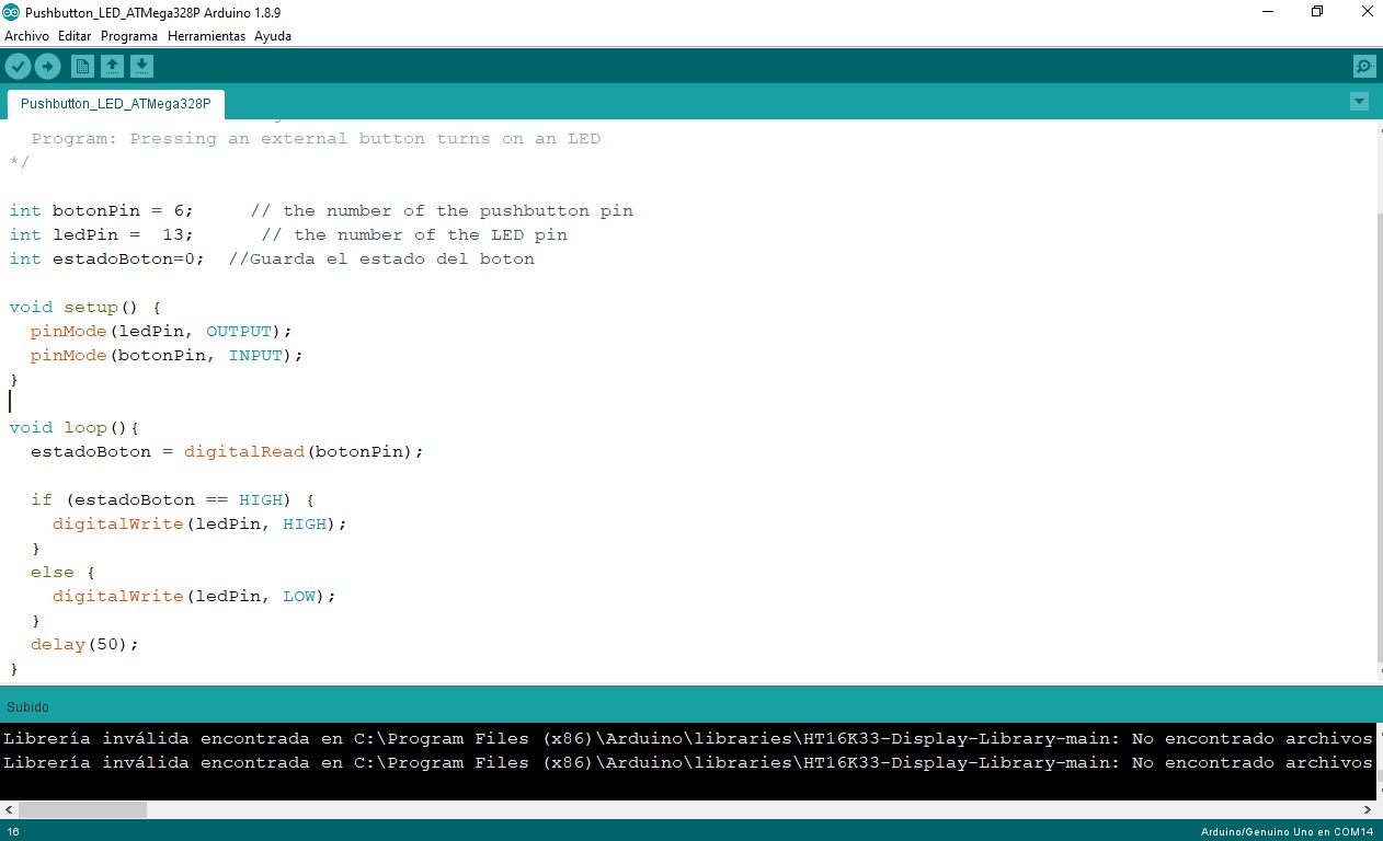
- Code: Use the code from the previous mapping (embedded programming) pushbutton.ino. The sensor signal is read on pin6, when it detects water it should turn on the internal LED (pin13) of the Arduino. This is the first code:
/int botonPin = 6;     // Signal of sensor level --> pin 6
int ledPin =  13;     // the number of the LED pin
int estadoBoton=0;    //Guarda el estado del boton

void setup() {
  pinMode(ledPin, OUTPUT);
  pinMode(botonPin, INPUT);
}

void loop(){
  estadoBoton = digitalRead(botonPin);

  if (estadoBoton == HIGH) {
    digitalWrite(ledPin, HIGH);
  }
  else {
    digitalWrite(ledPin, LOW);
  }
  delay(50);
}
- I transfer to the Arduino and test. Here is a video:
- The LED lights up when water is detected.
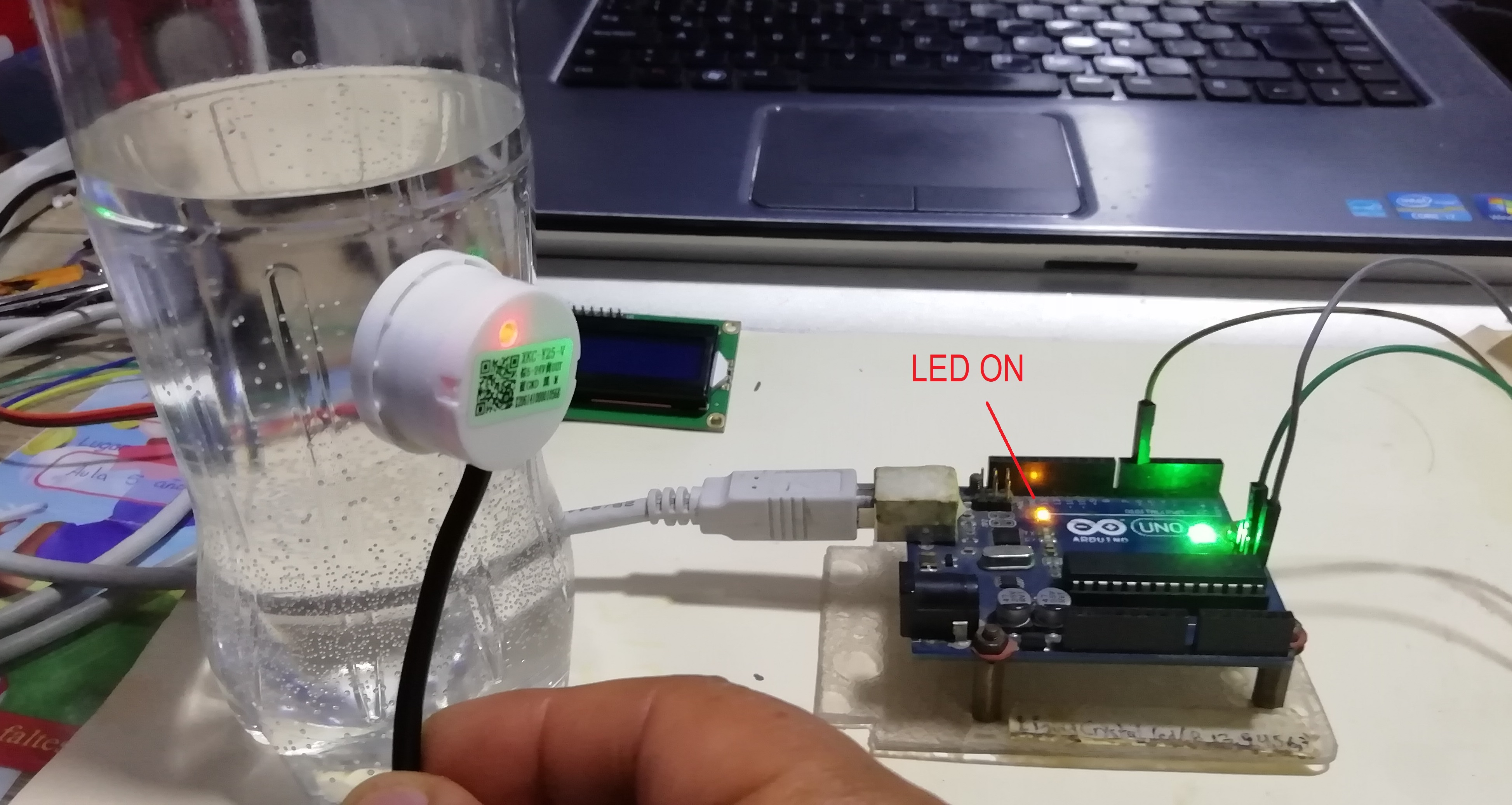
- Watch a video here.
-
Now I add the LCD display via I2C communication to the arduino. This way I generate a warning text.
-
Modify the code from Week 09. Embedded programming, LCD_I2C_Arduino.ino and add the LED that turns on when it detects water from the bottle. The coding is as follows:
/* Water Level Detector
   Sensor: XKC-Y25-V
   The LED lights up when water is detected. LCD display sends a text warning.
   Pinout:
   Sensor --> Arduino
   Signal --> pin6
   -------LCD---------
   SDA    --> A4
   SCL    --> A5
*/
#include <LiquidCrystal_I2C.h>
LiquidCrystal_I2C lcd(0x3F, 16, 2);

int sensorPin = 6;    // Signal of sensor level --> pin 6
int ledPin =  13;     // The number of the LED pin
int estadoSensor=0;   // Guarda el estado del boton

void setup() {
  lcd.init();
  lcd.backlight();    //Turn on the backlight
  lcd.setCursor(0, 0);             // Go to column 0, row 0
  lcd.print("Water Level Sensor");
  pinMode(ledPin, OUTPUT);
  pinMode(sensorPin, INPUT);
}

void loop() {
  estadoSensor = digitalRead(sensorPin);
  lcd.setCursor (0, 1);
  if (estadoSensor == HIGH) {
    digitalWrite(ledPin, HIGH);
    lcd.print("With water   ");
  }
  else {
    digitalWrite(ledPin, LOW);
    lcd.print("Without water");
  }
  delay(10);
}
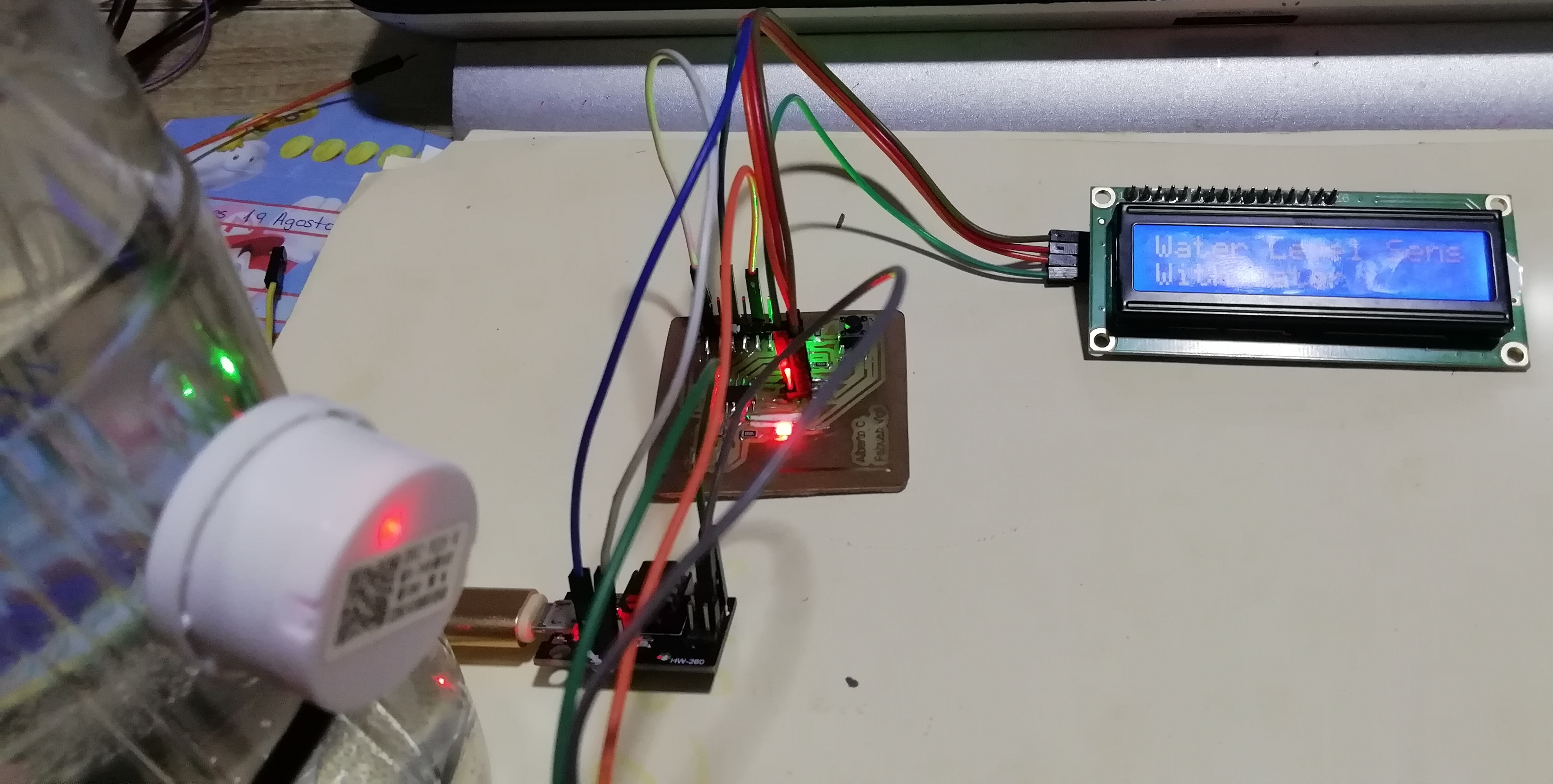
- This is how I made the connections, everything ok:
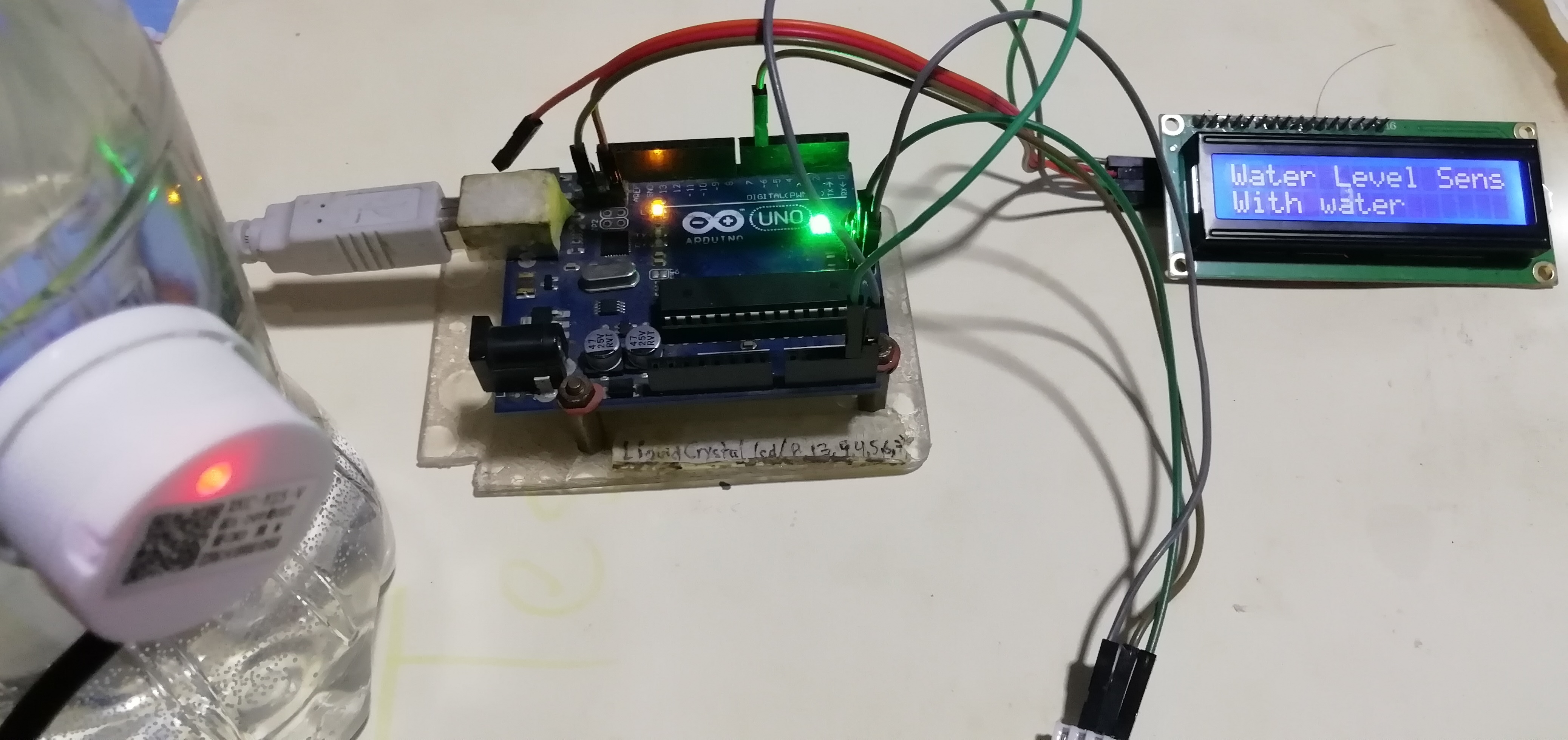
- Let’s see the final solution in the second video:
Second test with my ATTiny44A board
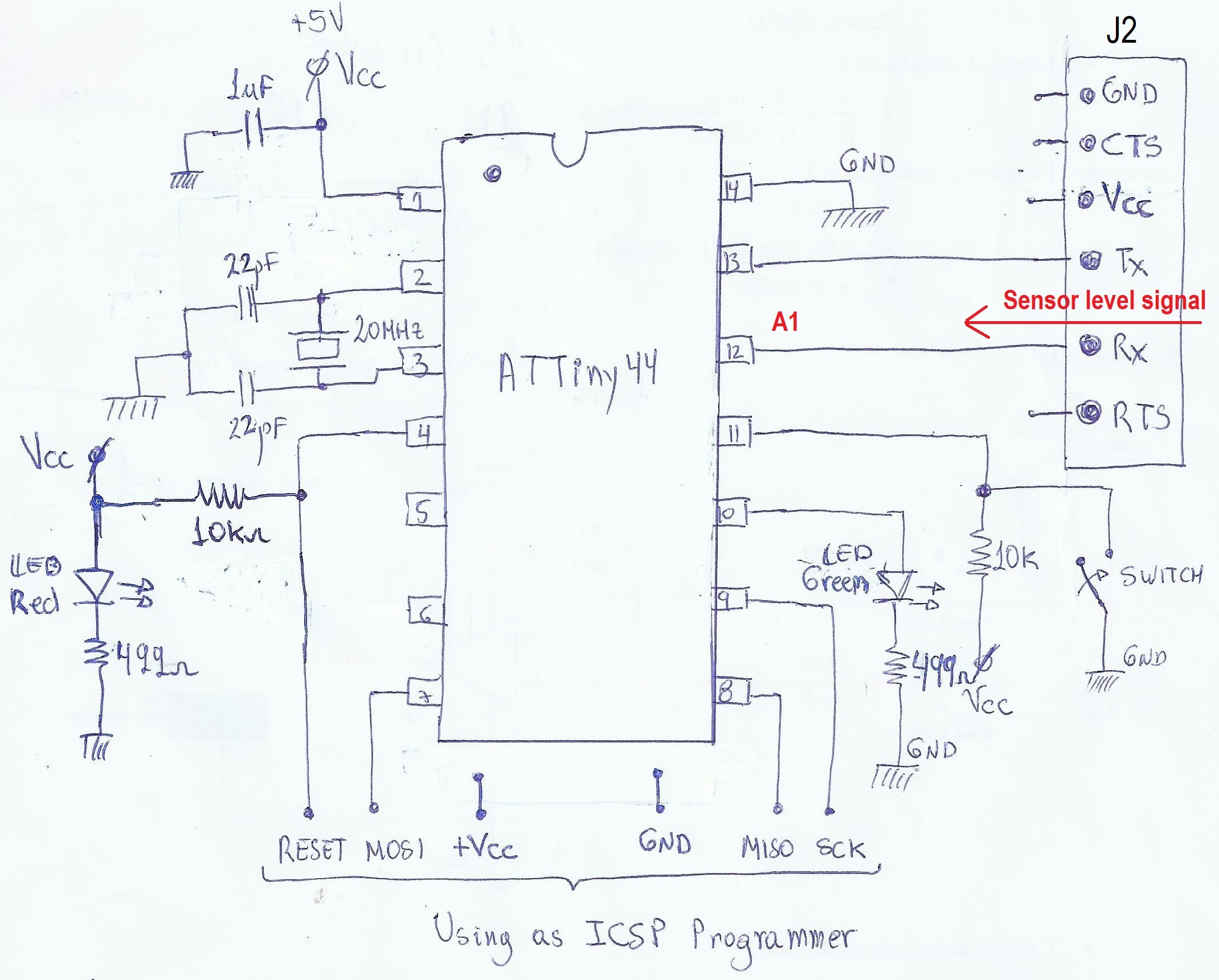
- I remembered that jumper J2 (FTDI), on my board, uses one pin for Tx and the other for Rx external signal. I decided to use the Rx pin (pin12) where the signal from the water level sensor enters.
- Now I am going to connect the USBTinyISP with the HelloATTiny44A board that was manufactured in week 7. Electronic design
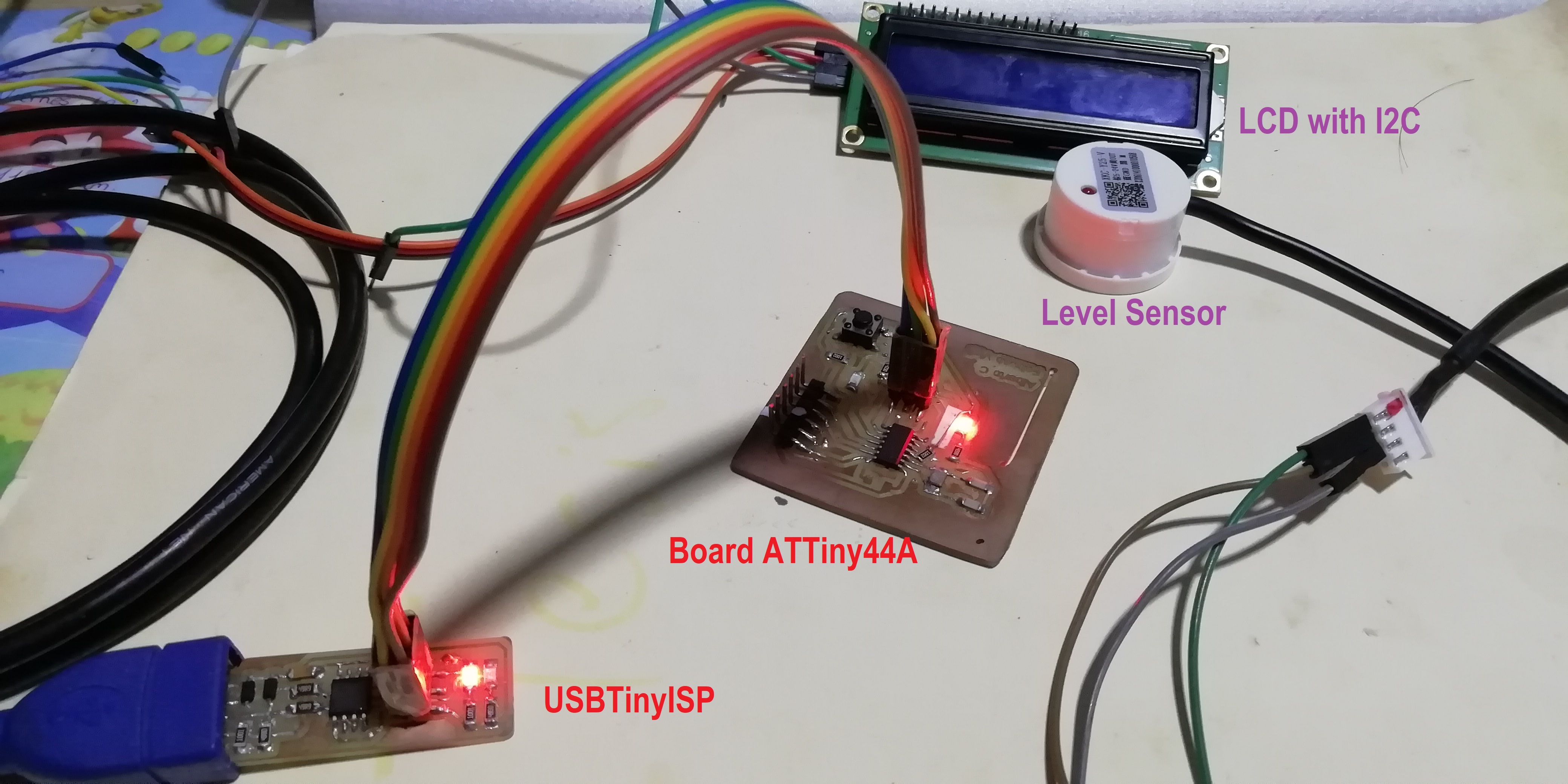
-
The USBTinyISP programmer board was manufactured in week 5. Electronics production
-
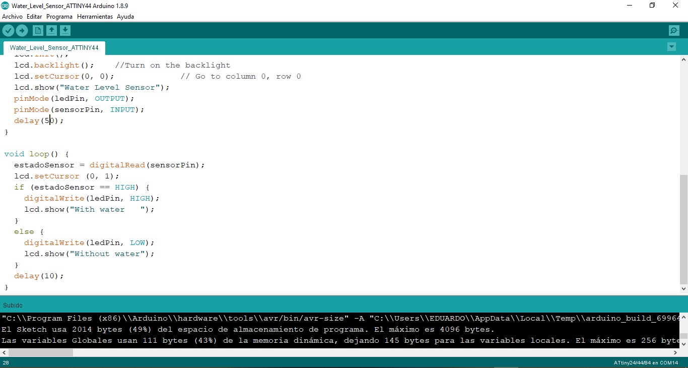
Modify the above program to address the ATTiny44 pins.
- What complications did I have here? I remember here that the lcd.show recognized the ATTiny44A unlike the print.show of the ATTmega328P. I solved the problem and was able to continue.
This is the result of the programming:
/*
   ATtiny44/84 I2C pins:
   ATtiny Pin 5 = SDA --> PB0
   ATtiny Pin 7 = SCK --> PB2
*/

// Water Level Sensor ATTiny44A

#include <TinyWireM.h>
#include <LiquidCrystal_attiny.h>

uint8_t  count   =   0;
#define  ADDR    0x3F

LiquidCrystal_I2C lcd(ADDR, 16, 2);

int sensorPin = 1;   // Signal of sensor level --> pin 1 (RX, FTDI)
int ledPin =  3;     // The number of the LED pin 3
int estadoSensor=0;

void setup() {
  lcd.init();
  lcd.backlight();    //Turn on the backlight
  lcd.setCursor(0, 0);             // Go to column 0, row 0
  lcd.show("Water Level Sensor");
  pinMode(ledPin, OUTPUT);
  pinMode(sensorPin, INPUT);
  delay(100);
}

void loop() {
  estadoSensor = digitalRead(sensorPin);
  lcd.setCursor (0, 1);
  if (estadoSensor == HIGH) {
    digitalWrite(ledPin, HIGH);
    lcd.show("With water   ");
  }
  else {
    digitalWrite(ledPin, LOW);
    lcd.show("Without water");
  }
  delay(10);
}
- I make the correct connections and see that everything is going well. This is the hero image of the PCB.
- Here you can see the hero video of my PCB.
- For the individual assignment use the Hello Attiny44 PCB designed in the assignment 7. Electronics design, i leave the link for more information.
B. Working in group
-
Testing the digital level of the level sensor arriving at the input device (board ATTiny44).
-
To measure use the Rigol DS1052E digital oscilloscope, to see how is the digital input that enters if it is perfect square or presents ripples.
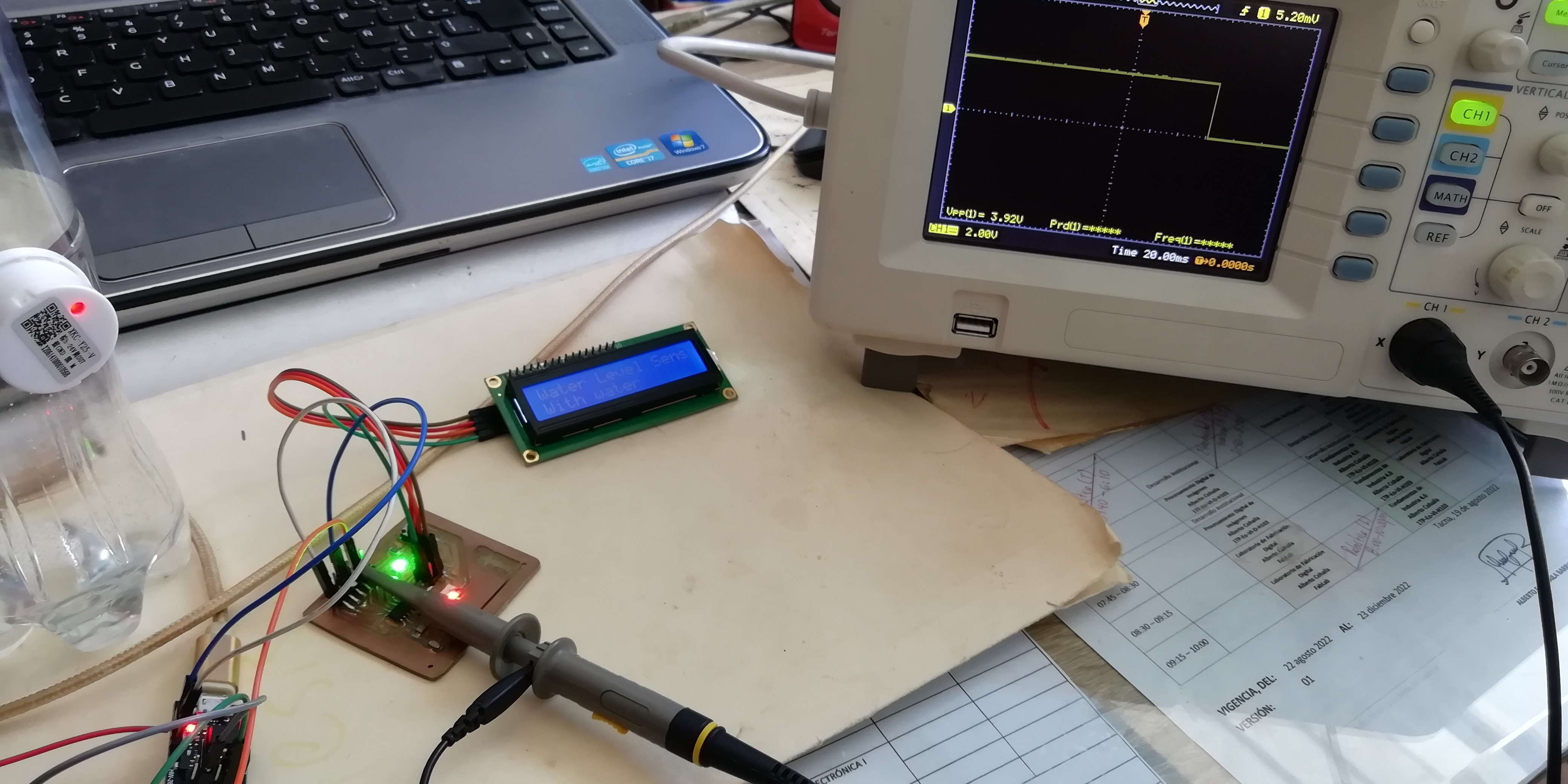
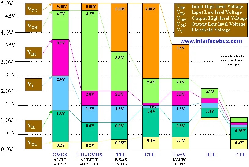
- The voltage level TTL of the digital pulses delivered by the level sensor, when it detects liquid, is 3.92 V. The AVR (ATTiny44/88) recognizes high logic level from 3.3 to 5 V.
- Here is a video:
Design Files
| Description | Files | |
|---|---|---|
| LevelSensor_LED | LevelSensor_LED.ino | |
| Water_level_sensor | Water_level_sensor.ino | |
| Water_Level_Sensor_ATTINY44 | Water_Level_Sensor_ATTINY44.ino |