7. Computer-Controlled Machining
CNC Tokamak Lamp
Group assignment:
- Complete your lab’s safety training
- Test runout, alignment, speeds, feeds, and toolpaths for your machine
- Link
Individual project:
- Make (design+mill+assemble) something big
Learning outcomes
* Demonstrate 2D design development for CNC production
* Describe workflows for CNC production
CNC Machine Introduction and Testing
For full documentation on machine testing please see our group site.
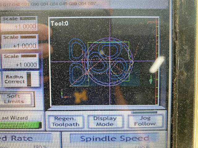
A Taiwanese local maker built this CNC mill for Fablab Taipei’s sister site “Tool Library” (工具圖書館). It’s fully DIY and has no brand. The laptop controlling it runs Artsoft Mach3 CNC Control software which reads G-code output from a CAM.
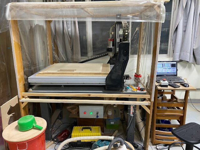
The total movement area of the CNC mill is 90x60cm. For the z-axis range, we didn’t measure it since it wasn’t an issue dealing with relatively thin 17mm boards. However, if I were to make an educated guess, it can probably move 20-30cm in height before hitting the upper limit (hitting the wood frame above).
For this week, we traveled to Tool Library multiple times to complete our CNC assignment. It is located in Wugu, New Taipei City and has much more space than Fablab Taipei because it’s outside the city in an industrial area. Over there, there are many more big machines for woodworking compared to our lab.
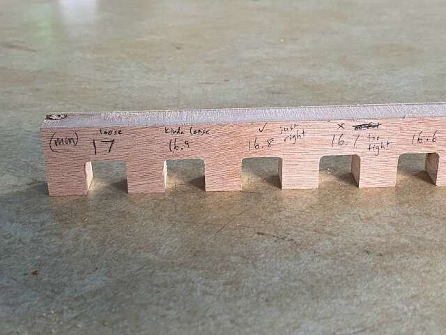
After safety training, the first test we did was to determine the tolerance we would need to set in order to achieve tight press fits for our project pieces using the plywood we had. We had two thicknesses, 8.5mm and 17mm and so we did two separate tests.
Similar to Week 3 with laser cutting, we used the joint clearance test comb generator. Since CNC mills required a CAM step unlike the laser cutter which could just take SVGs, we decided to keep everything in Fusion 360 for it’s CAD/CAM suite capabilities.
First, we imported the comb SVG to Fusion 360. The scaling was off so we had to manually scale and set dimensions. For us, the scaling factor was 3.77992440151197. Figuring this out took time, in hindsight it would’ve been faster to just draw new combs in Fusion 360 to begin with.
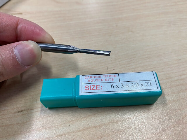
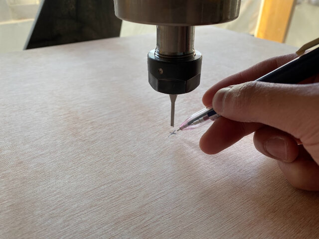
Then we could transition from Fusion 360 CAD workspace to CAM workspace. This is where we plan out exactly how the CNC machine will mill out the design from CAD. First we need to tell it what tool we’re using! This is it below, a carbide end mill that has a 6mm diameter shaft, a 3mm diameter cutting tip, 20mm length cutting tip, and has two flutes.
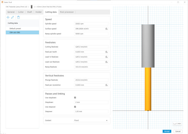
We input these specs into Fusion 360 CAM as a new tool and also designated the speed and feedrates settings. For the first test we used the conservative default speed of 12,000 RPM and feedrate of 1000mm/min. It worked just fine, but the machine could be pushed further. Using the CBA speed and feedrate calculator for OBS wood we calculated we could up the speed to 21,021 RPM and feedrate to 4267mm/min while having “Surface Speed” and “Chip Load” within the acceptable range. This made cutting a lot faster and the machine handled it just fine.
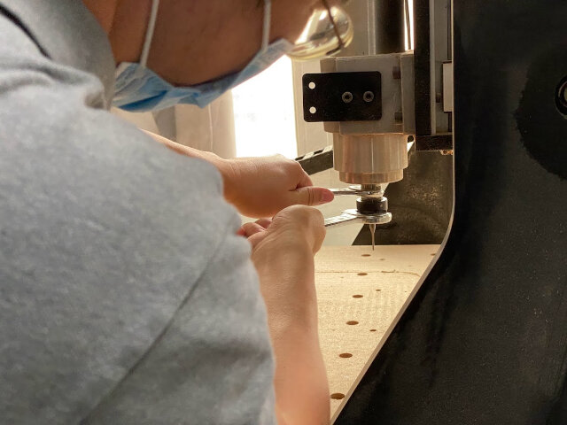
To set up the end mill, it needs to be placed into a collet, and then inserted into the CNC header, then tightened with 2 wrenches.
The 17mm board test comb showed an ideal tolerance is 0.2mm.

Set press fit widths to 16.8mm!
Inspiration / Brainstorming
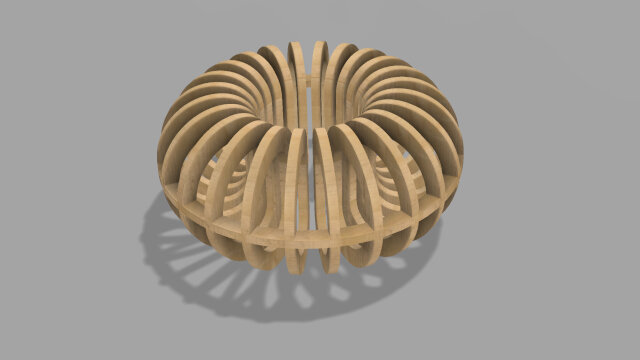
I’ve always liked interesting lighting features, so for this week I wanted to make my project a lamp fixture with interesting shapes that played with light. Sliced designs made with CNC look awesome, the way light passes through gaps can be mesmerizing!
In my research
https://fabacademy.org/2021/labs/waag/students/nadieh-bremer/blog/week-7/#fusion-360-with-the-python-api
Mobius strips are cool, start simple with donut
Part 2
Continuing to play with the idea of toroids (donuts)
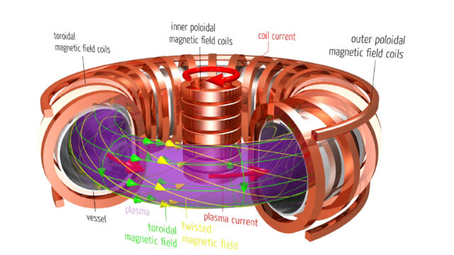
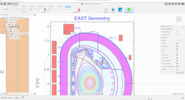
Tokamak fusion reactors are cool
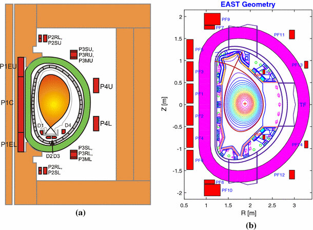
Plasma Magnetic Control in Tokamak Devices
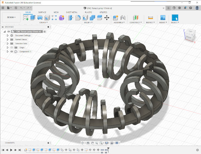
Design
Fusion slicer deprecated
Parametric design Thickness (ply) and tolerance
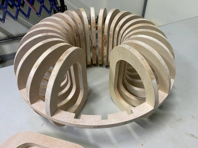
Spiral 1
Simple donut
Tried to economize on material with smaller slices inside bigger one. Ended up looking not that great.
Need more slices to look good. 24 not enough
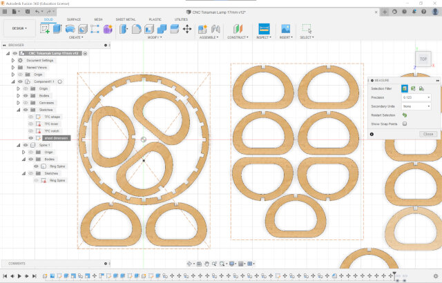
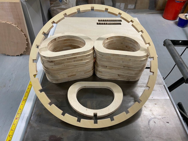
Spiral 2
Organic shapes for torus
Copied profile with spline
Ran into spline scaling issues https://forums.autodesk.com/t5/fusion-360-design-validate/spline-scaling/td-p/6655699
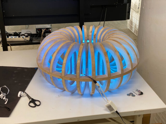
Tokamak Lamp final render
Designing for manufacturability
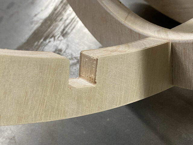
Dogbone
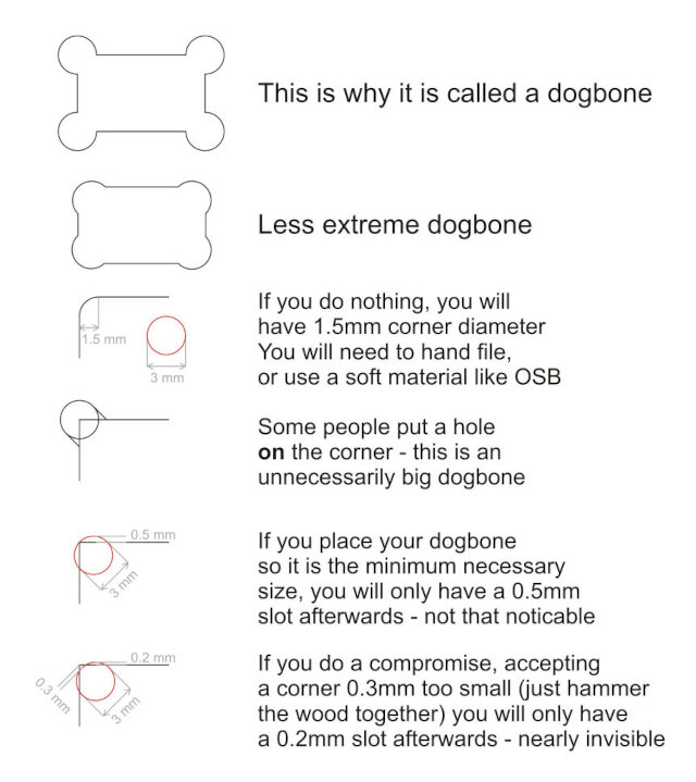
Credit: @pabzul
dogbone tool on github http://tapnair.github.io/Dogbone/
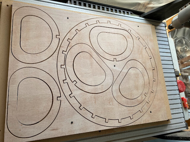
Milling and Assembly
Nesting https://www.youtube.com/watch?v=TIBMX-oVasU
Securing material down to CNC
The bottom layer is the sacrificial board.
Many ways to secure material onto the sacrificial layer, we used screws (regular metal ones). Avoid hitting them by previewing
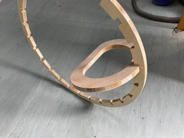
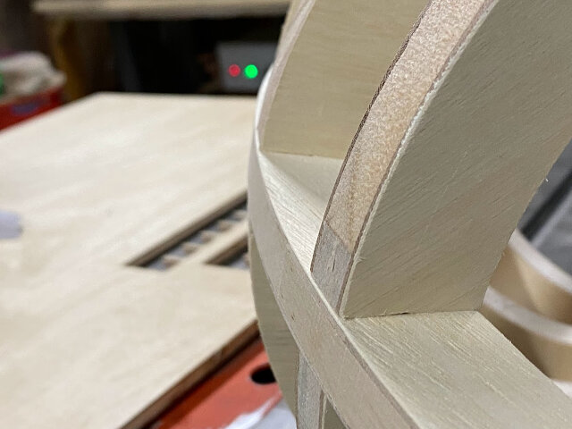
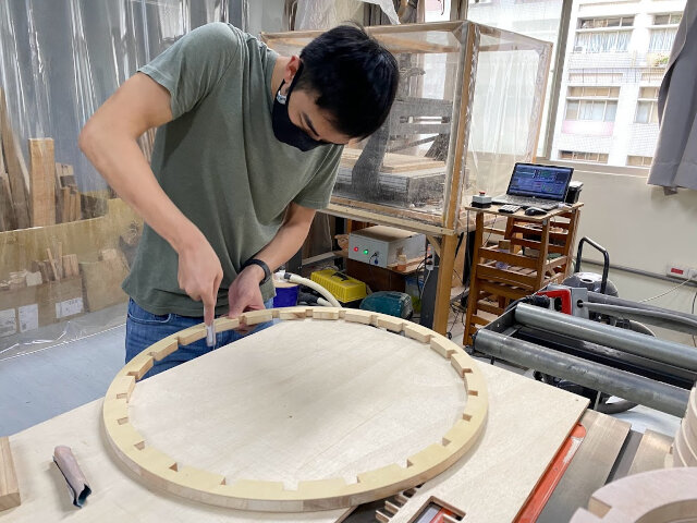
First Assembly
NOOOOO!!
Was I crazy?
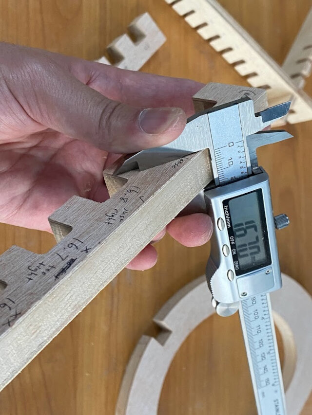
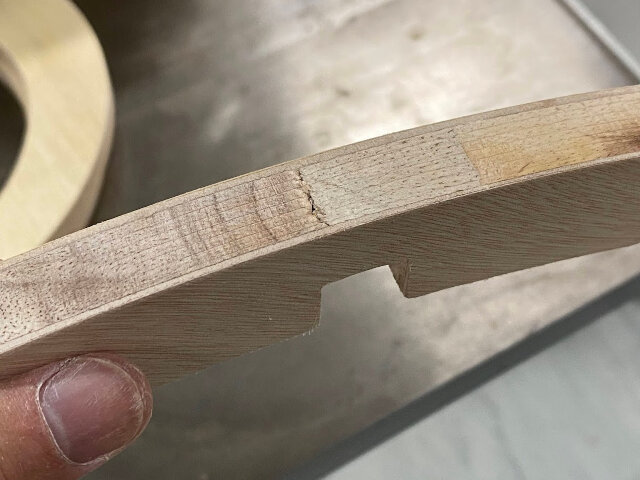
17mm press fit test comb unlucky, used thinnest board
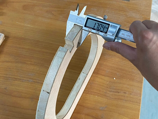
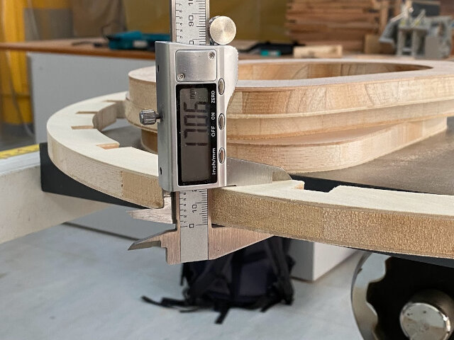
lumbercore 6 boards of 17mm 61 x 81 cm thickness variation 16.7-7.1mm variations present even in same board most common measurement was right around 17.0 mm though Redesign (again) with no tolerance Add chamfers to press fit notches Thankfully since I did parametric design, this can easily be done by changing just the tolerance parameter to zero
Cut out with burrs sanding a lot
TEARS

Third time’s the charm

// more documentation about machine controls
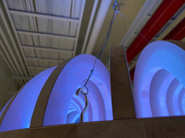
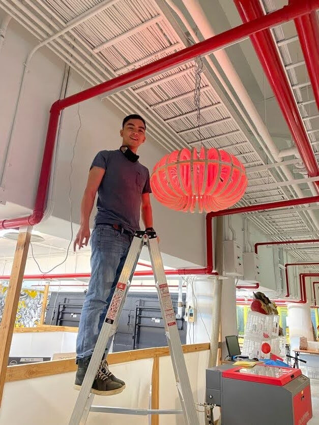
Hanging up in the lab
Eye hooks, steel wire #20 tied with Haywire Twist, chain link tied to ceiling beam.
Conclusion
Time taken whole thing took about 4.5 boards 1 board was about an hour each Sanding nearby while CNC milled
Future work / Want to try
- Test more cutting feeds and speeds to optimize finish
- Organic shapes/mathematical objects generated by scripting in Fusion 360 or Blender
- How to use Nest and Fabrication extension properly in Fusion 360
- Dogbone fillet automation tool in Fusion 360
Useful links
Design Files
- fusion file