5. Electronics production
Objectives
Group (To redirect to group assigment page Click here)
- characterize the design rules for your in-house PCB production process
- extra credit: send a PCB out to a board house
Individual
- make an in-circuit programmer that includes a microcontroller:
- extra credit: customize the design
- mill and stuff the PCB
- test it to verify that it works
- extra credit: try other PCB processes
Group
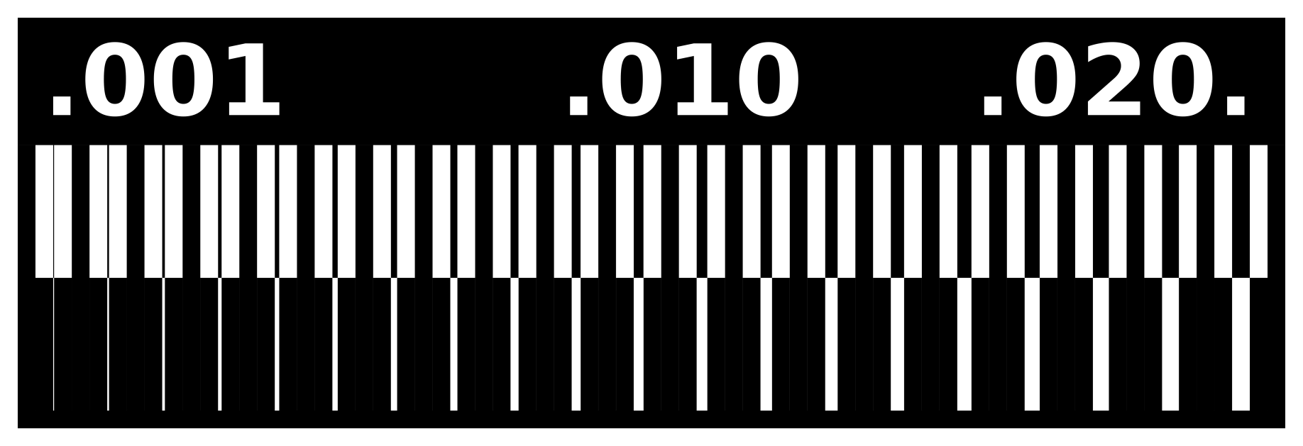
Resolution Test
It’s critical to determine the resolution of each bit before printing the in-circuit board. To do so, we used the file below to mill a FR1 board.
Setting up machine
If the bit is not 1/64, change it. Using an allen key, make sure the shank is kept as far inside the head as possible. Apply a double-sided adhesive sticker on the back of the board and paste it over the sacrificial layer.
Setting up and sending files via Mods
Select the machine from the landing page and upload the image in the Read Png node and select the mill traces(1/64) in Set PCB defaults node keeping the default settings click on calculate in mill raster 2D node make sure to orgin the tool head Rolend MDX/ iModelsclick send file in WebSocket pyserial after opening socket and open port.
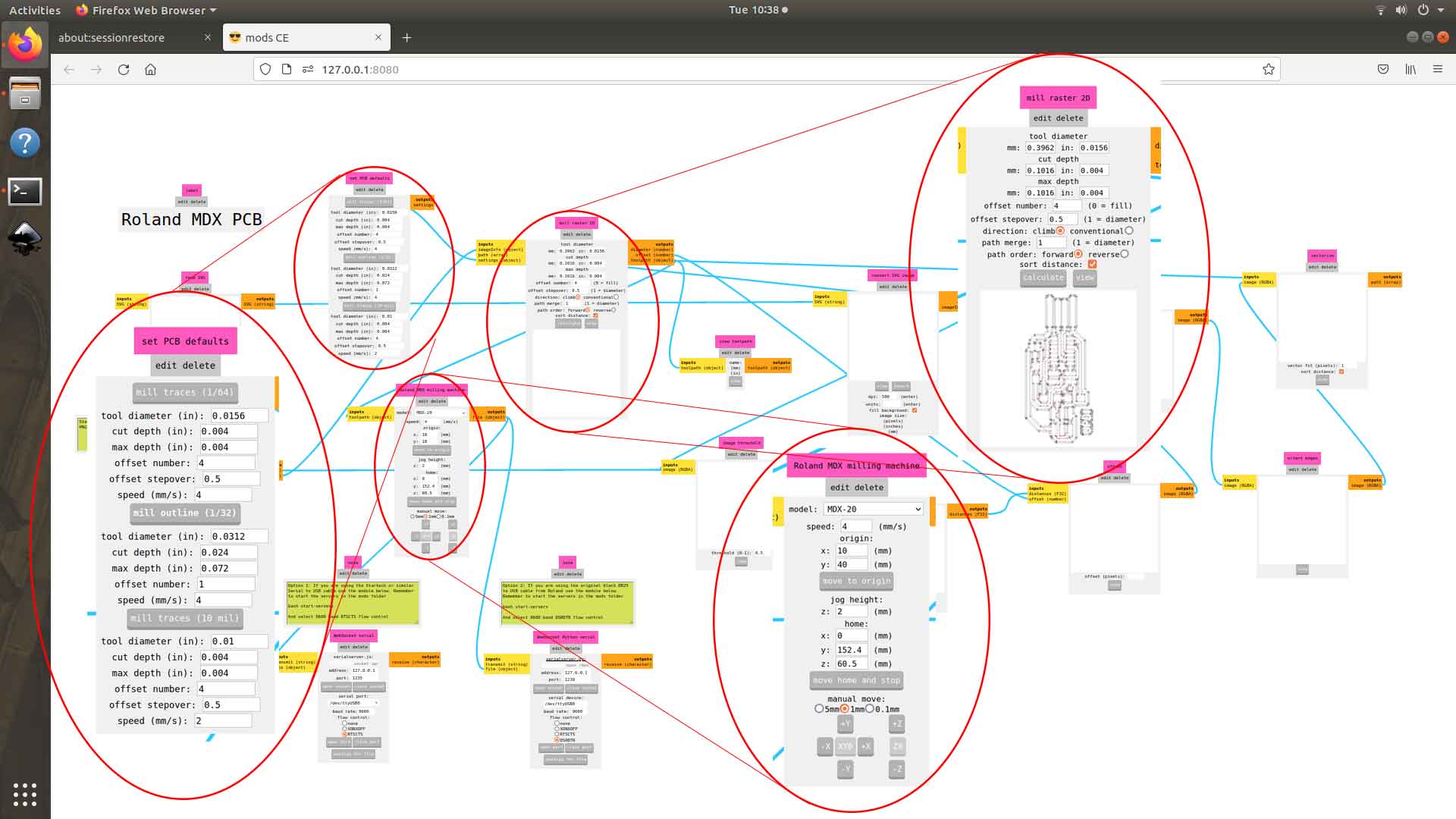
This initiate the milling process and the machine start to trace the PCB make sure thee bit inserted in the tool head is 1/64”
change the bit to (1/32) and import the outline png to cut the PCB out.
now repeat the same text using 1/32 bit and 1/10 bit
Group assigment results
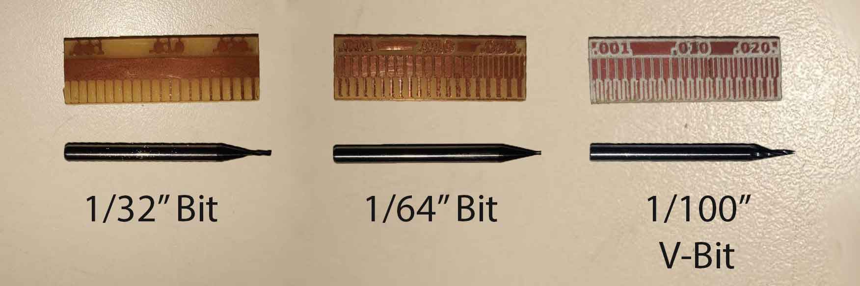
After the examination, we came to the conclusion that
- 1/64 bit
- speed: 6,500 rpm
- feed rate: 240 mm/min
- plunge rate: 0.004 in
- depth of cut: 0.004 in
- can trace upto 0.16 mm
-
1/32 bit
- speed : 6,500 rpm
- feed rate: 240 mm/min
- plunge rate: 0.024 in
- depth of cut: 0.072 in
- cannot be used to make traces better to use as a cutting tool
- speed : 6,500 rpm
- feed rate: 120 mm/min
- plunge rate: 0.004 in
- depth of cut: 0.004 in
- 1/10 bit can trace upto 0.11 mm
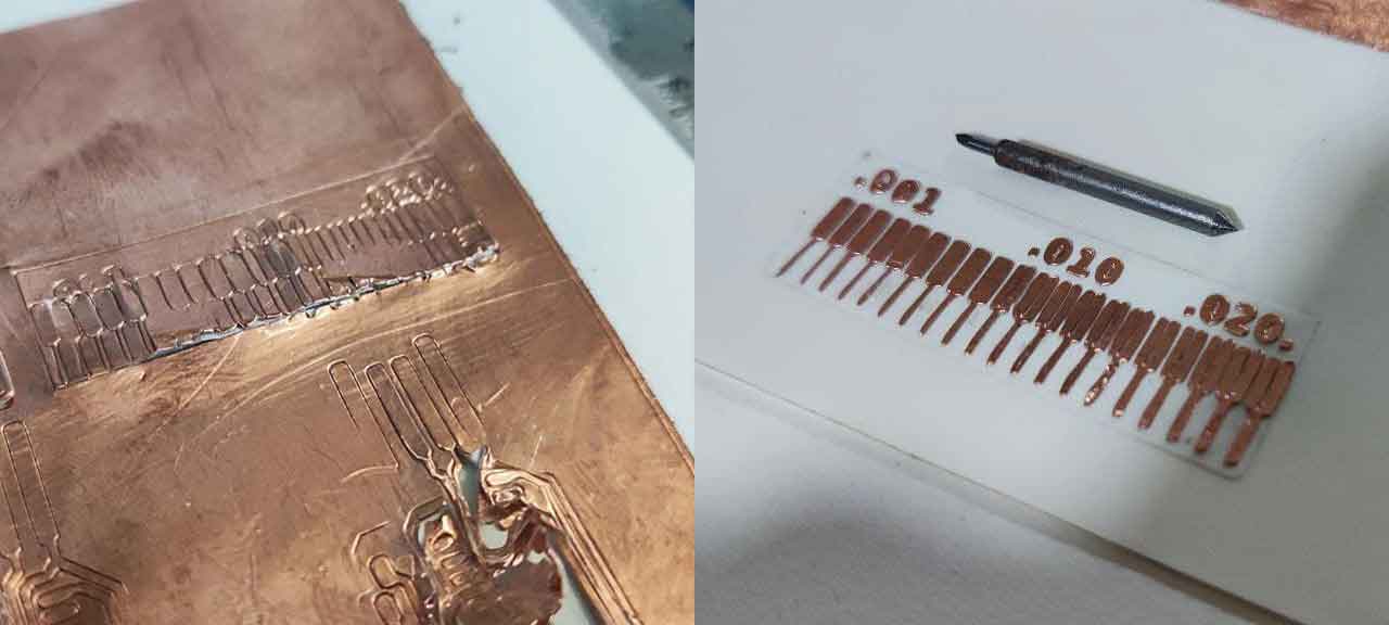
Other PCB processes
Uploaded the Line_Test file to CBA mods and traced the PCB on a flexible copper sheet using vinyl cutter
Milling the In-Circuit Programming
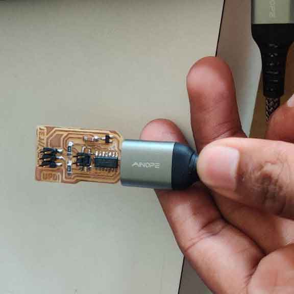
For making the UPDI programmer, I used the file from “https://gitlab.fabcloud.org/pub/programmers/programmer-updi-d11c”. A programmer is a device that allows a PC to communicate with an IC to upload information about how the IC should behave in the future.
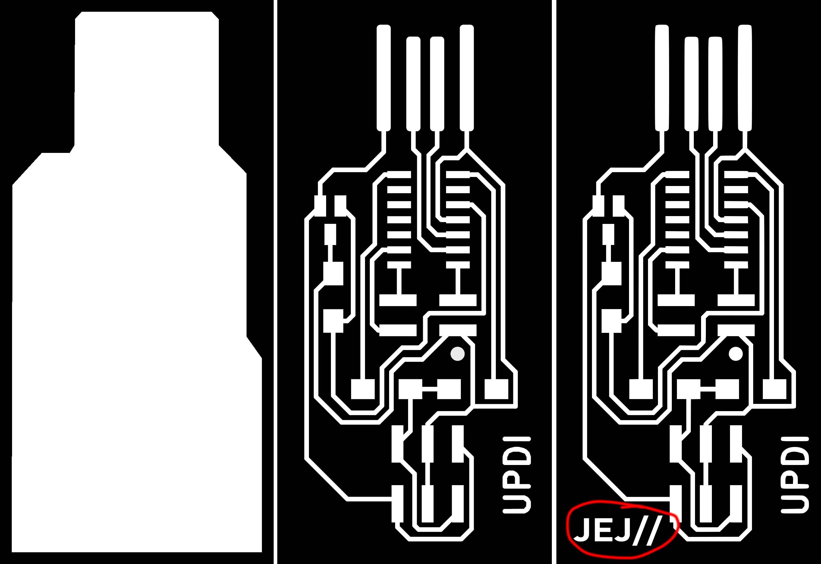
Inkscape was used to make a small modification to the PCB footprint by putting my initials to the bottom side.Using CBA Mods, the altered file was printed. The traces were made with a 1/64 bit, and the PCB was cut with a 1/32 bit. The machined output is next sandpapered for a clean finish and the connectivities are tested with a multimeter.
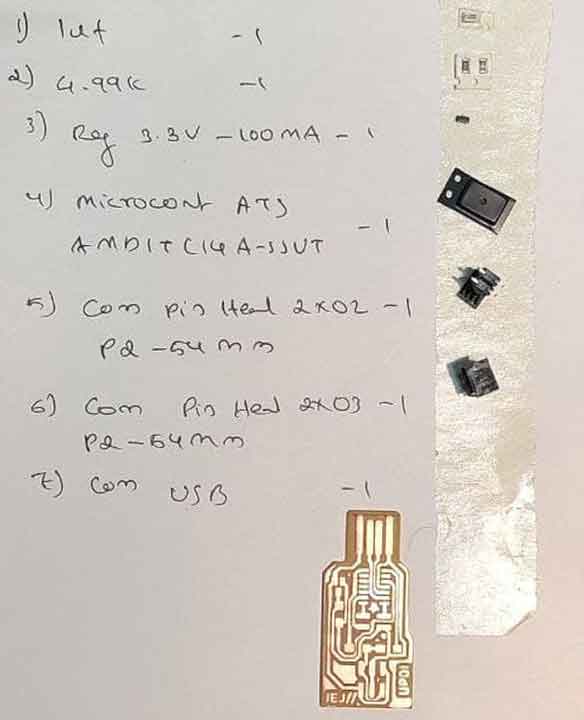
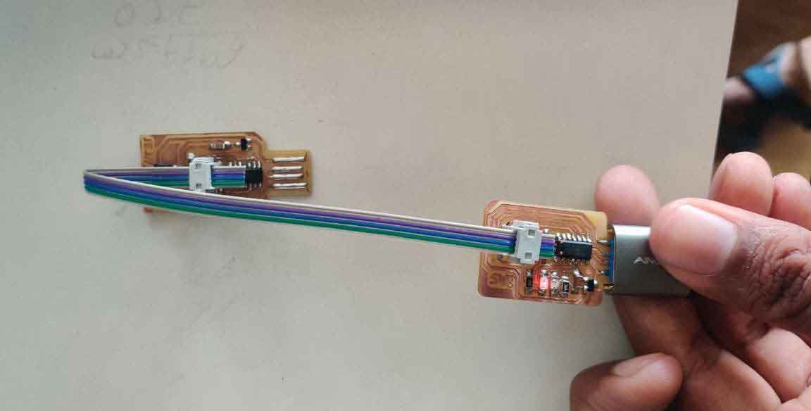
Stuffing & Soldering
Listed the required components for making the UPDI on a paper and collected the components from the fab inventory
heated the soldering iron to 360°C and soldered each components on to the board.
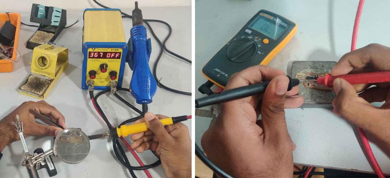
Using a multimeter, I ensured that there are no errors while soldering.
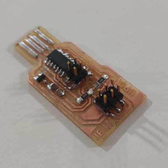
Testing & Programing
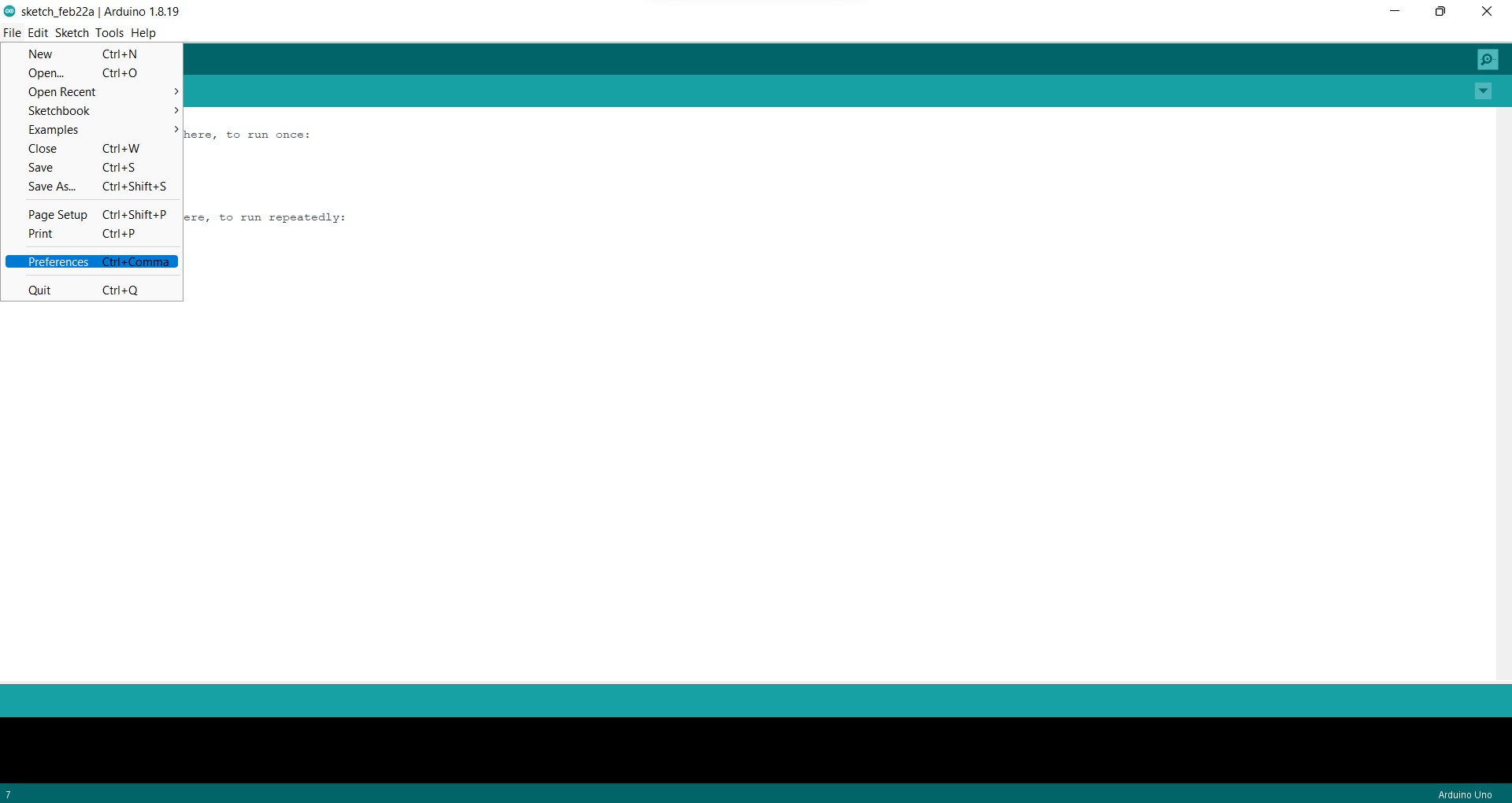
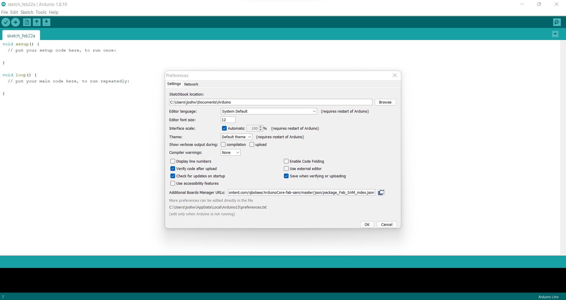
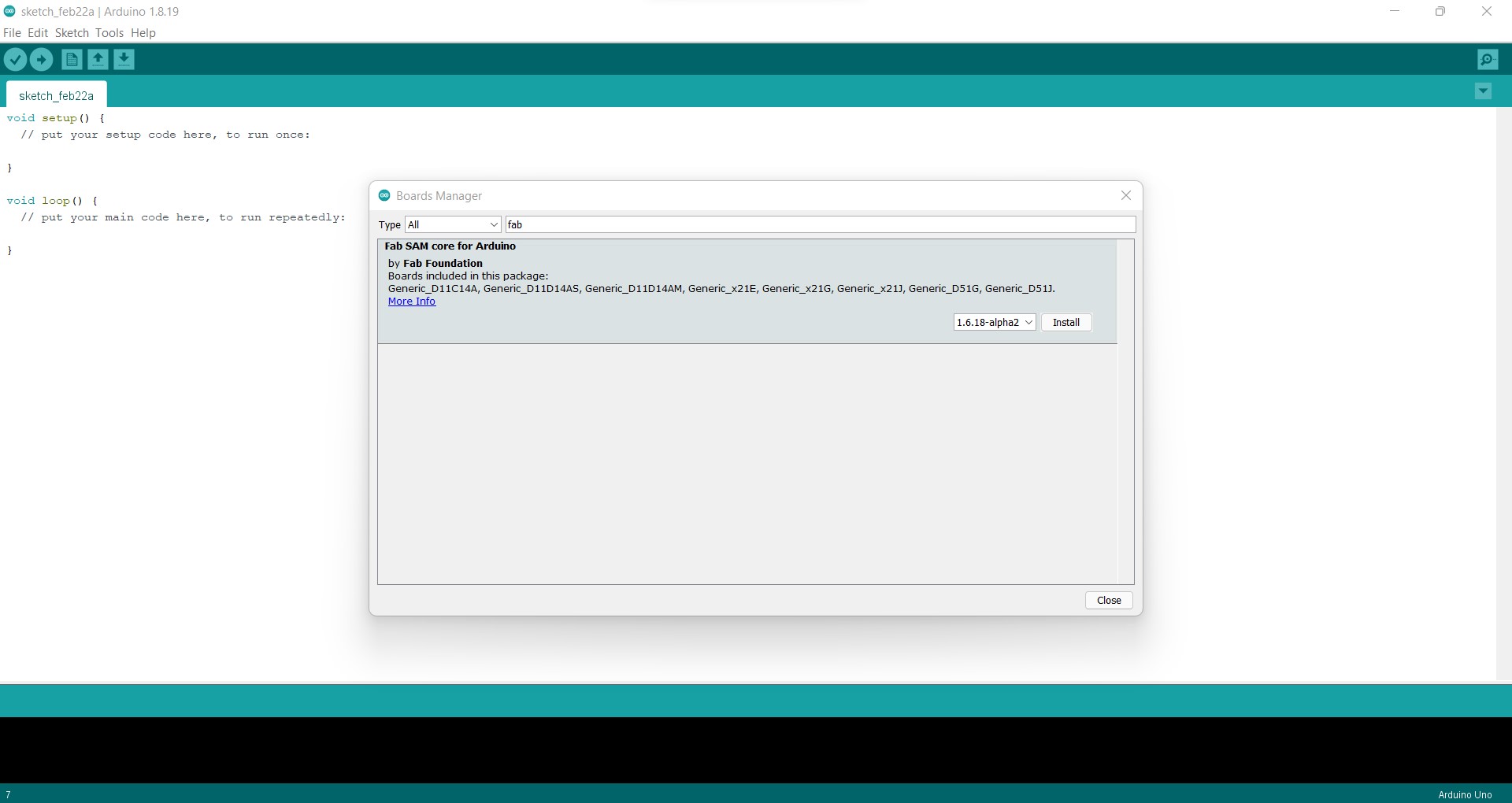
After I finished soldering the board, I used a multimeter to check for continuity. The boot loader for the UPDI to initiate USB communication was then uploaded using a SWD programmer using a aurdino IDE. To do so, go to Files > Preferences > Additional Boards Manager URLs > Paste the URL given below
https://raw.githubusercontent.com/qbolsee/ArduinoCore-fab-sam/master/json/package_Fab_SAM_index.json
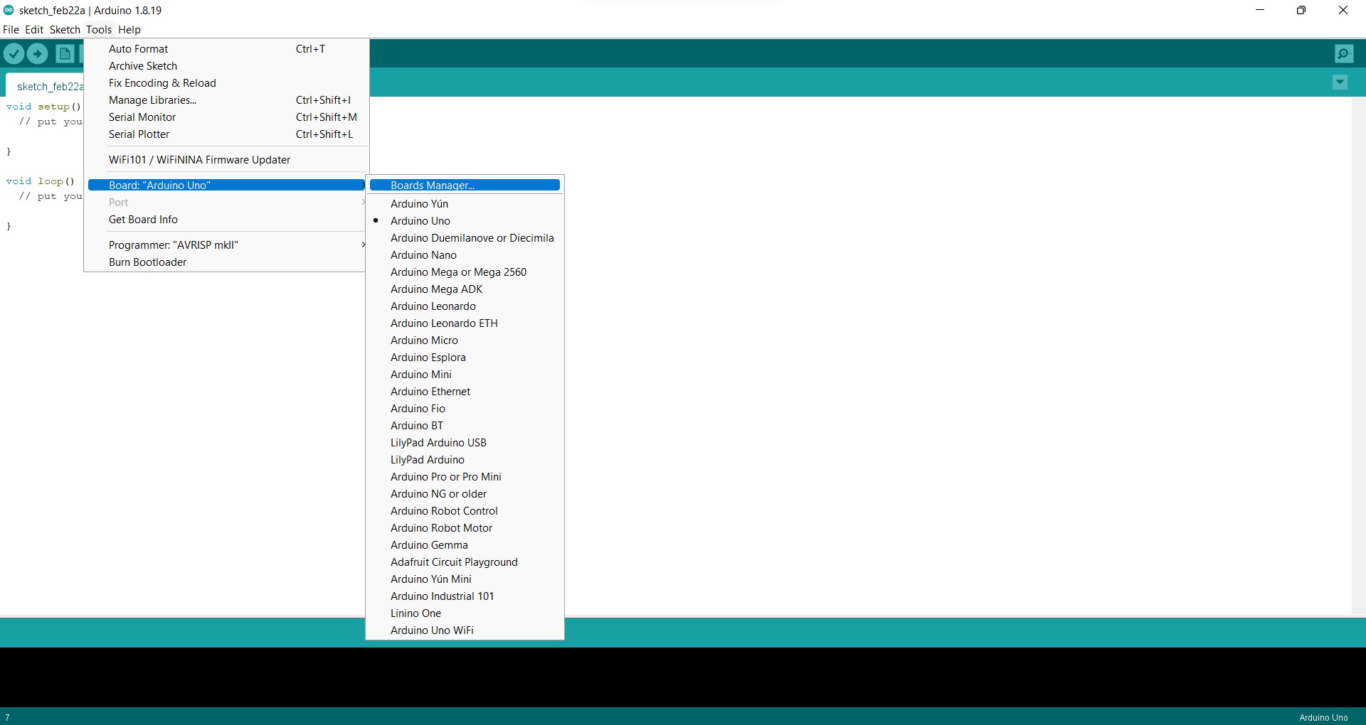
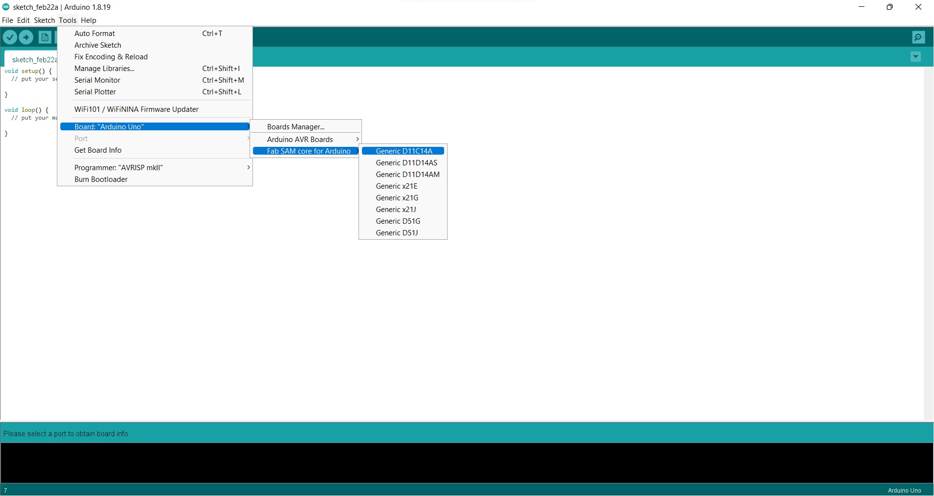
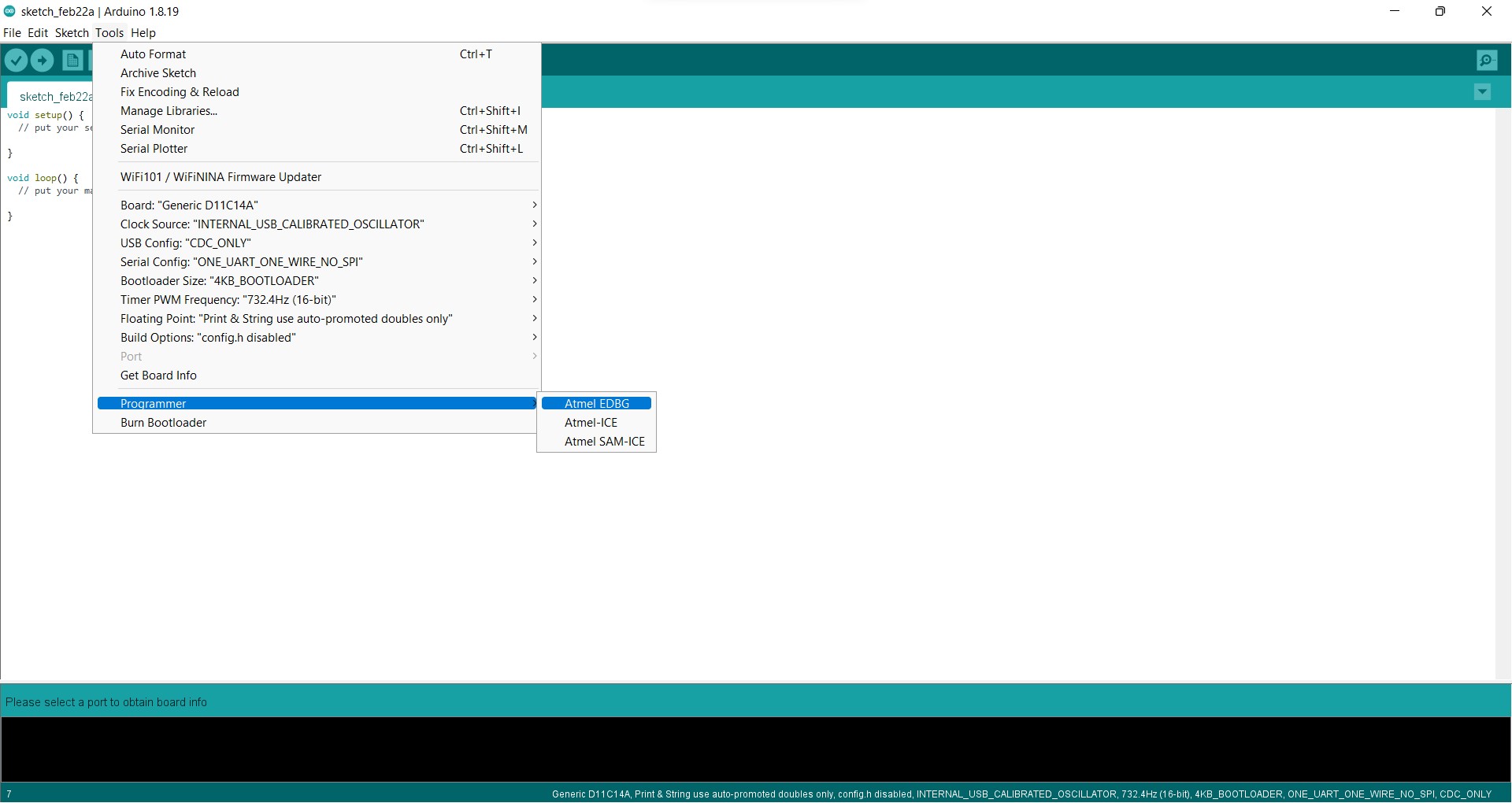
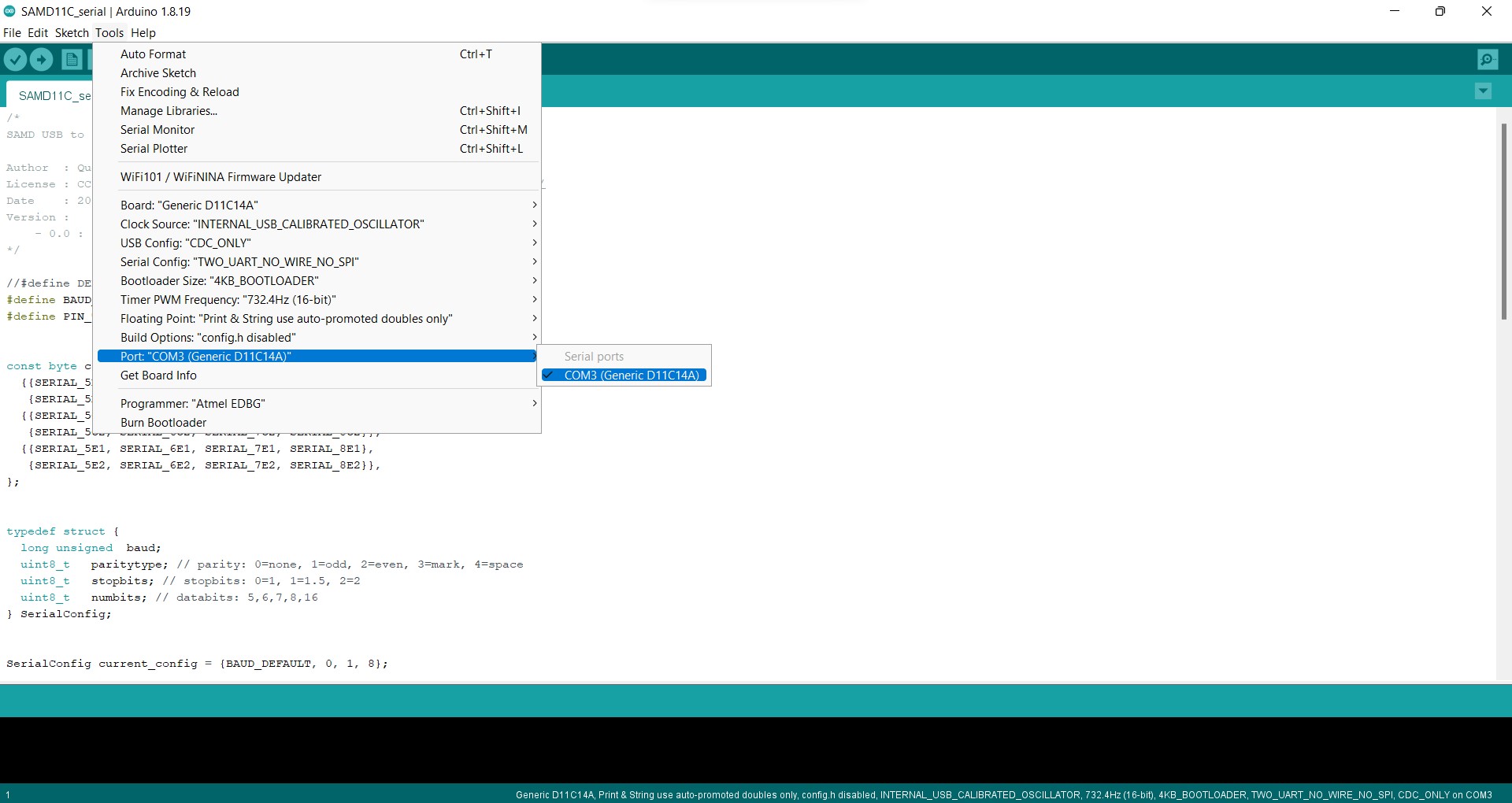
Then, from Tools > Boards: “xxxx” > Board Manager I downloaded the Fab SAM core for Aurdino. Now, after changing Board: “xxx” to Board: “Generic D11C14A” and Programmer to Atmel EDBG, simply click on Burn Bootloader.
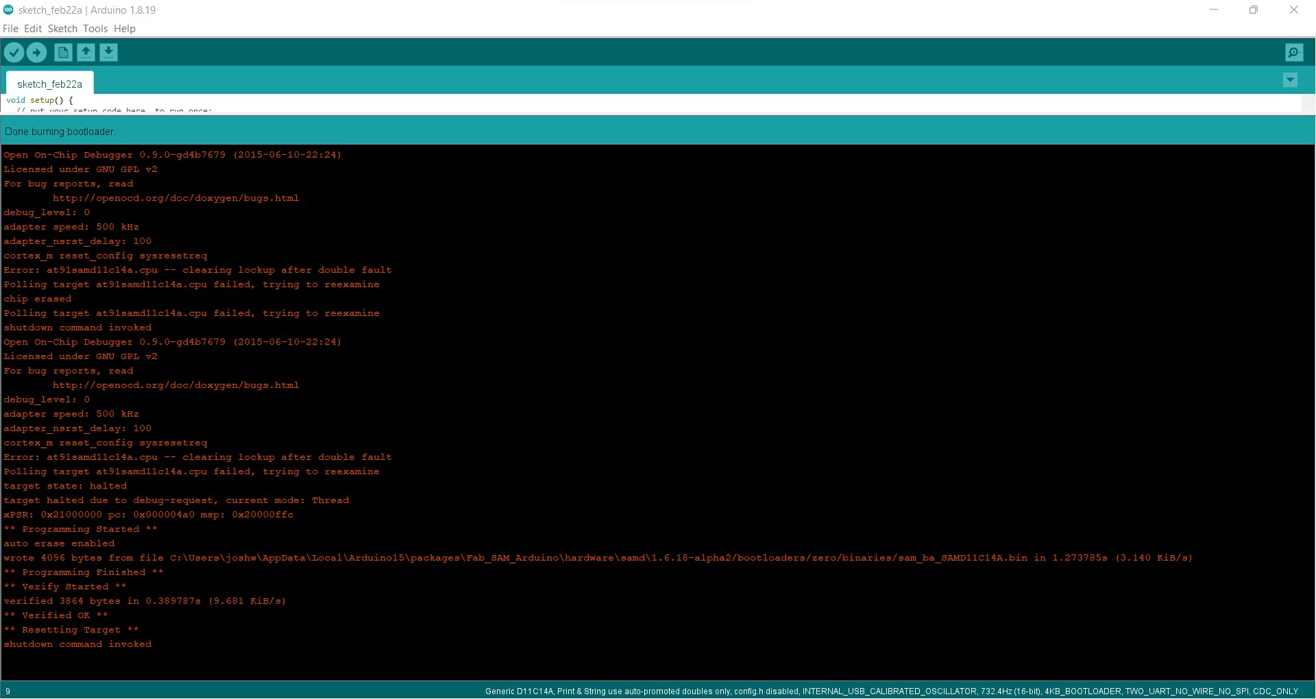
We may set aside the SWD programmer now that our programmer knows how to interact through a USB connection. Simply attach our UPDI Programmer to a USB port straight.
after cloning the SAMD11C serial repository from qbolsee’s repo open the SAMD11C_serial.ino from the cloned file and upload the program to the UPDI programmer *note change the port to a corresponding one from Tools
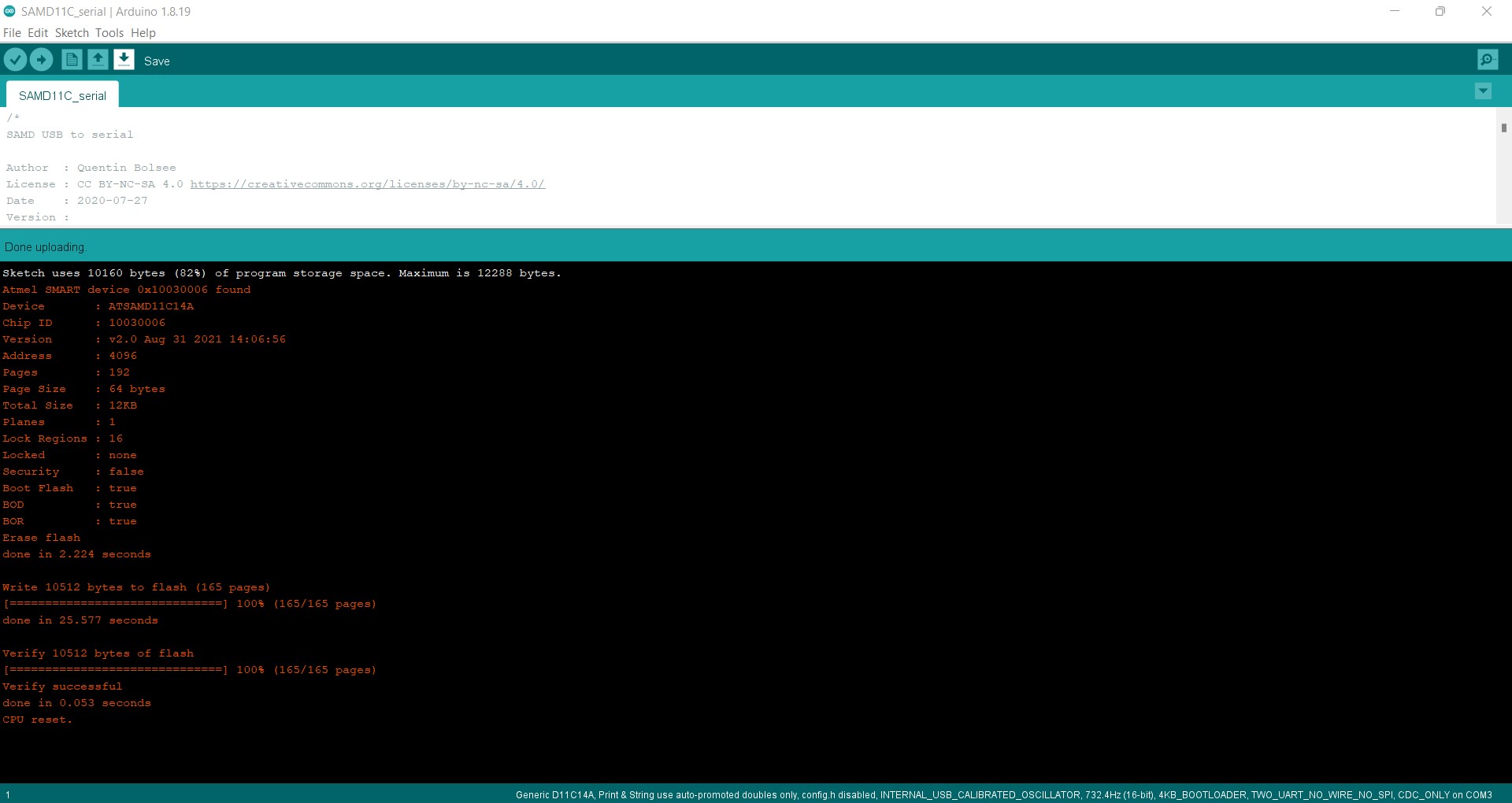
The board is now verified to be working after the program was successfully uploaded and the physical connections were tested and verified.