5. Electronics production
Week 4 - 2/16/22
This week, we created a PCB that we milled and stuffed. This circuit board will be used for programming other microcontrollers in the future.
I milled the PCB out with a micro-mill. I soldered components onto the pcb. I programmed the board with a bootloader. I programmed the board to act as a programmer. I created a simple attiny412 circuit to blink an LED and programmed it with my programmer.
Design
-
The board file was based off of this design: https://fabacademy.org/2020/labs/ulb/students/quentin-bolsee/projects/samd11c_uart-updi/
-
The above board was modified by Dr. Adam Harris and information about it can be found:https://sheekgeek.org/2022/adamsheekgeek/samd11c-multi-use-board
-
The files for the pcb can be found on Adam Harris’ GitLab page here: https://gitlab.fabcloud.org/acharris/fab11c
-
I followed the instructions also created by Dr. Adam Harris from his webpage here: https://sheekgeek.org/2022/adamsheekgeek/how-to-export-to-a-cnc-from-kicad-and-fab-mods
-
And this very good video on the process of going from Mod to the SRM 20 mill. https://www.youtube.com/watch?v=znp10a4vALY
This is a render of Adam Harris’ board design, I believe the render was done in kicad.

Preparing to Mill
The first thing we need to do after choosing which programming board to make, is to make a pcb for it. And instead of etching or ordering a board, we’re going to mill a board.
Equipment and Software
I used a Roland SRM 20 mini mill. It has a small footprint, a decent work area, and an 8000rpm spindle. This mill was setup with a ~1 inch spoil board, on which we used double sided tape to stick double sided 1.2mm FR1 pcb material (we could have used single sided pcb material, but I didn’t know where it was kept till after I milled the board).
We used two endmills, a 1/64” 2 flute square end mill for cutting traces and a 1/32” for cutting out the board from the rest of the PCB material.
Images of the tip of the 1/64” endmill, magnified through a digital microscope. It’s tiny, and difficult to tell if it’s worn/dull.

There is an approximately 1.5” spoil board used on the mill with double sided tape to hold the FR1 material. This material needs to be cleaned throughly in order to get the double sided tape to stick well.
The mill is hooked up to a PC for control. We used Roland’s VPanel software to jog, home, and to run the horrible abortion of g-code like numeric control code Roland chose to use. Did I tell you how bad “rml” is yet? It’s bad. G-code is bad enough, but at least it’s something of a standard.
Toolpaths (also referred to as “CAM”, Computer Aided Manufacturing) was created using the Mod’s software. http://mods.cba.mit.edu
Mods
Mods is a unique CAM package, in terms of user interface. It uses image detection and black and white PNG files to find the lines and mill the outline.
We will be creating two programs. One image will have the traces, the lines of copper that connect signals across the board. The second image is the actual outline of the board, and will be used to cut the board from the rest of the PCB FR1 material. These image files came from the Adam Harris gitlab based on a board from https://fabacademy.org/2020/labs/ulb/students/quentin-bolsee/projects/samd11c_uart-updi/
When you go to Mods, the screen is almost completely white. To create a new program, right click and this brings up the main menu.
Right click, go to “Program” -> “Open Server Program” -> Under SRM-20 “PCB Png.” The Mods window for creating the tool path for the mill will appear.
Now we select which file to cut, in this case, it is the traces of the copper, and we select the file with the traces. Click “Slect PNG File” and select the file you wish to cut. You should see the image come up.


Next, we want to se the origin for X, Y and Z to 0 (it defaults to 10mm. Great for Z, it’s a built in safety. why for X and Y? That will just cause pain and problems.)
But set your origins, this is where the machine will move too, from where you set it’s xy and z positions on the mill. There are two origins. Keep that in mind.


Then we have to create a way to actually save the file. It doesn’t automatically save the file for us.
We want to change the part where we save the file. This is connected to the “Roland SRM-20 Milling Machine” and and is section labelled as “Web Sockets.” There’s a small button there that says “delete.” Click it, it deletes that object.
We want to replace it with an object to save it to our harddrive.
Right click, choose “modules” -> “open server module” -> and scroll down to select “File -> save”
Click on the “outputs file” button under “Roland SRM-20 Milling Machine” and the “inputs file (object)” on the “save file” module. They will connect with a “wire.”


Next, we want to change the number of stepovers that the tool cuts on our part. Stepovers is the amount the material will remove beyond what the bare minimum is.
In Mods, this is labelled as “Offset Number” It defaults to 4. Change it to 6.
Then click calculate. An image of the toolpaths for your part should appear, and a file with the extension rml should download to your computer. This is the code to sent to the Roland Mill to cut the traces of your part.

In order to create the output for the board to be cut from the material (to be contoured), we will do the same sort of program as above. However, we’ve set most of this up.
We can select our new PNG file, click on “select png file” and select the contour outline file.
We want to make two changes.
First, on the “Set PCB defaults” module, click the button that says “mill outline (1/32)” This will set the program for cutting with a larger diameter tool, a 1/32” endmill. If you’re using a different sized end mill, you need to make the change in the “Mill Raster 2d” module.

Second, I recommend changing your “speeds and feeds,” that is: how fast is the tool spinning, and how fast is the tool moving through the material. In this case, we’re going to leave our speeds alone (at the max the roland goes, around 8500 rpm.) However, we want to change our feed rate at the “Roland SRM-20 Milling Machine” module. Where it says “speed” (yes, another misnomer and a mis-unit, feed rates are measured in mm/min, not mm/s). Change this to 3 mm/s. This will slow down the tool when cutting the part out, and most likely provide a better cut, better tool life, and less likely to rip our parts off the tape.
Click “calculate” again and it should save a new file with the contour of your part ready to go.
Notes on Mods
-
When using the Mods software, the part zero is the bottom left corner of the part.
-
Pay attention to the DPI of the PNG file when using the Mods PNG CAM software. Make sure the dimensions of the board are close to what you would expect the size of the board to be.
-
Sometimes the Mods software will stop responding (at least I was having this issue when using Google Chrome.) In these cases, you’ll have to reload and rebuild your Mods system.
-
Change your X, Y, and Z origins to 0mm.
-
Change the number of stepovers (Mods calls this “offset number.” The radial depth of cut is referred too as the “offset stepover.” This is given as a ratio to the tool diameter. Who the hell designed this?
-
Mods software uses non-traditional machining jargon. Will start referring to GIF’s as “jiffs” and memes as “me-me’s” in retaliation.
-
Slow down the feedrate for the contour pass. 4 mm/s with a duller 1/32” endmill at just 8000 rpm is a little agressive.
-
If you know your 1/32” is getting dull, take shallower depth cuts for the contour pass. 0.015” is just a tad better. (note: there’s a school of thought that says you should take larger, because you’ll be using parts of the endmill that have not dulled out. But I’d be careful in this case with such a small endmill.)
Image of the Mods software in use for creating the traces of the board.

Milling the board
The SRM 20 ready to Go.

Using the Roland SRM-20 Mill
The Roland SRM-20 is fairly simple to use, and fairly basic.
The trickest part is remembered to set your origin and your tool offsets.
When you’re preparing the mill, use the jog section of the Vpanel to move the tool spindle around. We want to get it close to where we want the part to start being cut. Carefully lower the Z (the tool spindle) axis down (make sure you’re not on “continue” movement, it’s easy to break a tool if you do.) When you’ve got it near where you want the cut to start (and remember, Mods starts cutting on the bottom left of the part.) click the “XY” button under “Set Origin Point” Also Note: There are two “origin” buttons. One (the one of the top right of Vpanel) sets the origin, the one in the center bottom, moves the spindle to the origin.

Load the 1/64” endmill in the collet. Be careful, they’re dainty little tools. Tighten down the set screw.
Then very carefully lower the tool towards the material to be cut. When you’re about 5 mm above the part, un-tighten the set screw, allow the tool to gently fall, and then un-loosen the set-screw. Then click the “Z” “Set Origin Point” button in Vpanel. Your X, Y, and Z origins are now set.
When you’re ready to cut, click the “Cut” button in Vpanel. The below window pops up.

Click “Add” to select the file you wish to cut (it will be the one that you saved from Mods. It will likely have the same filename as the image, with the rml extension added). Then click “Output.” IMPORTANT: As soon as “Output” is clicked, the machine will start the spindle and start cutting.
Once the traces have been cut, we want to cut the contour. Change the tool to a 1/32” endmill. Then click on the “To Origin” “X/Y” button in Vpanel. This will move the tool to the X/Y origin. Then again lower the Z till the tool is about 3 mm above the part. Un-tighten the tool, let it drop, un-loosen it, and re-set your Z origin.
Then go to “Cut” select the other file, and click “Output.” You should soon have a completed board. Make sure the tool cut deep enough, and gently pry the board off the spol board and tape.
Now comes the fun part.
Tips and Tricks when operating the mill:
-
The jogging movement is controlled by Vpanel, and the options for the amount when pushing the jog keys is “continue” (not continuous, continue.) “100x” (which moves 1mm, not 100 microns as one might expect.), 10x and 1x. Maybe because this has been set for inches, but odd considering it’s a Japanese company.
-
As always when creating your part to be machined, create a system to “cut air,” ie, the tool is kept above the part, to make sure everything appears correct before committing to the part.
-
Be careful with the “continuous” jogging in Z. It wants to crash into the stock. Slow it down.
-
Use the Roland Japanese double sided tape. Way better than the Scotch Brand double sided tape we also have in the soldering lab.
-
Got to keep that lid closed.
-
Make sure that in the Vpanel, in the settings panel, it is set to millimeters.
-
When touching off the tool and setting offsets, allow the tool to drop slightly from the tool collet. You may also want to put gentle pressure on the pcb material, to allow for a slightly lower tool offset.
-
Important – Do not put the tool too deep in the collet. If you do this, the SRM 20 has an odd behavior, where when it reaches its negative Z limit, it will reverse to its positive Z position, and continue to mill the part in air. The tool needs to be approximately, at least 10 mm below the collet. This was an annoying issue. I looked through the RML code, and it seemed fine, and I’m used to receiving errors from a machine tool, not just seemingly random behavior.
-
Make sure to set both your X/Y origins as well as your Z origin.
Operation 1: Cutting Traces
The following are the settings we used with Mods and the Roland SRM 20 to cut out the traces of the board.
This is the PNG for the board traces.

| Operation 1 | Cutting Traces |
|---|---|
| Tool 1 | 1/64” (0.0156”) 2 Flute Square End Mill |
| Feed Rate | 240 mm/min |
| Spindle Speed | around 8300. |
| Style | Climb milling. |
| Rapid speed | 1800 mm/min |
| Total Depth of Cut | 0.004” (0.1mm) |
| Depth of Cut | 0.004” (0.1mm) |
| Number of Step downs | 1 |
| Number of Stepovers | 8 |
| Stepover amount | 0.0078” |
| run time | 16 minutes. |
Operation 2: Board Cut from Material
PNG for the Board Cutout:

| Operation 2 | Cutting Board Contour |
|---|---|
| Tool 2 | 1/32” (0.0312”) 2 Flute Square End Mill |
| Feed Rate | 240 mm/min |
| Spindle Speed | around 8300. |
| Style | Climb milling. |
| Rapid speed | 1800 mm/min |
| Total Depth of Cut | 0.072” (1.83mm) |
| Depth of Cut | 0.024” (0.6mm) |
| Number of Step downs | 4 |
| Number of Stepovers | NA |
| Stepover amount | NA |
| run time | 2 minutes. |
Image of the finished milled board. The below board only used 6 stepovers, which left a large amount of extra copper between traces. Using 8 stepovers removes a lot of extra material.

After the board comes out of the mill, there is some “weeding” to be done to the copper traces, very much like what was done with the vinyl. As this board is using the copper traces to be plugged into the USB port, the copper traces around this area should be removed. This was done fairly easily by scraping them off with an xacto knife.
Oppsies
I ran into a multitude of small, but important issues:
- I accidently used an older version of the above board design. It only differed slightly, but the PNG file for the traces was offset from the cutout layout by about 1 to 2 mm, and was missing one resistor. Was able to fix.
- If you can’t get the Roland VPanel software to work, it could be because (at least on a multi-user computer) someone else is logged in and has the application open. It will only allow one connection per computer. So either get that person to log off, or just restart the computer and log them off the mean way.
- the Mod software used to CAM out this board had issues downloading the file. Refreshing the page finally worked. (I am going to try and using the Mod Community Edition next time. http://modsproject.org/)
- Had near mental breakdown, as just putting code in and pushing the big green button, while not being able to see any of the gcode/control code is antithetical to everything I’ve ever been taught about machining. Because also, I’m going to rely on some half-assed CAM system that’s completely online based and then just send it to a few thousand dollar machine and just hope it all works out. Just no.
- The 1/64” endmill was starting to get slightly dull. Still acceptable results, but fine tearing was noted.
- Mod does not handle REST machining. Wasted some copper finding this out.
- When doing cutout of pcb, Mods and Roland SRM 20 didn’t want to actually cut through the entire depth. Had to drop offsets manually by about 0.6mm. This was due to earlier mentioned weird “Z limit” behavior of the SRM 20.
Soldering the Board
All of that was of course just to create the PCB. The next thing is to populate the board with components.
BOM
The below are the components used to populate the board. The render at the very beginning of this document provided the placement of the components.
| Designator | Component |
|---|---|
| U1 | SAMD11C14 |
| IC1 | 3.3v LDO regulator |
| JP1 | 2x3 pin header |
| C1,C2 | 1uF |
| M1 | 6-pin SMD male horizontal header FTDI |
| PwrLED1, LED | Red LED |
| M6 | AYZ0102AGRLC switch (or 3-pin vertical header) |
| R1, R2 | 330 ohm |
| R3 | 4.99k |
| R4 | 1.2k |
| R5 | 0 ohm jumper |

Soldering Introduction
I have soldered SMD components before, and I’m fairly comfortable with my soldering ability; that said, I’m not a fan of soldering SMD, especially with a typical soldering iron. I believe that using a hot air station or a reflow oven is a much more efficient and easier process.
The soldering was tricky, but not too difficult. The first board was a board that was an older version, created in error. This version was essentially the exact same as the other two, but missing the 1k resistor. I cut the trace and then soldered a 1k resistor between these two traces.
Notes:
This board is fairly simple, and the despite the tiny soldering, there aren’t too many tricks.
SMD LED’s have a tiny green line on them, this is the cathode. Make sure it is connected to ground.
Make sure you place pin 1 of the IC (SAMD11) in the correct location. Pin 1 on the IC will have a tiny dot next to it. This may be difficult to see without magnification.
Soldering
I used a temp controlled Weller Soldering station with a medium round tip, and a fairly thick solder (I forgot to get the details on it.) The iron was set to a toasty 640 degrees F.

The Atmel SAMD11C processor used. It was difficult seeing the dot that signifies pen 1 without a magnifying instrument.

The next image you can see the process of soldering. In this case, I started with the Atmel chip, as that can be one of the more difficult elements, and I like to have clear space around it to help me solder more effectively.
Next, I move on to the smaller component near by, such as the LED’s and capacitors. Make sure you place the LED’s in the proper direction. The tiny green line on the LED is the cathode. This should connect to ground. In this case, the green line on top, faces towards the SAMD11C, and the one in the middle of the board faces the 6 serial connection pins on the bottom of the board.

Continuing the process; adding on resistors and the power regulator.

Here you can see the board under a digital magnifier system, after it has been completely soldered. It’s not the prettiest thing in the world. I use this to check for any shorts, cold solder joints, or any other errors/mistakes.
Adam Harris gave me a great tip, don’t just look at the board from the top, like in this view, but tilt the board and look at the solder joints from an angle. This will help with better understanding how well you did with the soldering.

In this case, I didn’t like the look of some of the pins on the atmel chip above and re-flowed them.

This was my completed second board, that was made from the correct file, and includes an extra resistor.
On my third attempt, I found an iron with a finer tip, and thinner solder. The thinner solder is more important (to me) than the finer tip, but it allows a more precise flow of the amount of solder to the components. This helps keep the board “cleaner” and less likely to create shorts.
After all the practice, and smaller diameter solder, my connections started looking much better.

At least when I plug the board in to a USB port, one LED receives power and lights up. Bonus points, it didn’t smoke, it didn’t start a fire, and it didn’t blow up the computer.

Programming the board
With the pcb created, and the components soldered on, this is still just a pile of useless bits. It still needs to be given software (firmware) to be able to actually do something useful. This is the process of programming the board.
Once again, I used Adam Harris’ information on programming an SAMD11 board found here: https://sheekgeek.org/2022/adamsheekgeek/samd11c-multi-use-board
Equipment and software
This process was done on a Windows computer.
We used an Atmel ICE programmer.
the edbg debugger software found here: https://taradov.com/bin/edbg/
and the Arduino bootloader code found here: https://github.com/mattairtech/ArduinoCore-samd/blob/master/bootloaders/zero/binaries/sam_ba_Generic_D11C14A_SAMD11C14A.bin
Programming
I downloaded the edbg debugger, and the Arduino SAMD11 bootloader code.
Then I hooked the boards up to an Atmel ICE programmer. Note that as I was setting this up, I had the interface plug in the wrong side. I discovered this just after the photo was taken and plugged it in correctly.

Pin 3 is ground. Pin 1 is VCC. Pin 2 is SWDIO, Pin 4 is SWCLK, Pin 10 is reset.
The Ateml Ice programmer was plugged into a usb port on the computer.
I opened a windows command prompt and typed the following:
edbg-windows-r29.exe -bpv -e -t samd11 -f sam_ba_Generic_D11C14A_SAMD11C14A.bin
Let’s pause and break this command apart. Instead of blindly typing it in and hoping for some results, let’s at least have some idea what we’re commanding the software to do.
-
“Edbg-windows-r29.exe” is the program (version 29)
-
“-bpv” tells it to use three different options. “b” is “verbose” mode, which gives you extra information about what is occurring. “p” is telling the programmer to program the chip, and “v” verifies that the chip has been programmed correctly.
-
“-e” is another option, it erases the chip before programming it.
-
“-t samd11” is telling it to program the chip type for the SAMD11 microcontrollers.
-
“-f sam_ba_Generic…” is simply the file to be programmed to the chip, in this case, the arduino bootloader we downloaded.
Unfortunately I received an error: Error: invalid response during transfer (count = 0/1, status = 7)

This error was different than the one that Adam had received and warned about (a “status = 0” error) in his writeup, linked above.
Googling the error, I found this website, with comments from the author of the software himself: https://www.eevblog.com/forum/microcontrollers/does-anyone-have-experience-debugging-cmsis-dap-firmware-itself/50/
And his explanation: “In your case “invalid response during transfer (count = 0/1, status = 7)” means that debugger attempted to perform a transfer, but status=7 means that the target did not respond, and the 3-bit ACK code was all 1s. … but it seems like the target is not connected properly or pins are not toggling correctly.”
(and as a side note, while not helpful in this case, I did come across this interesting page while googling for help. https://fabacademy.org/2021/labs/kannai/instruction/tips/fa2022_embed_env/) UPDATED: I’m thankful I came across this, becuase this is how I actually programmed the boards.
I tried unplugging and replugging. And tried again and agin. I tried jiggling and playing with the cables, double checking the connections are set correctly, etc.
I also tried this with 3 different boards that I had built. And after all three failed to be programmed, I checked each and every board under the microscope, and then re-flowed each and every one trying to make sure it wasn’t a bad connection or any type of short. Again, no luck.
While I’m not 100% confident in my soldering ability, I do feel that producing 3 of the same boards, all with the inability to be programmed is unlikely. I’m thinking the problem lies in either the setup of cables from the programmer or the computer (I’m plugging them in wrong). However, at the present time, I have no clue as to where the issue lies, and it very well could be a bad solder joint or a short on the board.

Well that sure was a waste of a lot of time and components.
UPDATED: I talked to Denny and Adam and discovered what the problem was. You have to provide power to the board. The Atmel ICE does not actually provide power to the board. I was under the impression that plugging the cable to the VCC connection would power the board, but nope. So, to program this, plug it into a USB port to get power, and then program through the Atmel ICE programmer. Sigh.
Program the boards with a Raspberry Pi 3b
While trying to find the source of the error of edbg, I came across this fablab website from last year: https://fabacademy.org/2021/labs/kannai/instruction/tips/fa2022_usbserial_pi3_openocd/ This website has a bunch of different programming attempts using multiple tools, and I found one for the raspberry pi 3 (apparently they had problems with the Raspberry Pi 4.)
So I found an older Raspberry Pi 3b, and I started following the (limited) instructions on their website here: https://fabacademy.org/2021/labs/kannai/instruction/tips/fa2022_usbserial_pi3_openocd/
Preparation
Notes: Don’t forget to change Speed of Raspi CPU (I overclock mine.)
sudo nano /boot/config.txt
Turn on the networked GPIO (using raspi-config)
sudo raspi-config
(select interface options, turn on remote GPIO)
Downloading OpenOCD on raspberry pi 3b
If this is an older version of raspi os, you may have issues with git SSL certs. See below.
sudo apt-get update
sudo apt-get install git autoconf libtool make pkg-config libusb-1.0-0 libusb-1.0-0-dev

cd ~
mkdir fablab
cd fablab

git clone git://git.code.sf.net/p/openocd/code openocd-code

cd openocd-code
when I tried ./bootstrap: I got:
Cloning into '/home/pi/fablab/openocd-code/src/jtag/drivers/libjaylink'...
fatal: unable to access 'https://gitlab.zapb.de/libjaylink/libjaylink.git/': server certificate verification failed. CAfile: /etc/ssl/certs/ca-certificates.crt CRLfile: none
It needed SSL certs to download other git files. So I tried to update this.
Update SSL Certs (or just turn this off)
Had to update certificiates: https://stackoverflow.com/questions/21181231/server-certificate-verification-failed-cafile-etc-ssl-certs-ca-certificates-c
sudo apt update ; sudo apt-get install apt-transport-https ca-certificates -y ; sudo update-ca-certificates

sudo apt-get install --reinstall ca-certificates

sudo mkdir /usr/local/share/ca-certificates/cacert.org

sudo wget -P /usr/local/share/ca-certificates/cacert.org http://www.cacert.org/certs/root.crt http://www.cacert.org/certs/class3.crt

sudo update-ca-certificates

git config --global http.sslCAinfo /etc/ssl/certs/ca-certificates.crt
And then said “fuck it.”
export GIT_SSL_NO_VERIFY=1
(I WILL CHANGE THE ABOVE BACK AFTER THIS IS INSTALLED! export GIT_SSL_NO_VERIFY=0)
Installing OpenOCD on raspberry pi 3b
Compiling and installing OpenOCD
./bootstrap

./configure --enable-sysfsgpio --enable-bcm2835gpio

make

sudo make install

cd /usr/local/share/openocd/scripts/interface

ls

cat nano raspberrypi2-native.cfg
NOTES: As default in raspberrypi2-native.cfg , SWD CLK is GPIO_11 SWD DIO is GPIO_25 SWD RST does not set
Then I downloaded this SAMD11 file
cd ~
cd fablab

git clone https://gitlab.cba.mit.edu/pub/hello-world/atsamd11.git

cd atsamd11/bootloader

nano openocd.cfg
COPY THE FOLLOWING into openocd.cfg
source [find interface/raspberrypi2-native.cfg]
transport select swd

set CHIPNAME at91samd11c14a
source [find target/at91samdXX.cfg]


# did not yet manage to make a working setup using srst
# reset_config srst_only
# reset_config  srst_nogate

adapter speed 200

adapter srst delay 100
adapter srst pulse_width 100

bcm2835gpio swd_nums 25 24
bcm2835gpio trst_num 7
bcm2835gpio srst_num 18

init
targets
#reset halt
reset init

at91samd bootloader 0
program sam_ba_Generic_D11C14A_SAMD11C14A.bin verify
at91samd bootloader 4096
reset
shutdown
NOTE: Program a programmer programmer
If you want to program this board to use the Arduino IDE and code, use the above. But if you wish to use this board to program other boards, using SWD/JTAG, then you’ll want to download this file http://academy.cba.mit.edu/classes/embedded_programming/SWD/free_dap_d11c_mini.bin and change the above line of “program sam_ba_Generic_D11C14A_SAMD11C14A.bin verify” too: “program free_dap_d11c_mini.bin verify”
Back to programming for the Arduino IDE
You can set SWD pins like bcm2835gpio_swd_nums 25 24 SWD CLK is GPIO_25 SWD DIO is GPIO_24
Reset pin can be set like bcm2835gpio_srst_num 18 SWD RST is GPIO_18
Downloading Arduino Bootloader
We’re renaming this file to .org, so that we can replace it.
mv sam_ba_Generic_D11C14A_SAMD11C14A.bin sam_ba_Generic_D11C14A_SAMD11C14A.bin.org

cd ../..
Downloading the new arduino bootloader file
git clone https://github.com/mattairtech/ArduinoCore-samd.git

ls

cd ArduinoCore-samd/bootloaders/zero/binaries/

ls | grep SAMD11C
You should see two files with SAMD11C in the name. we are looking for: sam_ba_Generic_D11C14A_SAMD11C14A.bin We are going to move the file over to our bootloader folder to replace the file we renamed earlier.
cp sam_ba_Generic_D11C14A_SAMD11C14A.bin ~/fablab/atsamd11/bootloader/sam_ba_Generic_D11C14A_SAMD11C14A.bin

ls ~/fablab/atsamd11/bootloader/
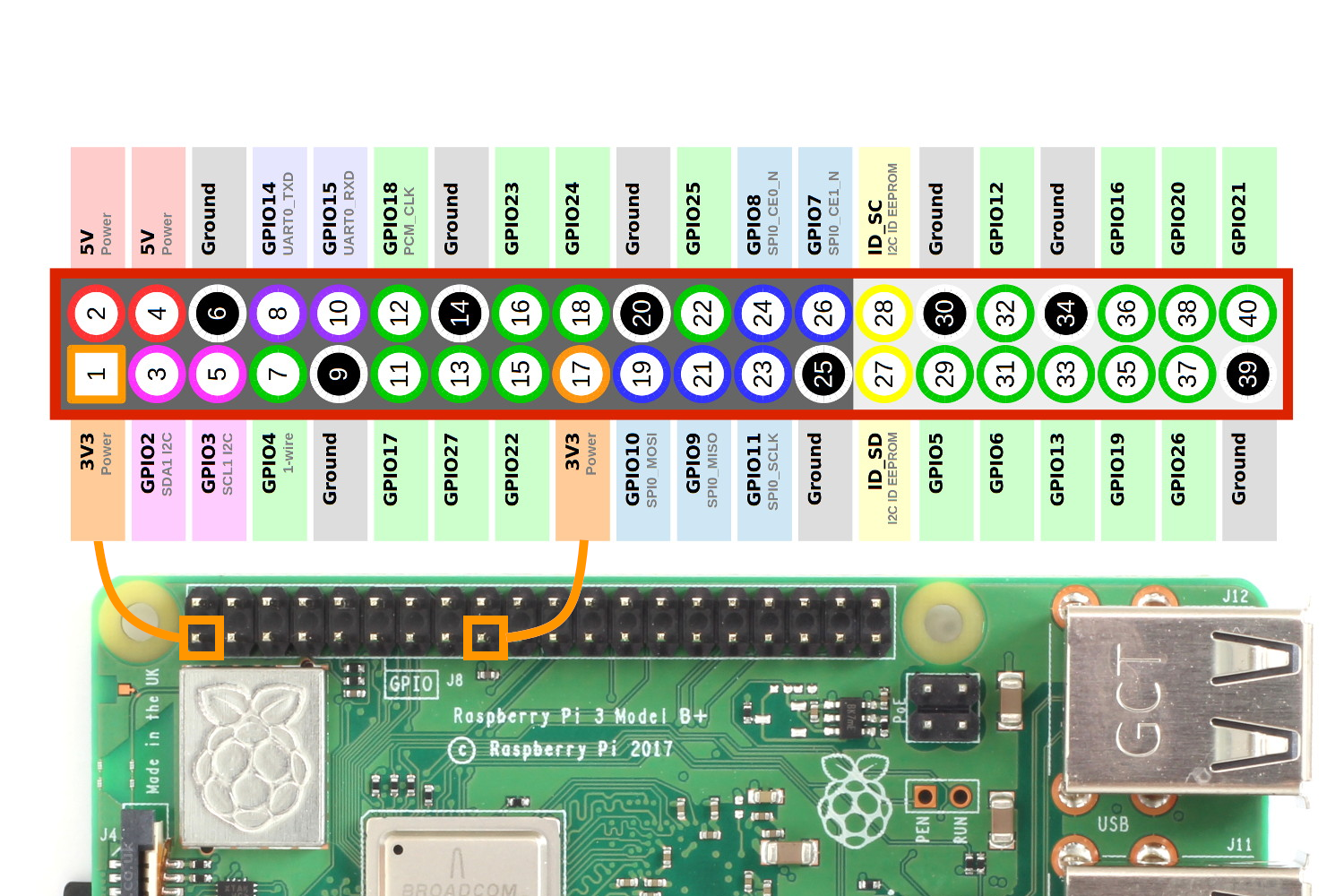
Connecting the Board to the Raspberry Pi 3b
Raspberry Pi GPIO Pin labels (I never knew this command existed, It’s very cool.)
pinout
And see here as well: https://www.raspberrypi-spy.co.uk/wp-content/uploads/2012/06/Raspberry-Pi-GPIO-Header-with-Photo.png
| SAMD11C Board | Raspberry Pi 3b |
|---|---|
| DIO (phys pin 8) | GPIO24 (pin 18) |
| CLK (phys pin 7) | GPIO25 (pin 22) |
| RST (phys pin 6) | GPIO18 (pin 12) |
| GND (pys pin 11) | GND (pin 20) |
| 3v3 (phys pin 12) | 3v3 power (pin 1) |
Note: You don’t actually have to connect power
Adam noted this when he forgot to hook up power and programmed it without it fine. This didn’t work for me with the Atmel ICE, but I’ve successfully programmed SAMD11C14’s with my raspberry pi by just hooking up DIO, CLK, RST, and GND. Weird, but it works.
Make sure if you’re using a dual power board, to set the switch to 3.3v.
When you connect these pins, you should see a the power LED light come on your board.

Programming....
And Then the actual programming
cd ~/fablab

cd atsamd11/bootloader

sudo openocd
pi@raspberrypi:~/fablab/atsamd11/bootloader $ sudo openocd
Open On-Chip Debugger 0.11.0+dev-00572-g94e7535be (2022-02-20-19:29)
Licensed under GNU GPL v2
For bug reports, read
        http://openocd.org/doc/doxygen/bugs.html
Info : BCM2835 GPIO JTAG/SWD bitbang driver
Info : clock speed 200 kHz
Info : SWD DPIDR 0x0bc11477
Info : at91samd11c14a.cpu: Cortex-M0+ r0p1 processor detected
Info : at91samd11c14a.cpu: target has 4 breakpoints, 2 watchpoints
Info : at91samd11c14a.cpu: external reset detected
Info : starting gdb server for at91samd11c14a.cpu on 3333
Info : Listening on port 3333 for gdb connections
target halted due to debug-request, current mode: Thread
xPSR: 0xd1000000 pc: 0xfffffffe msp: 0xfffffffc
target halted due to debug-request, current mode: Thread
xPSR: 0xd1000000 pc: 0xfffffffe msp: 0xfffffffc
** Programming Started **
Info : SAMD MCU: SAMD11C14A (16KB Flash, 4KB RAM)
Info : SWD DPIDR 0x0bc11477
Error: Failed to write memory at 0x00000558
Error: samd_write: 891
Error: error writing to flash at address 0x00000000 at offset 0x00000000
embedded:startup.tcl:1136: Error: ** Programming Failed **
in procedure 'script'
at file "embedded:startup.tcl", line 26
in procedure 'program' called at file "openocd.cfg", line 27
in procedure 'program_error' called at file "embedded:startup.tcl", line 1201
at file "embedded:startup.tcl", line 1136
Info : Listening on port 6666 for tcl connections
Info : Listening on port 4444 for telnet connections
Polling target at91samd11c14a.cpu failed, trying to reexamine
Info : SWD DPIDR 0x0bc11477
Info : at91samd11c14a.cpu: Cortex-M0+ r0p1 processor detected
Info : at91samd11c14a.cpu: target has 4 breakpoints, 2 watchpoints
Polling target at91samd11c14a.cpu failed, trying to reexamine
Info : SWD DPIDR 0x0bc11477
Info : at91samd11c14a.cpu: Cortex-M0+ r0p1 processor detected
Info : at91samd11c14a.cpu: target has 4 breakpoints, 2 watchpoints
I unplugged everything and ran it again. And supposedly it worked.
pi@raspberrypi:~/fablab/atsamd11/bootloader $ sudo openocd
Open On-Chip Debugger 0.11.0+dev-00572-g94e7535be (2022-02-20-19:29)
Licensed under GNU GPL v2
For bug reports, read
        http://openocd.org/doc/doxygen/bugs.html
Info : BCM2835 GPIO JTAG/SWD bitbang driver
Info : clock speed 200 kHz
Info : SWD DPIDR 0x0bc11477
Info : at91samd11c14a.cpu: Cortex-M0+ r0p1 processor detected
Info : at91samd11c14a.cpu: target has 4 breakpoints, 2 watchpoints
Info : at91samd11c14a.cpu: external reset detected
Info : starting gdb server for at91samd11c14a.cpu on 3333
Info : Listening on port 3333 for gdb connections
target halted due to debug-request, current mode: Thread
xPSR: 0xd1000000 pc: 0x000004a0 msp: 0x20000ffc
target halted due to debug-request, current mode: Thread
xPSR: 0xd1000000 pc: 0x000004a0 msp: 0x20000ffc
** Programming Started **
Info : SAMD MCU: SAMD11C14A (16KB Flash, 4KB RAM)
** Programming Finished **
** Verify Started **
** Verified OK **
shutdown command invoked
Info : Listening on port 6666 for tcl connections
Info : Listening on port 4444 for telnet connections
When I plug it in to the Raspberry Pi’s port, it sees something. That’s a start.
pi@raspberrypi:~/fablab/atsamd11/bootloader $ lsusb
Bus 001 Device 005: ID 16d0:0557 MCS
Programming with the Arduino IDE
And for the 10th time, this comes from Adam Harris’ website: https://sheekgeek.org/2022/adamsheekgeek/samd11c-multi-use-board
Setup
You may wish to make sure you have the latest version of the Arduino IDE installed. (I did not, and this caused a small hiccup installing the latest MattairTech SAMD board library for me.)
Then add the Mattairtech SAMD board library to the Board Manager section under File -> Preferences
https://www.mattairtech.com/software/arduino/package_MattairTech_index.json

and then go to Tools -> Board -> Board Manager.
Search for SAMD, and then in that window, click the install button for Mattairtech SAMD.

After doing this, make sure to check that your board is set up correctly!
Under the menu for Tools, go to Board and select “Generic D11C14A”
Make sure to choose the INTERNAL OSCILLATORS! Apparently if you choose an external crystal, your chip will be bricked.

Compiling and Uploading Code
Tested with Blink via Adam Harris (see below for the code). I copied and pasted this code into a new Arduino project.
I connected the board to my computer’s USB port, and made sure that it saw it on the COM port (check by looking under the Arduino IDE, Tools -> Port)
First I verified the code would compile by clicking the “Checkmark.” and the code compiled fine.
Then I uploaded the code to my board by clicking the “Upload” button. After a few minutes of compiling and uploading, the second LED began to blink.
//Adam Harris
//https://sheekgeek.org/2022/adamsheekgeek/samd11c-multi-use-board

int led = 2;

// the setup routine runs once when you press reset:
void setup() {
  // initialize the digital pin as an output.
  pinMode(led, OUTPUT);
}

void loop() {
  digitalWrite(led, HIGH);   // turn the LED on (HIGH is the voltage level)
  delay(1000);               // wait for a second
  digitalWrite(led, LOW);    // turn the LED off by making the voltage LOW
  delay(1000);               // wait for a second
}
And it blinked. Yay.
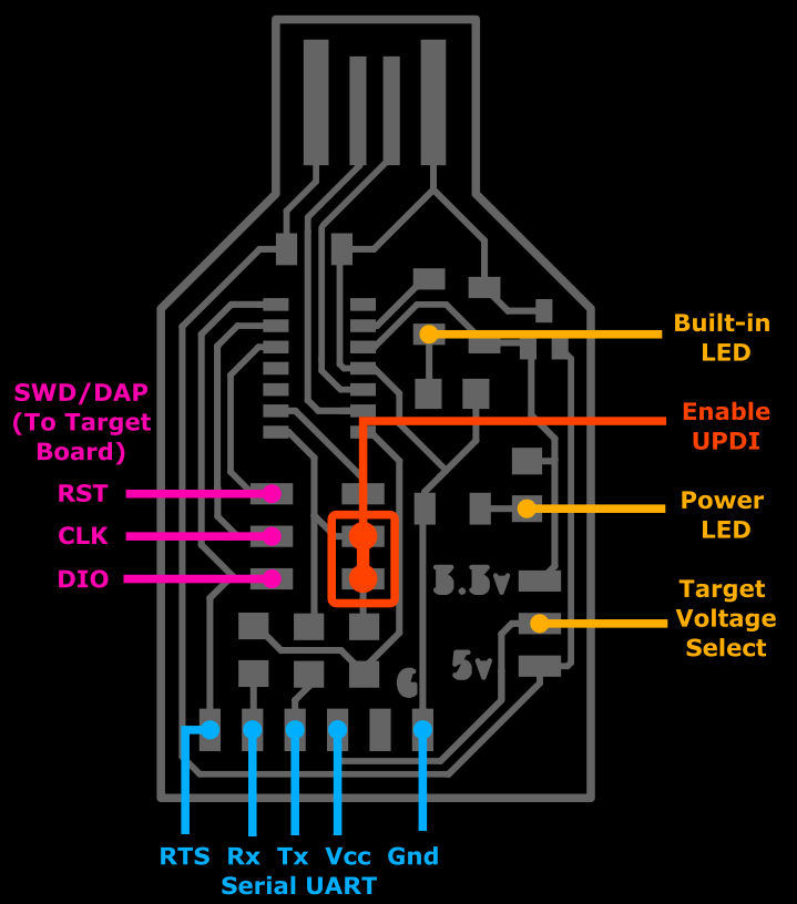
Programming a Programmer.
After this, I continued to follow Adam’s instructions and I installed his software on the programmmers to turn them into a UPDI programming board. I again used the Arduino IDE, and code supplied by Adam Harris.
// Adam Harris
// https://sheekgeek.org/2022/adamsheekgeek/samd11c-multi-use-board

void setup() {

   SerialUSB.begin(0);
   Serial1.begin(57600, SERIAL_8E2); //Adjust baud rate and use SERIAL_8N1 for regular serial port usage
}

void loop() {
   if (SerialUSB.available()) {
      Serial1.write((char) SerialUSB.read()); //Send stuff from Serial port to USB
   }
   if (Serial1.available()) {
      SerialUSB.write((char) Serial1.read()); //Send stuff from USB to serial port
   }
} //end loop
The pinouts of the programmer board are the following:
Got to make something to test with.
I had already made 3 of the same programming boards, all of which seemed to work, but I wanted to test with something else.
I milled and stuffed an attiny412 “blink” board, off of Neil’s design http://academy.cba.mit.edu/classes/embedded_programming/index.html (Look for Attiny412, it was the t412-blink-2)
Another issue with unsticky tape and an overaggresive, dull cutter cause this board to start moving during the cutout. I stopped the mill and just cut the board out with snips. Not pretty as it could be, but it’s just for testing purposes.

I then downloaded the arduino code that Neil had written and used the programmer to install it via the programming board.
In Arduino IDE, we need to set it up for working with the Attiny chips. This is the same as what we did before for the SAMD11.
In “File” -> “Preferences” click on the Additional Board Manager and add this to a new line:
http://drazzy.com/package_drazzy.com_index.json

Then click “Ok” and “Ok” again.
Then go to “Tools” -> “Boards” -> “Board Manager”
Then find the “megaTinyCore” library and install it.

When setting up the board via Arduino IDE, make sure to change the Chip selection to the Attiny412, and set the Programmer too: “Serial UDPI - SLOW, 56000 Baud”

Make sure that your programmer board is also setup correctly and everything is connected correctly. Make sure that you have a jumper installed in order to have it program UPDI. (image below shamelessly stolen from Adam Harris.)

Then upload the code to your board. Hopefully, you should see the attiny412 board start blinking.
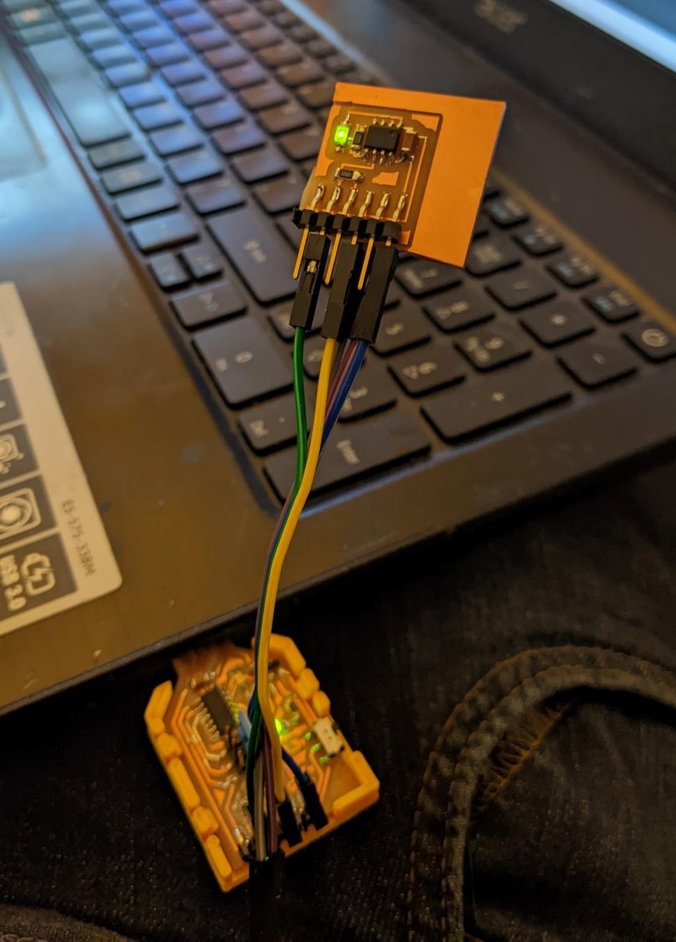
It Blinks.
Group Project
This week’s group project was all about testing the milling machine we used to make our pcbs.
You can find the group project for this week at the CPCC FabLab Site for Week 5.
I helped with the milling of the board and looking at the board to better measure it’s accuracy using the optical comparator. I also ordered the professional pcb’s.
Here’s one of the professional pcb’s all soldered up.

References;
References are listed through the website above.
For further information, I found this:
Possibly using a Raspberry Pi 4 for programming bootloader https://forums.raspberrypi.com/viewtopic.php?t=252551
Adafruit and OpenOCD: https://learn.adafruit.com/programming-microcontrollers-using-openocd-on-raspberry-pi
https://rawats.medium.com/using-raspberry-pi-for-embedded-systems-development-part-1-2d32c42acb5c
https://forum.kicad.info/t/errtype-3-pin-connected-to-some-others-pins-but-no-pin-to-drive-it/10946
https://ww1.microchip.com/downloads/en/DeviceDoc/ATtiny212-214-412-414-416-DataSheet-DS40002287A.pdf
page 559
https://www.youtube.com/watch?v=l9b_6WLemmg
http://sheekgeek.org/2020/adamsheekgeek/attiny412-general-purpose-blinky-board-and-updi-programming
https://fabacademy.org/2020/labs/oulu/students/achille-gakwaya/assignments/week07/
https://fabacademy.org/2020/labs/oulu/students/achille-gakwaya/assignments/week09/
https://fabacademy.org/2020/labs/oulu/students/noora-nyberg/assignments/week09/
https://www.reddit.com/r/AskElectronics/comments/8g21wf/what_is_the_difference_between_scl_and_sck/
http://www.bitbanging.space/posts/attiny-1-series-i2c-library
RML (Roland’s ‘g-code’) references
This is an ever-changing list of solutions to deal with roland’s rml.
-
Roland RML1 Programming manual: http://mlab.taik.fi/paja/wp-content/uploads/2011/01/RML1_Command_GuideENVer100.pdf