Week 8: Embedded Programming
Programming the Arduino or Fab HelloWold board is not a new topic since we already did the programming in earlier week. But this week is extensively focusing on how the coding works according with the controller we made or is already exist.
For that the important thing that we need to know is the Datasheet of the controller that we are going to do programming. Knowing the datasheet not only help us programming but also help to choose the right IC for our project. It is very important not to take this week for granted.
Instruction:
Read the data sheet for your microcontroller
Use your programmer to program your board to do something
Extra Credit:
☞ Try other programming languages and development environments
Group Assignment:
Compare the performance and development workflows for other architectures
- To Do:
- Learn and document on Programming the IC.
- Read the datasheet for the microcontroller.
- Learn different types of programming language to program the controllers.
- Program the board I have made to do something.
- Group Assignment.
Microcontroller
Microprocessor:
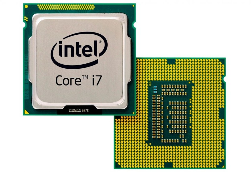
- A microprocessor is a Integrated Circuit that contains the arithmetic, logic, and control circuitry required to perform the functions of a computer's central processing unit. It's the stand alone IC which needs the peripherial circuits for it memories like RAM and ROMs.
- Usually circuits associated with microprocessors are complex because of the number of external peripherals attached.
- Microprocessors mainly contain only processing unit, peripherals like RAM, ROM etc. has to be connected externally.
- Battery consumption are high due to many peripheral circuits.
- Microprocessor is commonly used in general purpose applications like in a computer systems.
Microcontroller
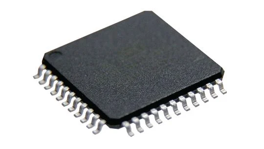
- It is an electronic Integrated Circuit (IC) which contains processing unit along with the other required peripheral components with fixed sized RAM and ROM.
- Usually circuits associated with microcontrollers are simple because most of the peripherals are embedded into the chip.
- Unlike microprocessors, microcontrollers have peripherals like RAM, ROM etc. embedded into the chip.
- Power consumption are lesscompare to processor.
- Microcontroller is commonly used for application specific purposes like in embedded systems. Since this week we are dealing with microcontroller rather than Microprocessor, lets focused on microcontroller.
Architecture
Architecture for the Integrated Circuits are mainly a set of rules or methods for functionality and organization of the system. It includes instruction set, design structure, logic and implementation.
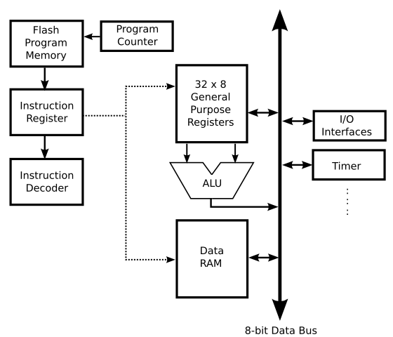
There are major two classification of architecture for controller and processor, that are Von Neumann and Havard architecture
| Von Neumann | Havard |
|---|---|
| It is ancient computer architecture based on stored program computer concept. | It is modern computer architecture based on Harvard Mark I relay based model. |
| It is cheaper in cost. | It is costly than Von Neumann Architecture. |
| Usually associated with Micro Processor and used in computers | It is used in micro controllers and signal processing. |
Datasheet Reading:
It is very important to understand the datasheet of the microcontroller that you are going to use or inorder to choose most suited for your project. Datasheet gives us clear idea about the microcontroller, it's structure and functionality.
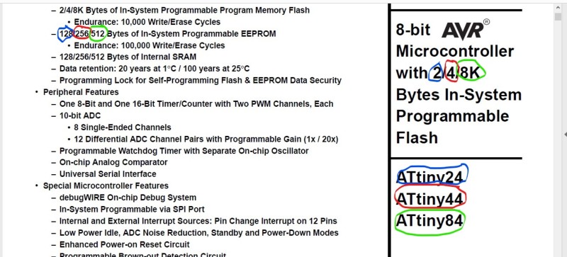
For Attiny24/44/84 are having the datasheet together since most of the features are almost same. So, it becomes bit tricky while reading the datasheet.
As I denoted in the above image with the color circle, the bytes of 2, 4 and 8K belongs to Attiny24, Attiny44 and Attiny84 respectively. Similarly, in the later datasheet which is given as 128/256/512 Bytes can be read as 128bytes for ATtiny24, 256Bytes for ATtiny44 and 512Bytes for ATtiny84.
Other than given in the XX/XX/XX, the features are common for all three types of ATtiny.
Important Features for ATtiny44 from Datasheet:
- 4K Bytes of In-System Programmable Program Memory Flash.
- 256 Bytes of In-System Programmable EEPROM.
- 256 Bytes of Internal SRAM.
Operating Voltage:
- 1.8 – 5.5V for ATtiny44V
- 2.7 – 5.5V for ATtiny44
Power Consumption:
- Active Mode (1 MHz System Clock): 300 μA @ 1.8V
- Power-Down Mode: 0.1 μA @ 1.8V
Pin Configuration:
Important thing from datasheet reading is the pin configuration of our ATtiny. It is very important to understand the pin configuration in order for the connection and programming of the IC.
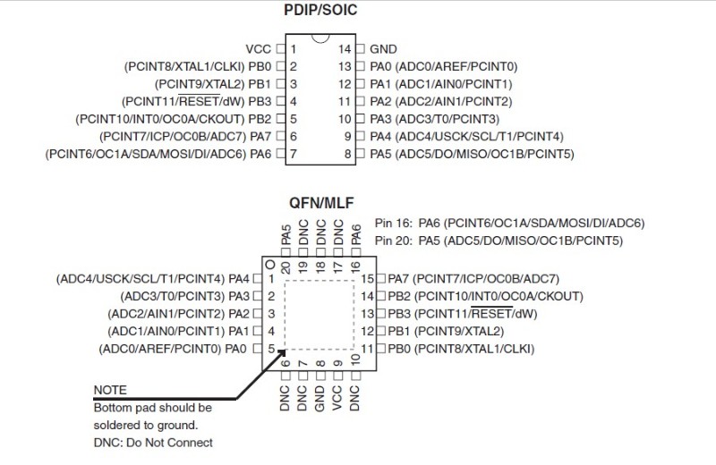
This pin configuration will help us understand the IC connection and pin responsibilities. Though this helps us understand the pin addresses, we cannot us pin address from above image to program using arduino IDE. Different IDE have different pin address for programming.
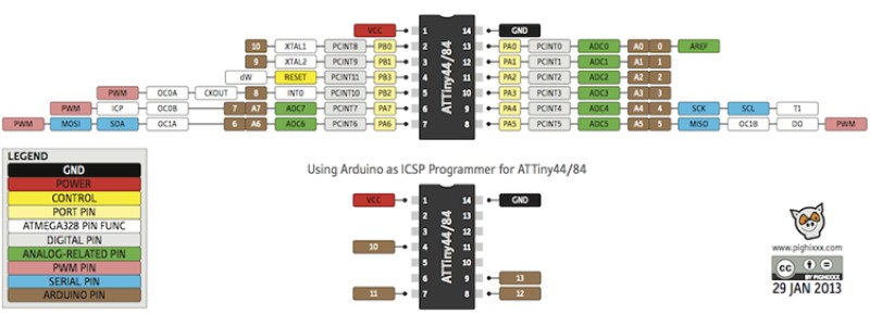
Programming
Programming with arduino
First I tried the programming with the Arduino IDE with the simple blinking code and Button controlled LED code.
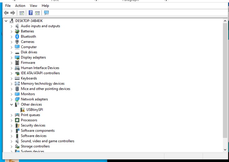
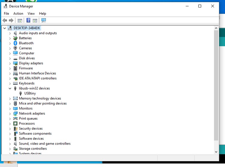
Unfortunately when I insert my usbtiny to my pc usb port, it is unable to read my usbtiny and couldn't load the program. Later I checked in the Device manager and found that it requires the driver.
About the installation of USBtiny driver and programming of ATtiny using Arduino Ide, it is well documented in the link here
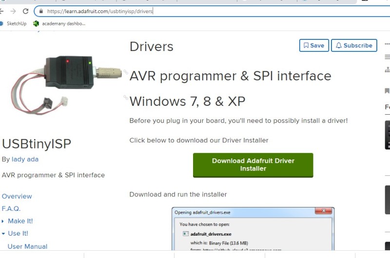
From the link given above, downloaded the driver for USBtiny and it worked. USBtiny became readable in the Device manager.
Now in the arduino Ide, we need to setup the board and ports for programming.
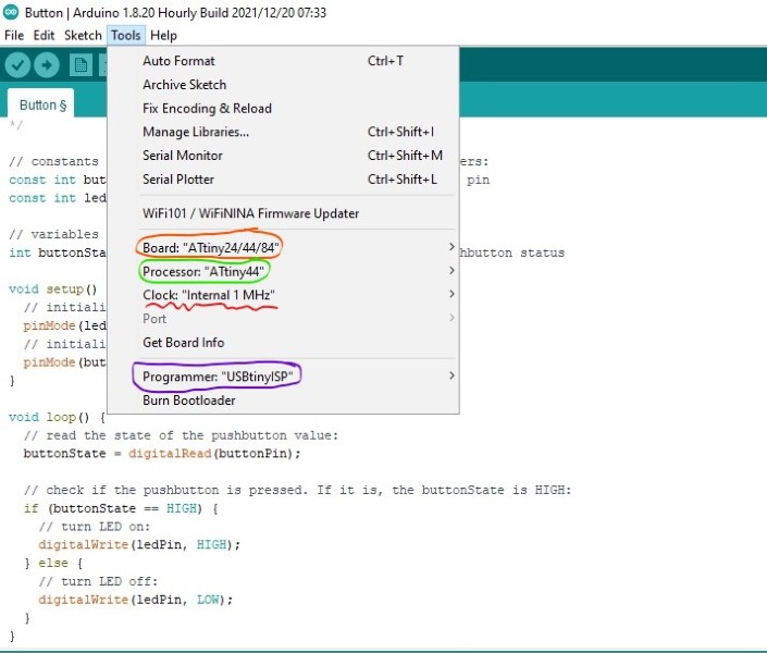
Choose ATtiny24/44/84 for the Boards, ATtiny44 as th Processor and USBtinyISP as the programmer. Clock I have selected 20MHz external, but the frequency of blink is varying too much but working okay with internal 1MHz.
My code as below:
	const int buttonPin = 7;     // the number of the pushbutton pin
	const int ledPin =  8;      // the number of the LED pin

	// variables will change:
	int buttonState = 0;         // variable for reading the pushbutton status

	void setup() {
	  // initialize the LED pin as an output:
	  pinMode(ledPin, OUTPUT);
	  // initialize the pushbutton pin as an input:
	  pinMode(buttonPin, INPUT);
	}

	void loop() {
	  // read the state of the pushbutton value:
	  buttonState = digitalRead(buttonPin);

	  // when button is pressed, LED will blink twice
	  if (buttonState == HIGH) {
	    // turn LED on:
	    digitalWrite(ledPin, HIGH);
	    delay(1000);
	    digitalWrite(ledPin, LOW);
	    delay(1000);
	    digitalWrite(ledPin, HIGH);
	    delay(1000);
	    digitalWrite(ledPin, LOW);
	    delay(1000);
	    digitalWrite(ledPin, HIGH);
	    delay(1000);
	    digitalWrite(ledPin, LOW);
	    delay(1000);
	    digitalWrite(ledPin, HIGH);
	    delay(1000);
	    digitalWrite(ledPin, LOW);
	  } else {
	    // turn LED off:
	    digitalWrite(ledPin, LOW);
	  }
	}
After the program is loaded, it worked and the video is as below.
Reference
- Microcontroller and microprocessor: https://eeeproject.com/microprocessor-vs-microcontroller/
- Microcontroller Architecture: https://ccrma.stanford.edu/wiki/Microcontroller_Architecture
- ATtiny Datasheet: https://www.alldatasheet.com/view_datasheet.jsp?Searchword=ATTINY44&sField=4
- Attiny44 with Arduino: https://42bots.com/tutorials/programming-attiny84-attiny44-with-arduino-uno/