Week 7: Computer-Controlled Machining
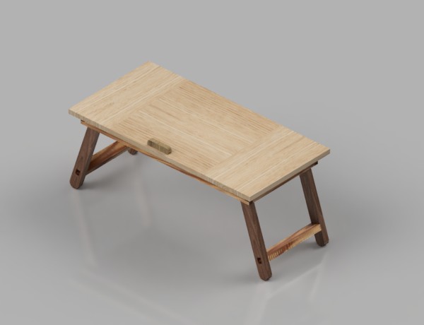
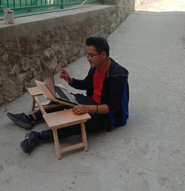
A very exciting week as we are going to make something big in CNC machine. Amid the covid situation, where the lockdown is frequent and most of the work should be done from home, I really feel discomfort. Sitting in the bed, working on the laptop and designing is really a challenge. I feel the real need of laptop desk which is adjustable.
So, this week I'm working on myself.
Instruction:
Make (design+mill+assemble) something big (~meter-scale)
Extra Credit:
☞ Don't use fasteners or glue
Extra Credit:
☞ Include curved surfaces
Group Assignment:
Do your lab's safety training
test runout, alignment, fixturing, speeds, feeds, materials, and toolpaths for your machine
- To Do:
- Design a adjustable laptop table.
- Learn on how to operate CNC machine.
- Cut parts and finding the faults.
- Assembling and documenting.
- Group Assignment.
Computerized-Numerical-Controlled Machine
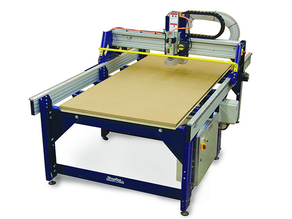
The one that we have in Fablab Mandala is the 3 axis Shopbot. It is the machine with three or more gantries, controlled numerically by computer. It's functionings are similar to that of Milling machine but CNC routers are used for heavy works.
A CNC (Computer numerical Control) is basically a machine that performs a process based on data from a computer. The CNC is a 3-Dimensional machine that moves based on the coordinated and measurement data provided from a design file.
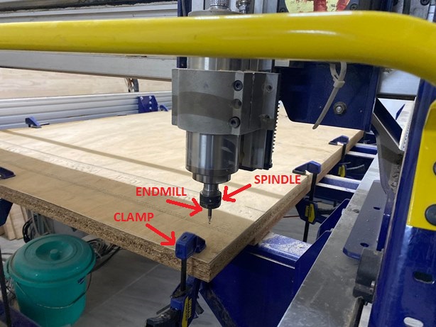
Some important parts we need to know when working with CNC router are:
Spindle
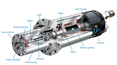
It is the important rotary part of the machine. CNC spindle often refers to the shaft at the center of the rotating axis of the machine tools, sometimes spindle is used to refer to the entire rotary unit, including not only the shaft itself but its bearings and anything attached to it.
Collet
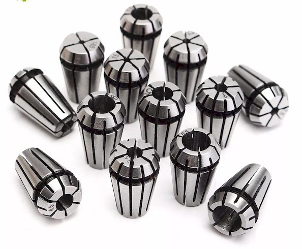
Collets are a type of chuck and are an essential part of Workholding. A collet works in conjunction with a spindle and is one of the core components in CNC turning and CNC lathes. Collet chucks allow for a consistent gripping force when machining. From google
End Mills
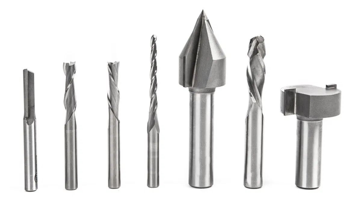
CNC machines use end mills that cut laterally (side to side). End mills have cutting surfaces called flutes. The most common end mills have two to four flutes. Generally, fewer flutes evacuate more chips from your material, keeping the bit cool. However, more flutes produce a finer edge finish. From google
Designing Table:
We can do designing in either 2D design software or 3D designing software. After having the clear idea on what to design for CNC, it is very easy to design using 2D software but it's limitation doesn't let us see the design fault and checking.
3D desinging software are completed compared to 2D software but are more dynamic and can check on how our output will be in real after fabricating.
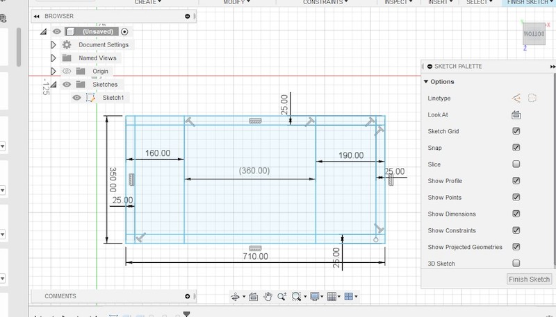
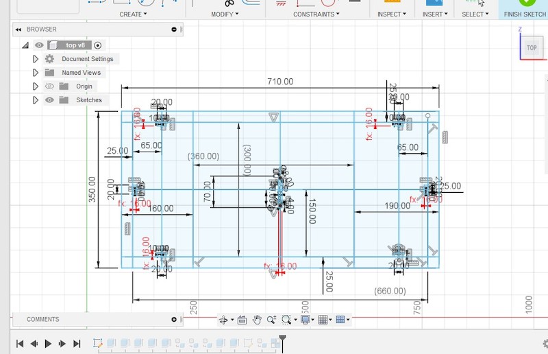
I started th design from the top of the table. My table top is divided into three parts, left small part for hand resting, right medium part for mouse and mid major part for holding the laptop. The middle section of the table will be movable to adjust angle.
- Designing parameters
- Thickness: 8mm (Changeable according to materials we get)
- Mid laptop holding part: 360mm (My laptop measures only around 340mm, so good enough at 360mm)
- Right mouse pad part: 190mm (it's good enough with estimation)
- Left hand rest or other purpose part: 160mm (free design as per required)
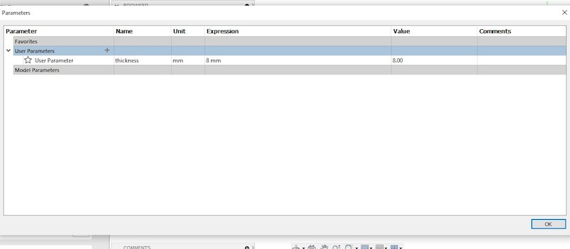
The most important thing that we need to check in this designing is the thickness of the plank/materials. Usually we do not get the required thickness of material here and we need to adjust with what we get. Therefore, I kept the thickness as parametric which i can easily change later with the materials thickness I get.
But when later I realise that thickness of only 8mm is very thin and wanted to change the parameter to 16mm. To my awe, above errors where shown instead of changing all the required parameters to 16mm. I had to delete all the nearby parameters and set again using 16mm thickness.
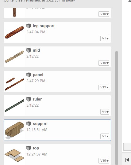
I designed every parts individually, so that later I can assemble and trace out the errors.
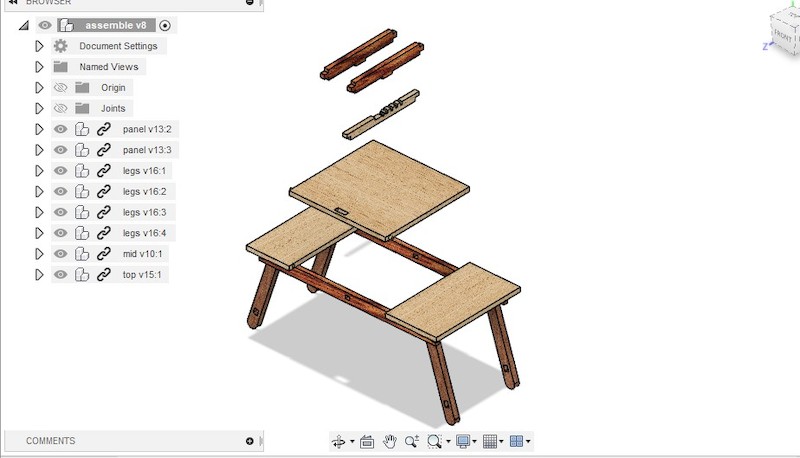
After the completion of designing all the required parts, I started assembling in order to check the design and errors. Few errors like overlooking of thickness and sizes came out but there wasn't any major issue in the design.
In this design, with the rod length of 115mm, I checked the possible angle that my table can stand.
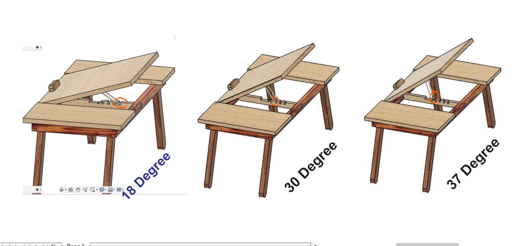
This are few satifactory angle I can get.
I tried rendering in fusion
Original file Here.
Setup file and Cutting
In order for our design to cut in the Machine, we need to create the toolpath which is known as cam toolpath. Only with the CAM toolpath the machine will understands in which way it should cut.
Creating of CAM tool and cutting in CNC takes two softwares Aspire and ShopBot 3.
First we created the Tool paths in Aspire and than using ShopBot 3 we feed our design.
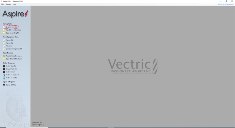
First we need to open Aspire software and create a new file using Create a new file option as shown above.
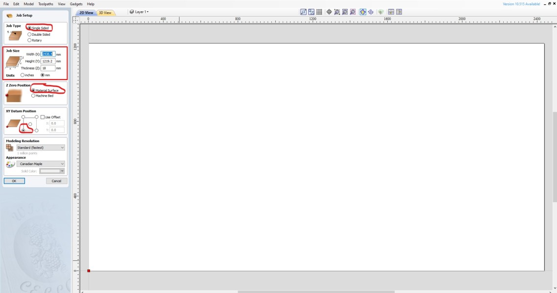
Create new file option takes us to File Setup page where we need to setup parameters of our material to be used for cutting in machine.
- Job Type - select Single Sided as we are going to cut from one side only.
- Job Size we need to setup as per our materials. Width(X) and Height(Y) are the parameters of the material that we are going to use. Usually Ply that we get are of 8 feet by 4 feet which is equivalent to 2438.4mm by 1219.2mm. Thickness, Set to the thickness of the materials that we have.
- Z zero Position should be on the Material Surface as zero setting will be on the material.
- XY Datum Position should be on front left side as shown in image.
After the setup, we need to click on Okay.
- Material details for my table
- Length: 2438.4mm
- Width: 1219.2mm
- Thickness: 8mm
- Material: wood board
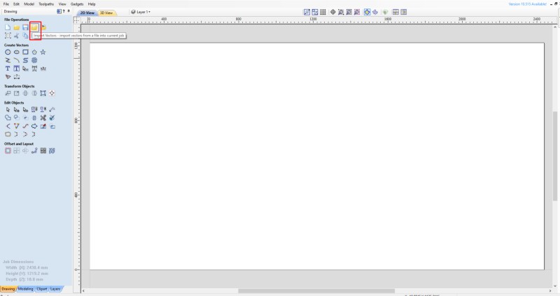
Okay button takes us to the above page where we can import file and create the tool paths. Using the Import Vector to import the files.
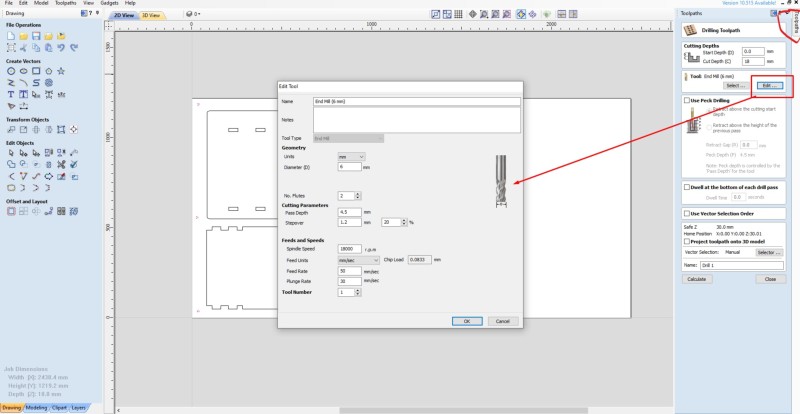
- We need to edit the tools setting if required but not from the Select but from Edit
- End mill diameter: 6mm
- Number of Flutes: 2
- Pass Depth: 3.5mm
- Step Over: 1.2mm
- Feed Rate: 50mm/min
- Plunge Rate: 30mm/min
- Spindle Speed: 1800RPM
Once the files are set, it's time to set the the toolpath. Go to ToolPath on the right top side to set the tool path. Cut Depth is the usually the thickness of the materials but it is always wise to keep few mm extra.
The most important thing we need to setup will be Tool: End Mill (X mm) which will let us select end mill, cutting parameters, Feeds and speeds.
Pass Depth in Cutting Parameter usually need to be half of the diameter of the endmill but it's good to have 2/3rd of the diameter.
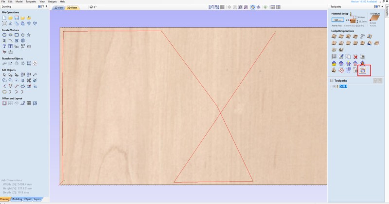
Once done with the set up of toolpath, we can do calculate which is at the end of the setup page. It will let us see the preview of the job, close the preview page and it's time to save the toolpath file.
Save icon is marked in above image. Once Saved, we are ready to cut in machine.
Cutting & Fixing
After setting the toolpath and saved, now we can go with cutting in the machine. ShopBot 3 is the machine application, using ShopBot 3 we can control and make machine run.
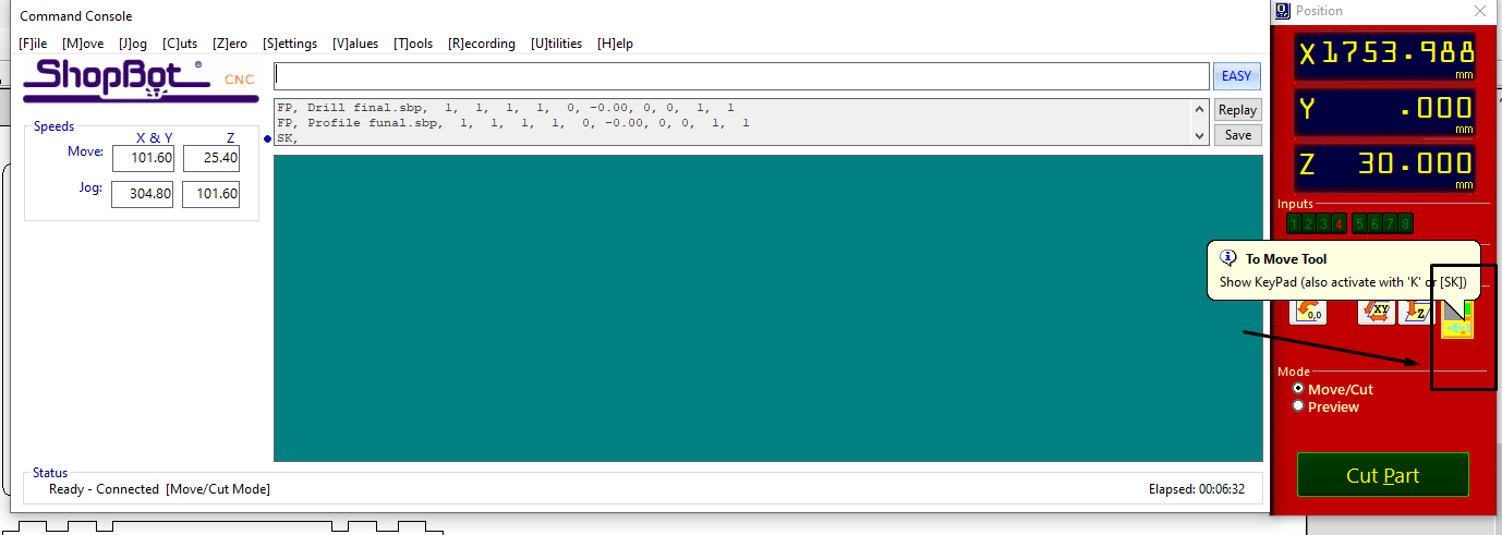
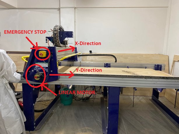
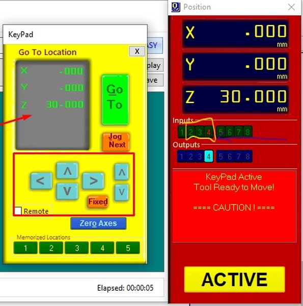
Opening the ShopBot 3 will let us to the application home page. Now open KeyPad using highlight icon as shown above image. With KeyPad controller, we can control the machine's coordinate of X, Y and Z.
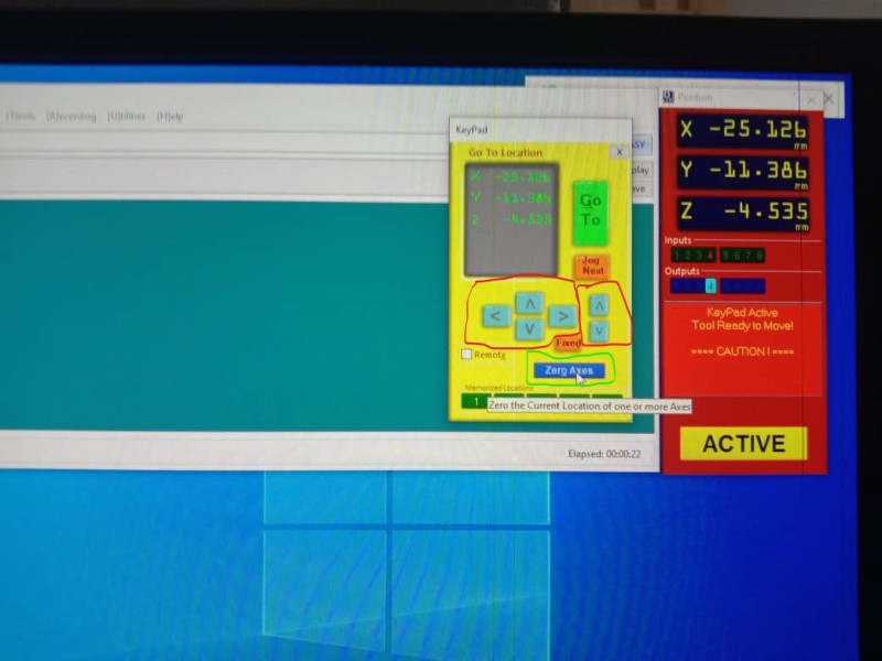
Move X,Y and Z coordinate using < ^ v > tabs. When X,Y and Z gets to your desired position, Make position as Zeroes using Zero Axes tab.
*It is a good practice to always pick a Z axis little bit up after setting to zero because it will avoid breaking of endmill in accidental movement of X and Y axes, though Z axis will automatically move up when running.
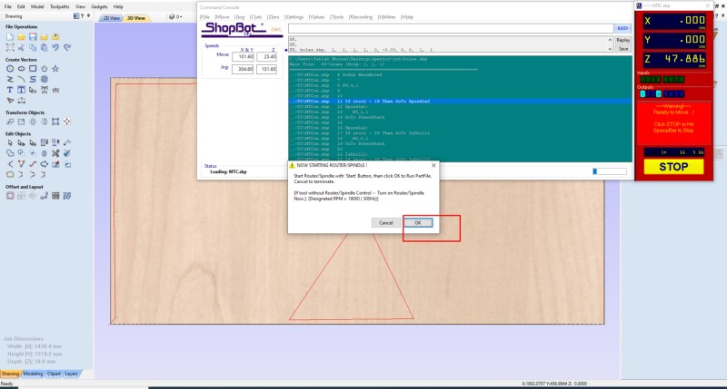
Now closing of KeyPad will change the Active tab to Cut tab in the Position window. Select the file to be cut using Cut tab make it Start.
Though ShopBot CNC have auto start of spindle after making it Start, CNC in our lab have been modified as real spindle of Shopbot got demaged, so we need to start spindle manually and wait until it get to full speed and select Okay button of shown above to start working.
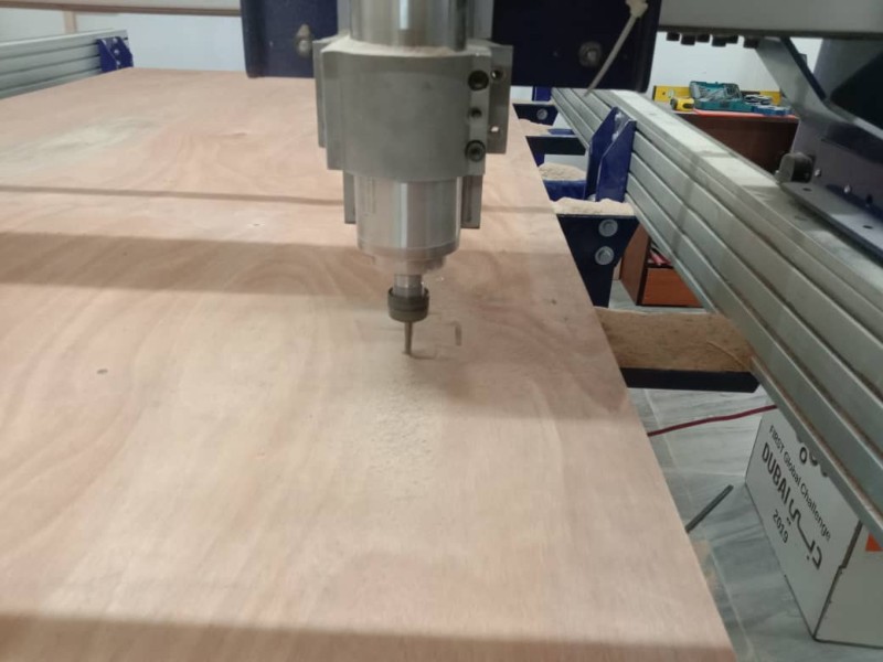
First we did the test cut to see if it fully cut through or not with single design and it came out pretty well. Knowing that setting of machine and it's axes are good, I proceeded with other parts cutting.
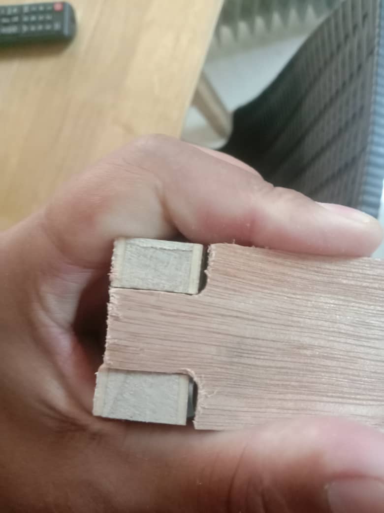
After the cutting I tried to check my joint parts of how good it is and found that due to CNC bit creating curve instead of clean corner cut, it wasn't going in well as shown above. So, I have to file the edges and corner to make it fit well.
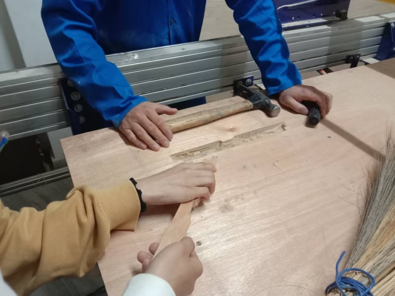
Due to low quality board we used to make our product, I had to use wood glue to properly join my table joints.
The end product came out to be very satisfying and impressive. I liked my product and also got love from my colleagues. It came to be comfortable for me working from home now.
Problems and Errors:
Since it is to make something big, bigger than just prototype, many errors and problems were expected. But luckily due to Fusion 360 feature of assembling the parts before manufacturing reduces many expected errors of the design.
Yet I forgot consider the way machine drill works and I had to do sanding the edges and corners of the joints. This is not the design error or major problem, but caused due to the nature of the machine works.
Such problem usually we can over come by designing dog born joints rather than simple straight joints like mine.
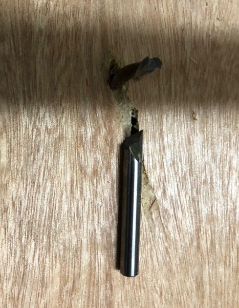
This became my major mistake when I broke the end mill. Due to some unknown problem, machine got struck in between the job with Highlight of input pin 2 3 & 4 of position window.
I restarted the computer connected to the machine and highlight removed. So I tried to move the machine to it's zero position without knowing that the axes value changed due to restart of machine. So, endmill got struck in the ply and was broken.
Assignment Files:
3D file Here.