Task to be carried out this week
Action Plan
| Date | Work Allocation |
| 9th March | Prof. Neil's Lecture on Computer Controlled Cutting |
| 10th March | Learning about CNC machines and safty rules(Group Assignment) |
| 11th March | Design using Fusion360 |
| 12th March | Design using Fusion360 |
| 13th March | Cutting the design using CNC machine (At halt due to lockdown) |
| 14th March | Assembly of design cutouts |
| 15th March | Documentation |
Introduction to CNC Machining
What is CNC?
CNC stands for Computerized Numerical Control. It is a computerized manufacturing process in which pre-programmed software and code controls the movement of production equipment.
What are CNC Machines?
Computer Numerical Control machines are automated machines, which are operated by computers executing pre-programmed sequences of controlled commands. CNC machines are essentially the opposite of old-school
devices that are manually controlled by hand wheels or levers, or mechanically automated by cams alone. Modern CNC machines understand and function using CNC machining language called G-code which tells them
precise measurements for production, like feed rate, speed, location, and coordination.
Designing using Autodesk Fusion 360
For my individual assignment for the week, I had to make something bif using CNC machine. I was pondering about what to make and started surfing the internet for interesting ideas.
For my final project I needed a table on which I could mount my kiln on. So, I decided to make a table big enough to fit the kiln on. I started by looking up on the internet for interesting table designs.
Since we get extra credits if we don't use fasteners or glue, I looked for designs for table where by the joints could be made by press-fit joints. I decided on making a circular top table with to cross-joint legs that could be connected using press-fit joints.
I used fusion 360 to make my design.
For the first step, I defined the parameters so that it would be easier for me to scale my model if changes are required. To do that, I used the steps I followed during computer-controlled cutting week.
I defined the following parameters;
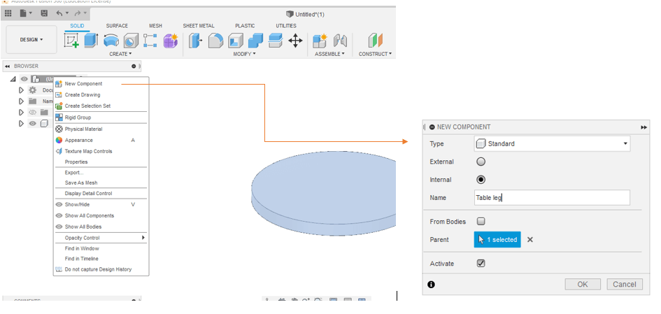
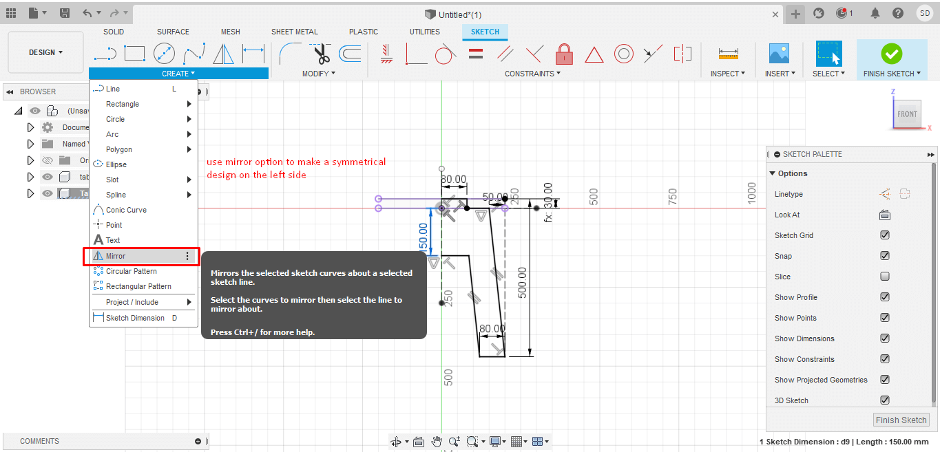
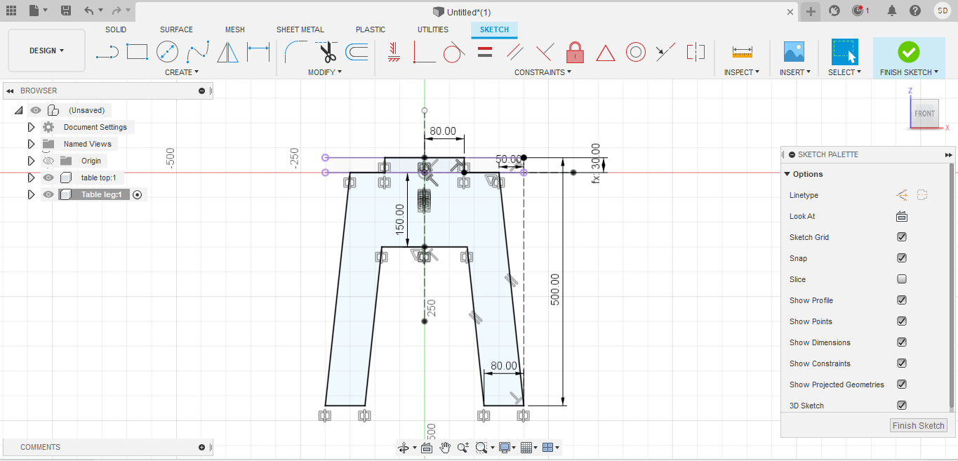
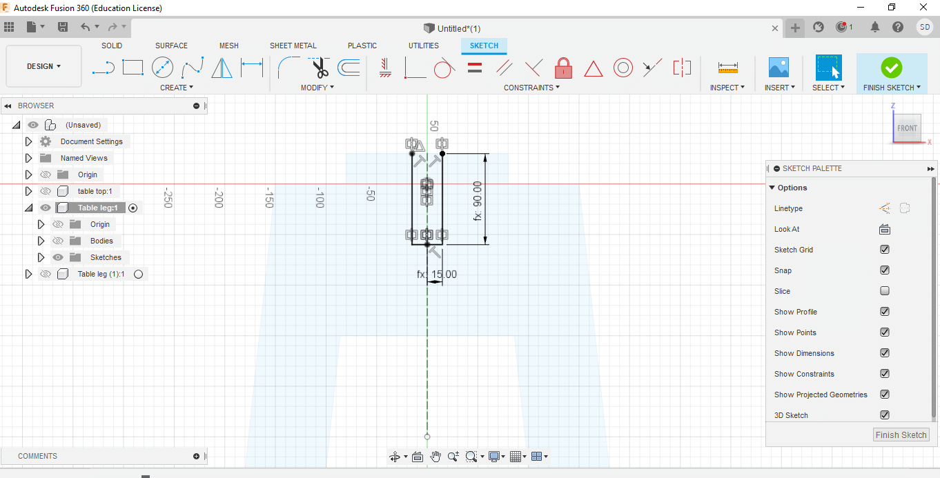
I began making a sketch for my table leg. I sketched only half of the table leg and then mirrored it to get a symmetrical leg.
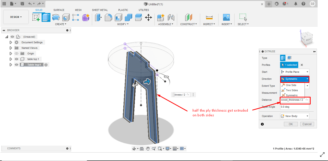
Next I extruded the leg to the pre-defined ply_thickness parameter. Since I wanted the leg-placement in the center, I used the symmetrical in direction box. I noticed that the sketch gets extruded on both side so the thickness becomes double the ply/ wood thickness I need. Thus, in for the thickness amount I gave "half of ply_thickness". Thus when the sketch gets extruded, the total thickness comes to the ply_thickness parameter defined.
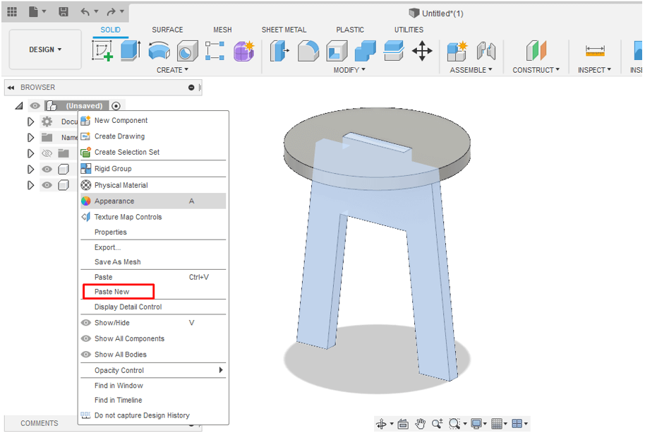
For creating the second leg, instead of sketching from base, I simply made a copy of the already created leg.
Right-click on the created leg component → Copy → right-click on project file → select paste new
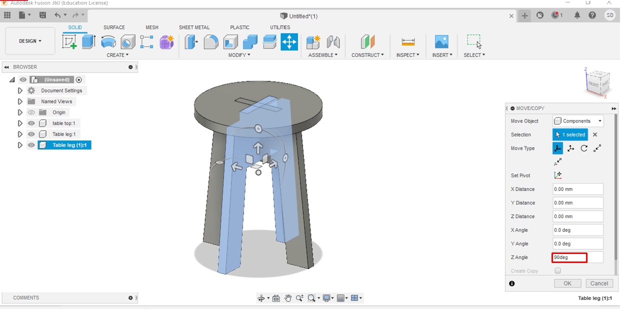
Now move and place the leg in the position I wanted. I rotated the leg by 90 degree on z angle to make the two legs perpendicular to eachother.
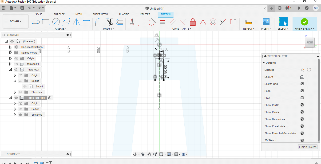
Next I had to create press-fit joints so that I can assemble the table without using any external jointers or glue. To do that, I created a sketch on the table legs and extruded with negative ply-thickness. For the leg1, I create the joint on top and for the second leg, I created it at the bottom as shown in the figue below.
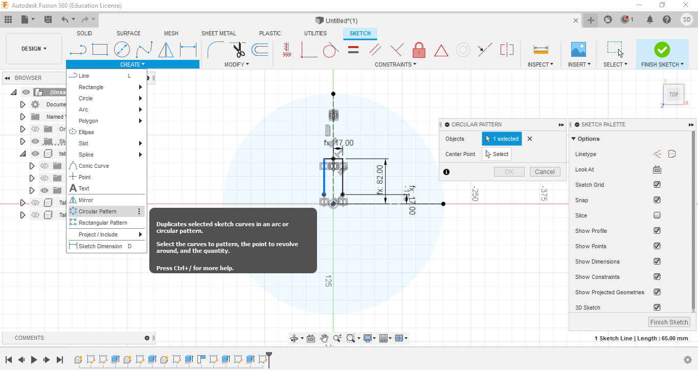
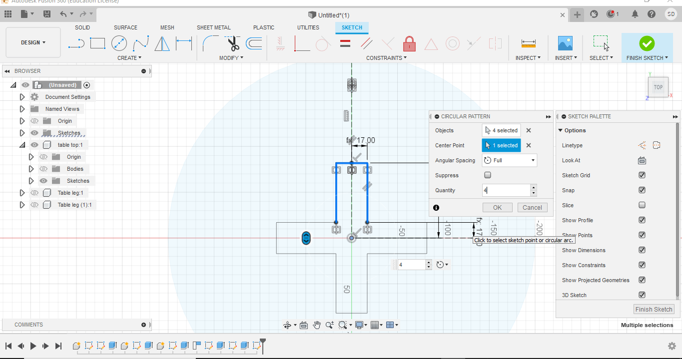
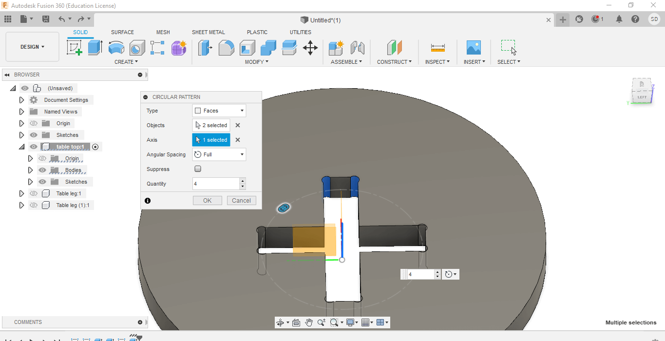
Similarly, I created press-fit joints on the table top to connect the legs with the table top. For the table top, I sketched on one side and used the circular pattern to make symmetrical joints on all 4 sides.
For the next step, I had to create some speacialty fillets known as dog bone fillets on all the internal corners. Dog-bone fillets are requires when manufacturing using CNC machine to because it is difficult to reach the corners using round cutting tools.
Also without dog bone fillets, I the pressfit joints will be very tight/difficult. To make the dog bone fillets, I followed the following steps;
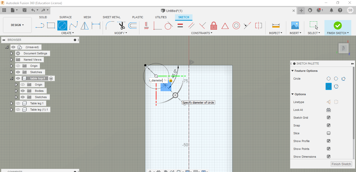
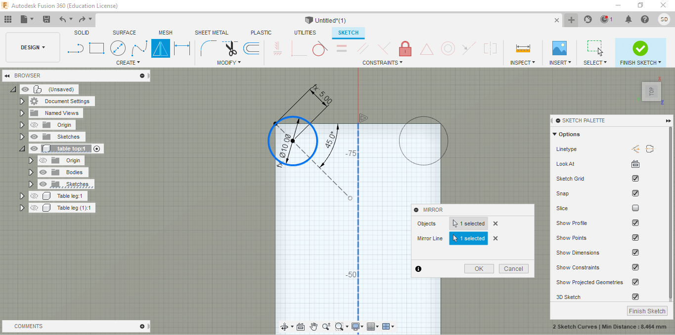
1. First create a construction line at 45 degree and create a circle with the center on the construction line. I gave the diameter of the circle as the parameter I defined for bit-diameter.
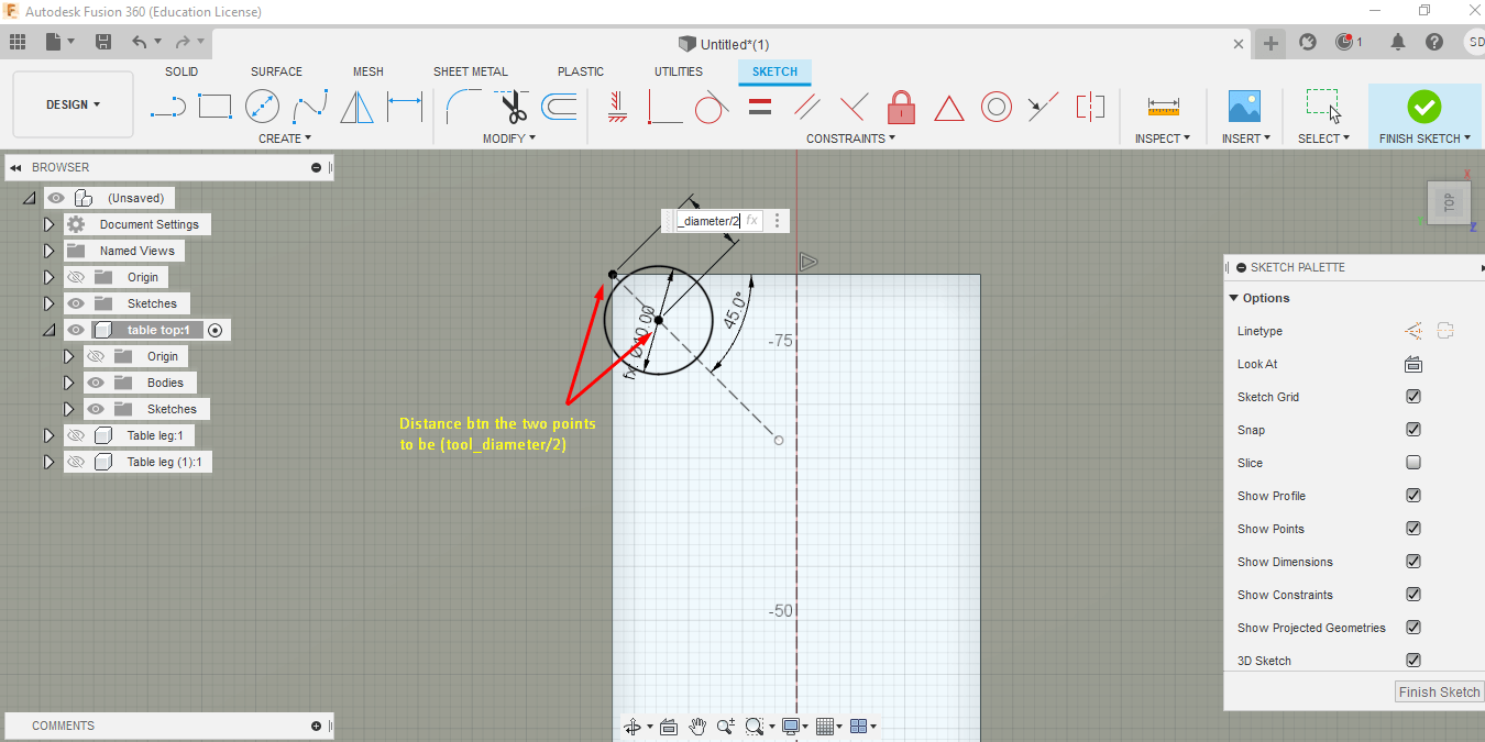
2. Next, I change the distance between the circle center and the edge point as half of the bit-diameter. Then, I used the mirror tool to create the same sketch on the other edge.
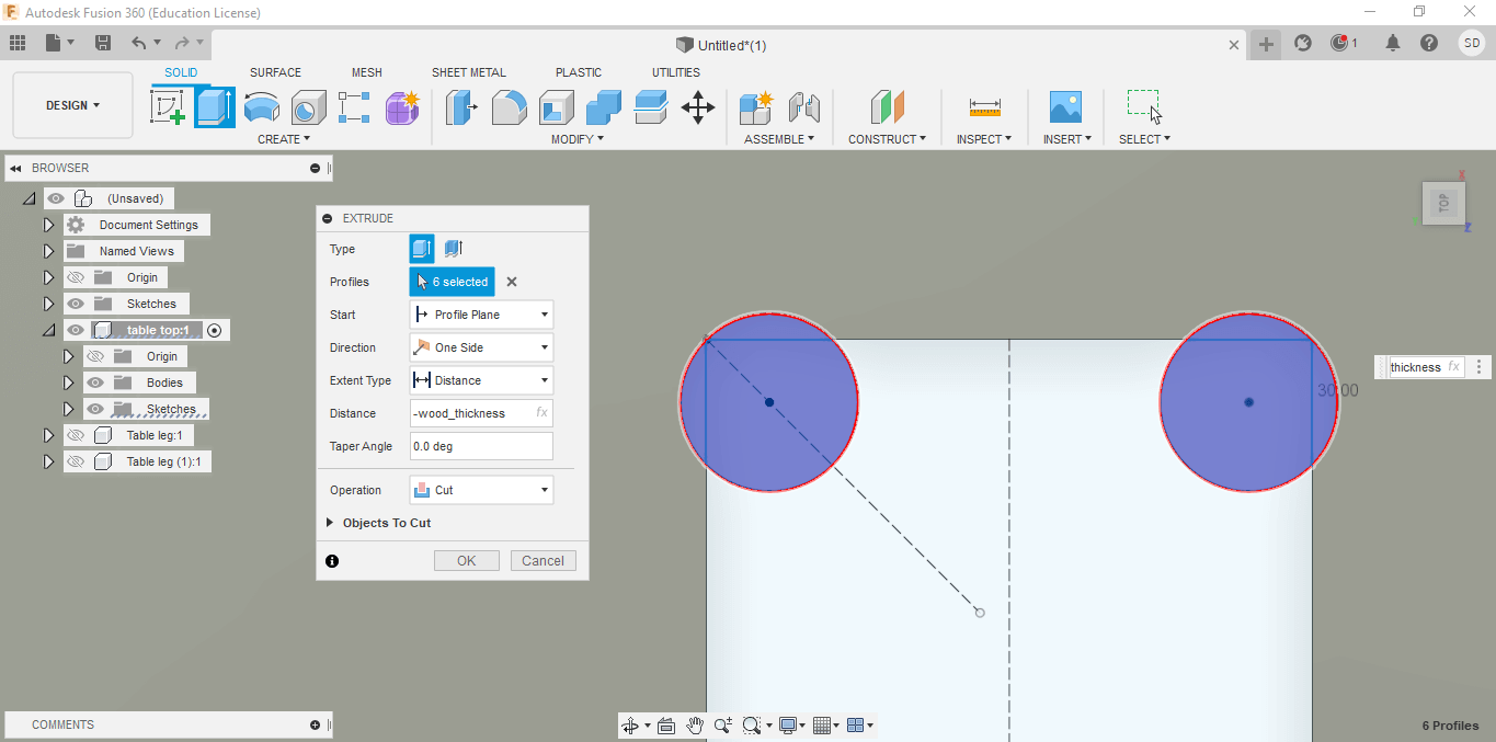
3. Lastly select the circle and extrude with negative ply-thickness parameter amount. Then, I used the circular pattern to create the dog bone fillet on all the other internal edges of the table top.
I made the dog bone fillets on all the internal corners. The final structure I made was shown below.
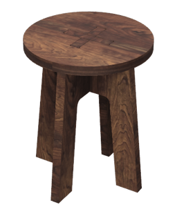
The model came out quite good and I learned many new features of the Fusion 360. However, I found the table to be too plain plus we were under lockdown so I couldn't visit the Labl.
Hence, I created another model. For the second table, I was inspired by the vintage tables which had beautiful carvings and shapes for table legs.
After surfing through the net for different designs, I finally decided on a table with butterfly wings for table legs.
I started with making a rough sketch of how I wanted my table to look like and followed the similar steps as those I followed for creating my first table model model.
One of the main challenges I faced was in creating the butterfly wing table legs. For creating the that I used the arc tool and I free hand drew the butterfly wings for table legs.
The first step was to define the parameters. Once the parameters were defined, I made a component for the table top and sketched a circular table top.
Next, I created a new component for the leg. I used the 3-point Arc tool to free-hand draw the butterfly wings. The final design came out as seen in the image below.
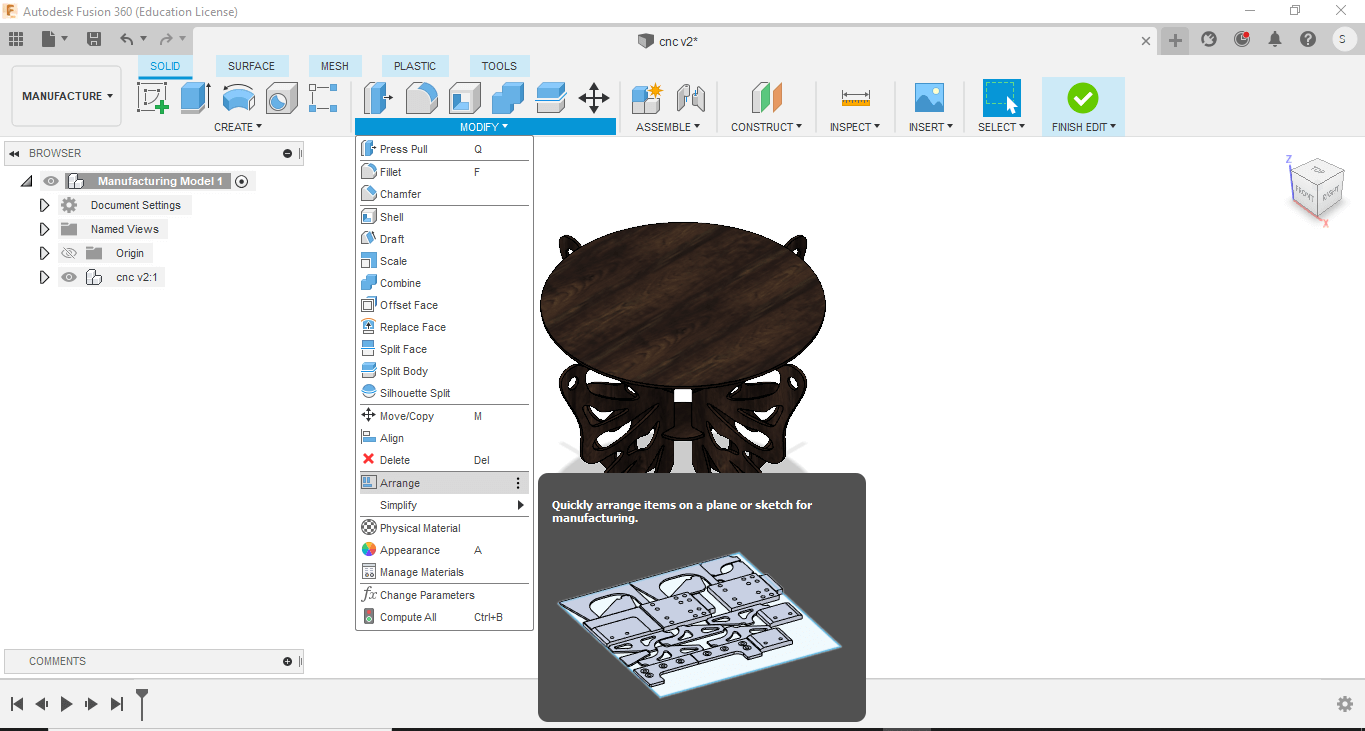
Once the design was completed, I used the arrage feature under Modify function to lay out the components check what dimensions of material would be required for cutting out all the individual parts.
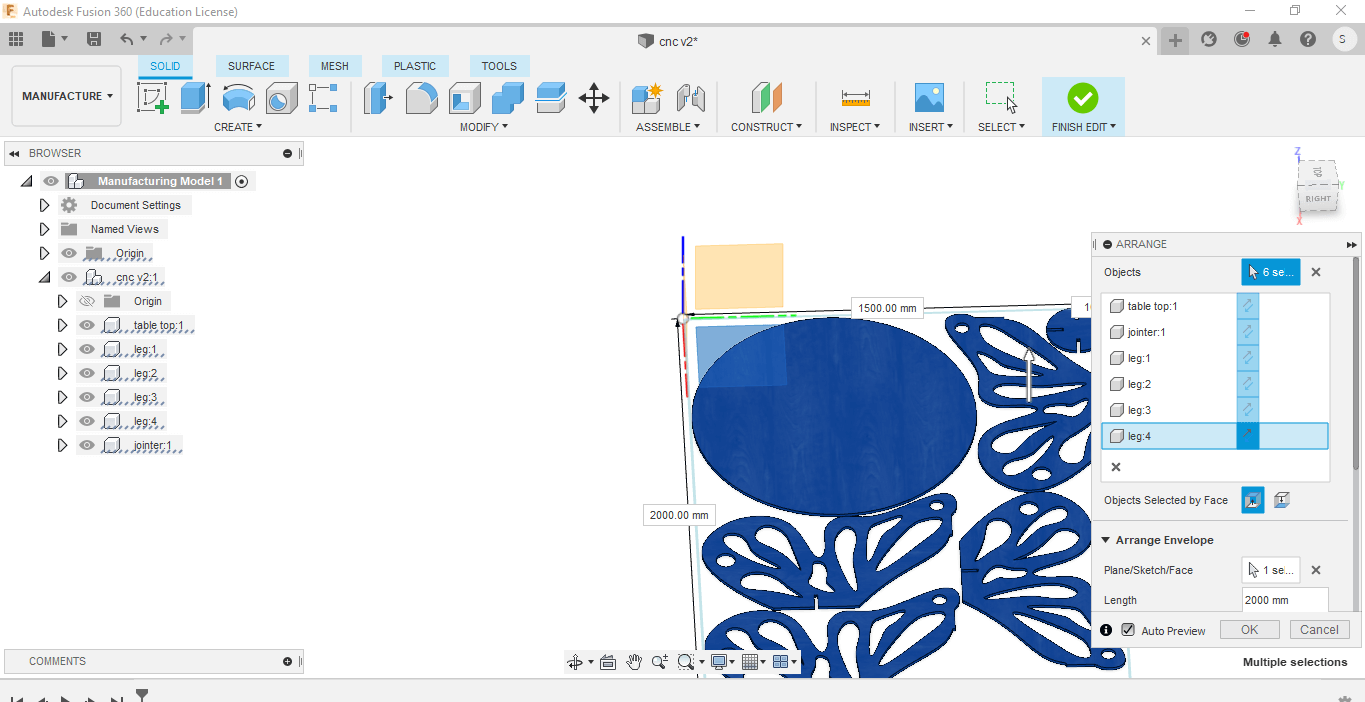
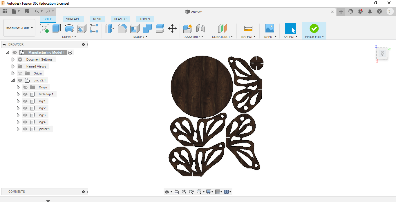
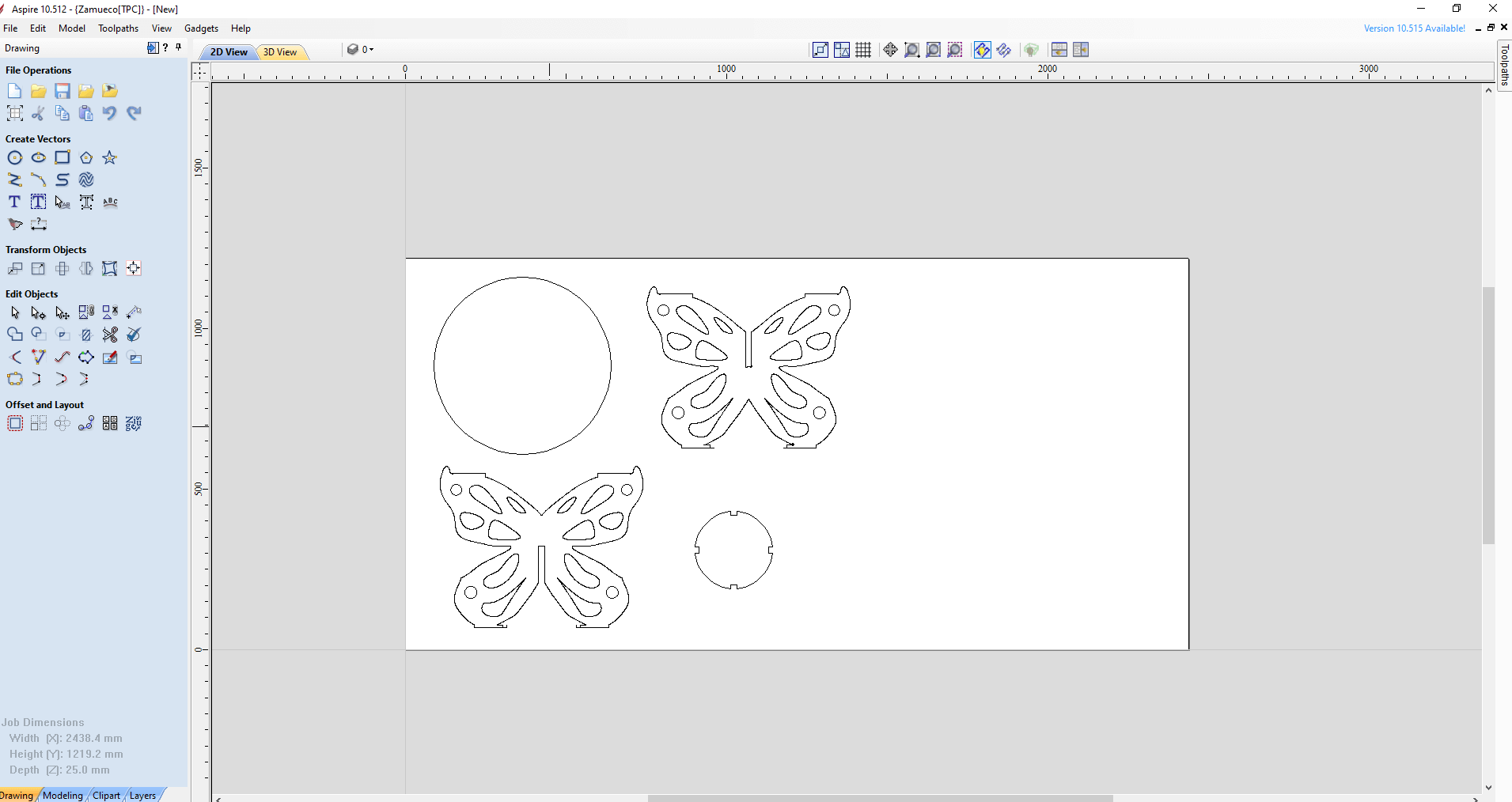
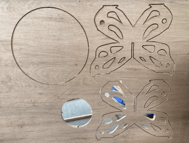
The following picture shows how the design components will look when laid out on a single plain for cutout.
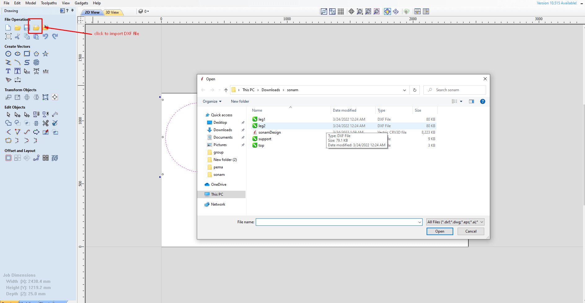
Once the designs were finalized, I saved the files in .dxf format.
CNC machine control and creating tool path\
The next step is to produce cutouts of my designs using CNC machine. The CNC machine at our lab is shopbot. We use the Aspire software to producing the machine readible files/toolpath for our designs. To do that, I imported and opened my .dxf design files in the aspire software.
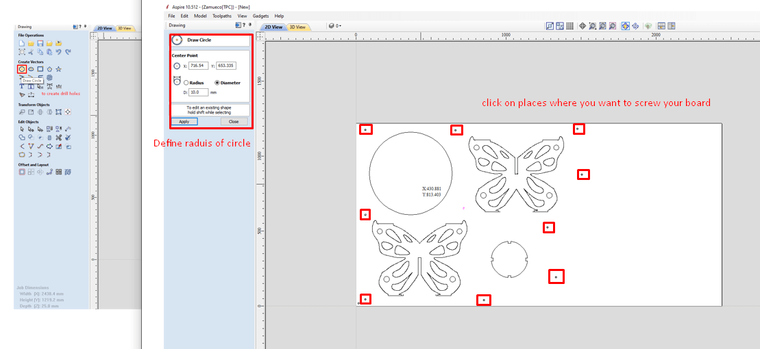
Next, I drew some circles on the locations where I wanted to screw my board.
For that, click on the draw circle tool → define the diameter for the circle → click on the points where I wanted to screws my board.
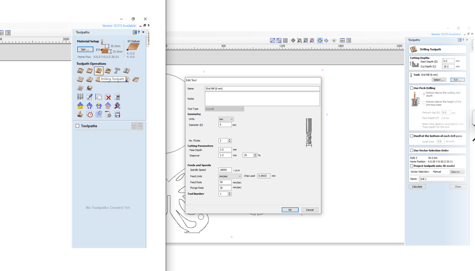
Once all the circles are drawn, I had to create the drill toolpath. To do that select all the circles and click on the drilling toolpath option. → define the diameter of the drill to be used and than click calculate.
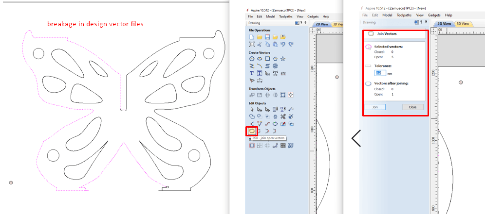
Next, I created the tool path for my design components. To do that select all the componentx. When selecting my components, I found that there were some breakages in the line. To solve this we use the Join tool to join the open vectors. To do that, select all the parts of the design component and click on join tool.
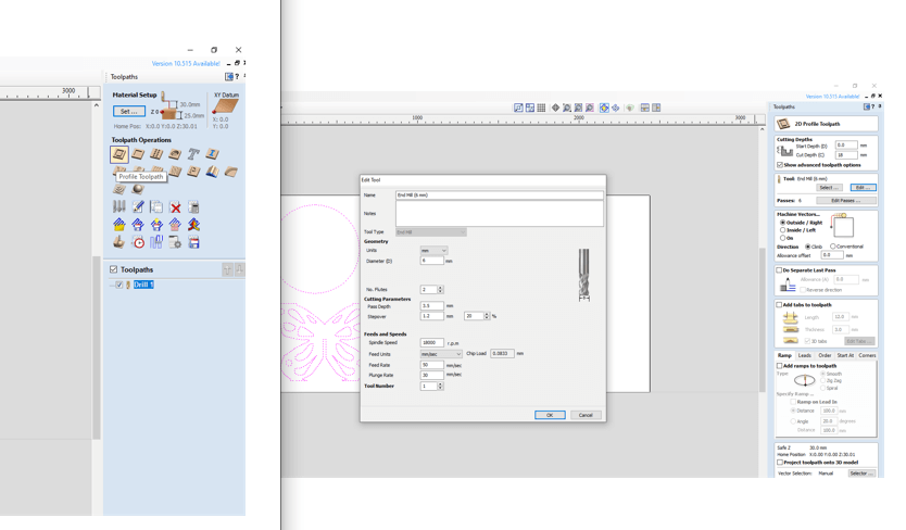
Once all the components were found to be complete without any breaks, I went ahead and created the profile toolpath. To do that Select the all the components and click on profile toolpath. I can specify the drill bit diameter, the cutting depth and weather I want the cut to be from inside or outside the design file. The specification I kept were as follows;
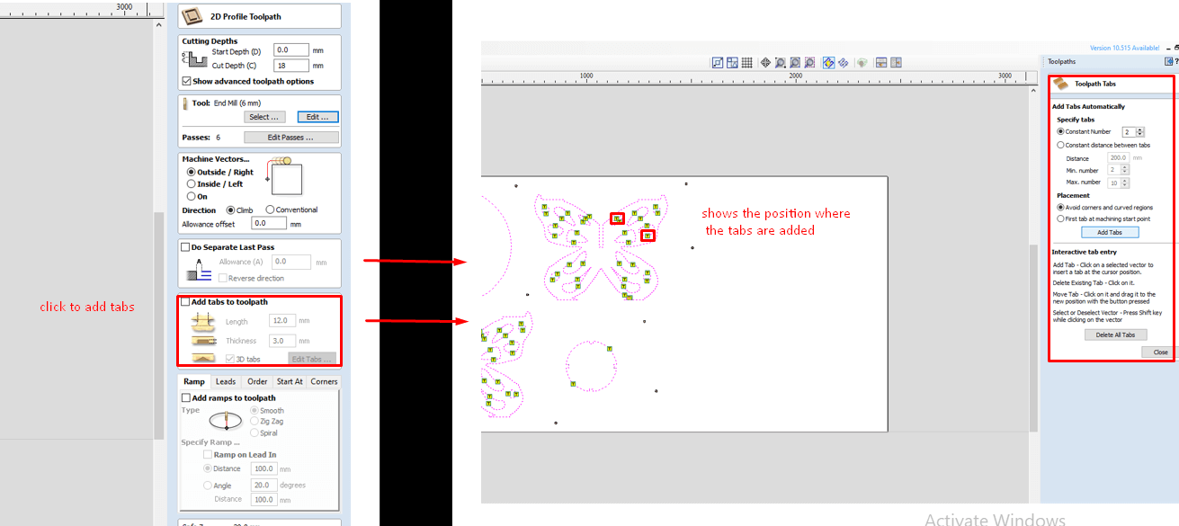
Since my designs had a lot of small cutouts, I added tabs to avoid the parts from jumping out when thet machine is operating. To add the tabs, click on add tabs function and then click on add tabs automatically. We can also add tabs manually by clicking on the part where we want the tabs to be.
Lastly, we save the drilling tool path and the profile tool path. To do that click on the Save toolpath icon. The tool path were as shown in image below.
Cutting in CNC
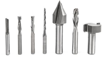
There are a couple of thingd that needs to be done before cutting the design on CNC. First we have to place the board on the bed of the shopbot and align it for drilling. Next we need to change the endmill to our requirement. In our lab we had a number of endmills available for the shopbot. Each endmill has different purpose. The endmills have cutting surfaces called flutes. .
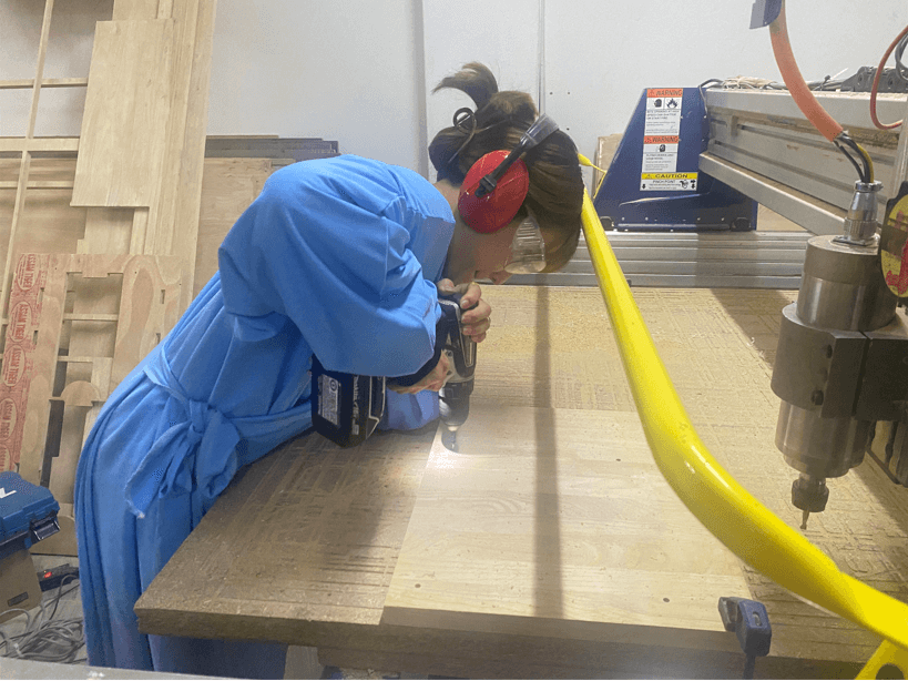
Next we import these toolpath to the machine console shopbot 3. First we import the drilling toolpath and start the machine. Once the machine has made circular holes in the designated places, stop the machine and screw the board to sacrifical layer on the to avoid the bed from moving.
I used a hand-driller to screw the board on all the circular patterns created by the CNC machine. The most commonly used endmill have 2-4 flutes.
For my design I used endmill with following specification;

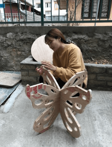
Next we load the profile toolpath. The design gets cut by the CNC machine. The Spindle Speed when cutting the design was 4000rpm Once the cutting the done, I stoped the machine. Unscrew the board and take out all the seperate components. In my case some of the parts were not compeletely cut through, so I had to use hexsaw to manually remove the parts.

Project Files