Week 10: OutPut Device
Output device of electronics are the electrical equipment that transform the electrical energy into another required energy for human being. Output device in electronics plays important role in the human world.
Even monitor screen, bulbs, fans and all are output device of the electricity. Input device controls Output device the way we want, but without output device, electronics will not have value.
Instruction:
Add an output device to a microcontroller board you've designed,
And program it to do something.
Group Assignment:
Measure the power consumption of an output device
- To Do:
- Learn about Output devices.
- Design controller for my output device (ESP32 board).
- Learn to program my controller.
- Program and control my output devices.
- Document on what I learn through this week
- Group Assignment.
Useful Links:
ESP32 Library for eagle here
ESP32 tutorial resources Here
Output Devices:
Output Devices are those that can convert electrical energy into any other useful energy for the consumption of the human being. Example, Bulb converts electrical energy into light energy, monitor screen converts energy into light and colors for human visualization, motor into rotational energy and so on. Light, Screen and rotational energies are used by human for various purposes.
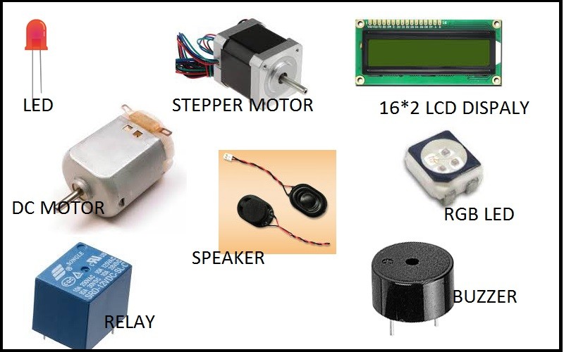
There are various types of output devices, some requires high power and some low power. Whether high power consumer or low power consumer can be controlled by controller in the way we want.
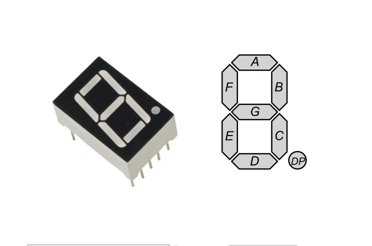
7 segment LED display is also one of the output device of the electronics, as it converts electrical energy into light energy and displays the number for the human visual.
One of my Output Devices for the final project is 7 Segment LED ot display count down number for human being before crossing the road.
So, taking the advantage of this week, I tried to fabricate 7segment led and try programing as an output device.
7Segment Fabrication:
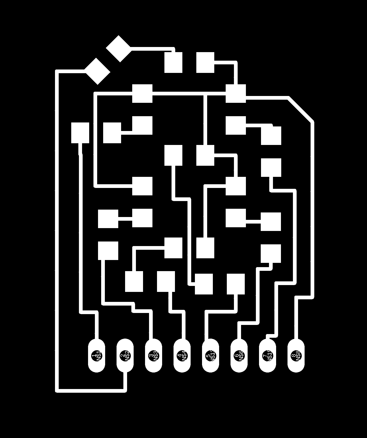
I did the designing of 7 segment in the eagle software. I just required 7 leds and and seven resistors as current limiting to the led. I haven't use any micro-controller for this circuit, as I just want this to be separate module, instead I kept connecter output so that i can connect from any output terminals.
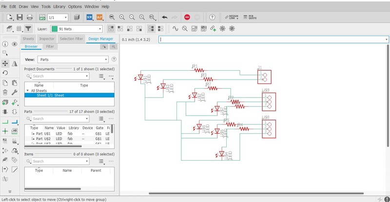
First, I added all the required components and made the circuit connections keeping the terminal connected to the pin headers.
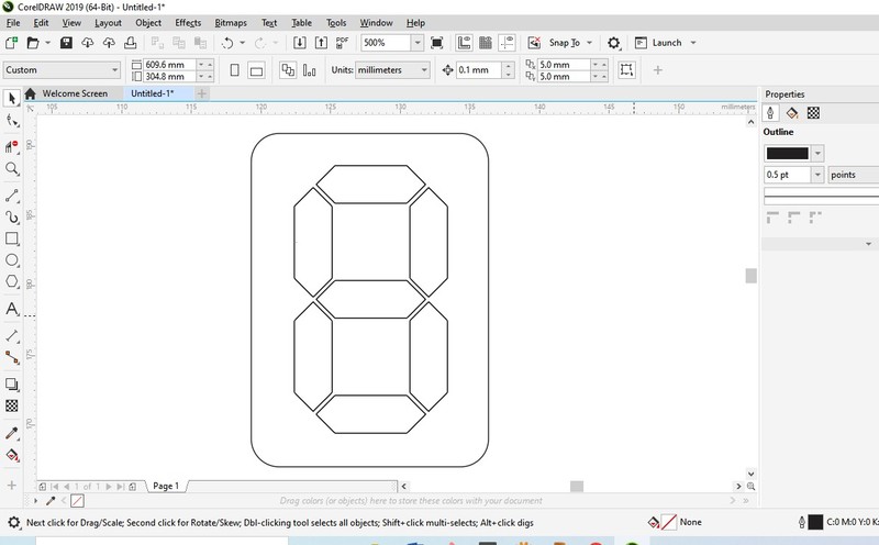
So, in order to make best shape of 7 Segment, I need to properly align the leds to one another. Inorder to get my alignment I measured the led size and using the 7 segment image, I made the dimension for the board. Saved it in dxf file format and need to open in fusion 360.
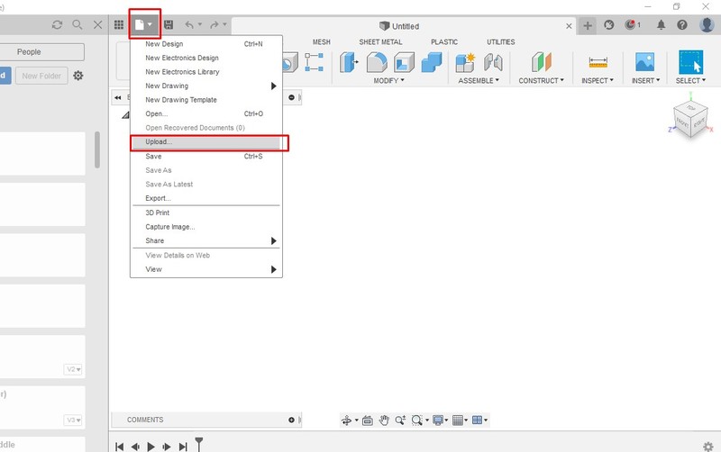
In fusion 360, we need to upload the dxf file to create the pcb outline.
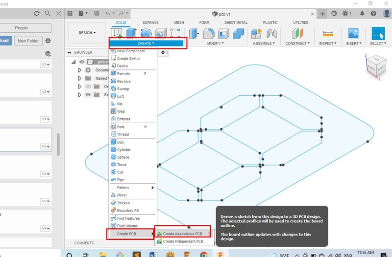
Now create the pcb as shown in above image.
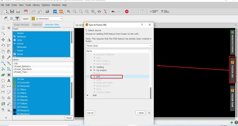
Now in eagle Board window import the design of pcb from fusion 360 as shown in above image.
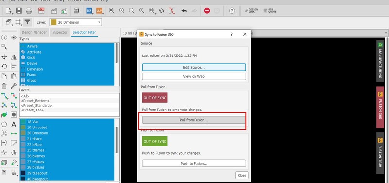
So, the above steps can bring the pcb created in the fusion 360 into the board design of eagle circuit. I inserted it as dimension layer.
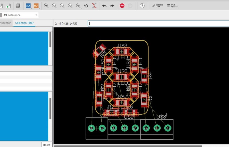
Once I get it into my board design, I pulled and placed the led in the required place to create it into 7 segment shape.
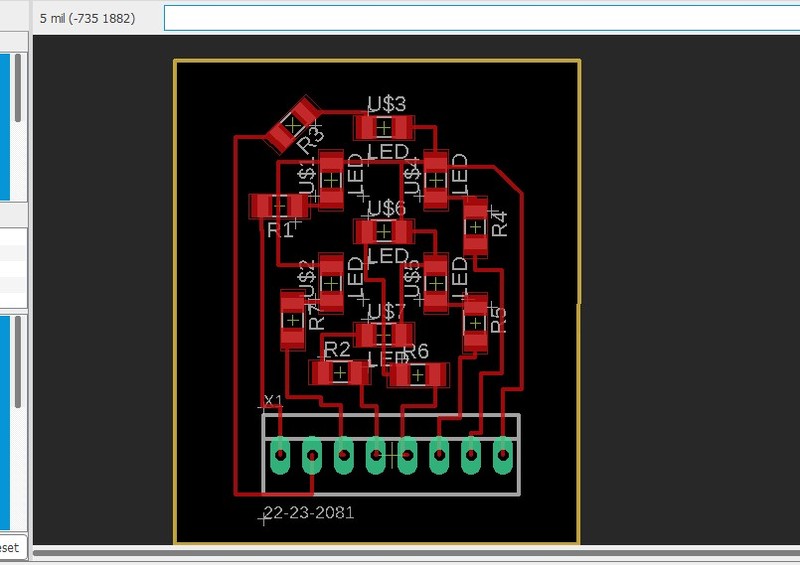
Once complete with the placement of leds in the position, removed all the dimension lines as it is not the real dimension I wanted to cut. So, created new dimensions for cutting and than exported in required format. You can Find my files at the end of the assignment.
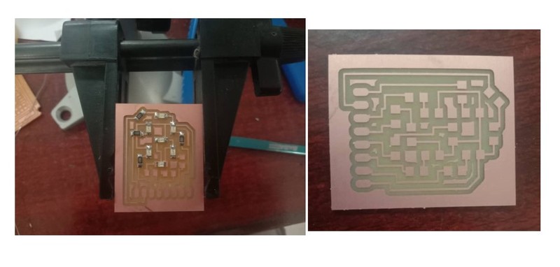
Milled the traces, cut and than place all the components required.
7 Segment working without the frame and screen to guide the light.
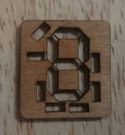
7 Segment requires its frame to control light and guide within it's segment rather than straying away. So, I used dxf file of eaarlier to cut in laser and made the segment guide. I also pick some translusant plastic to make the screen.
Display looks much better with screen and frame. We can see better segments with it.
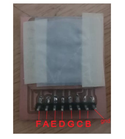
Output pins for my 7 segment led.
Controller Fabricating:
We also need to fabricate our own controller to control the output device for this week. As I require heavier controller for my final project, I tried to use esp32 micro-controller to be made for this week.
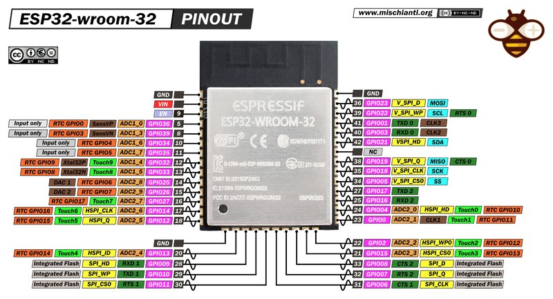
The basic requirement circuit to fabricate ESP32 WROOM as controller is given here. Find under ESP32 heading.

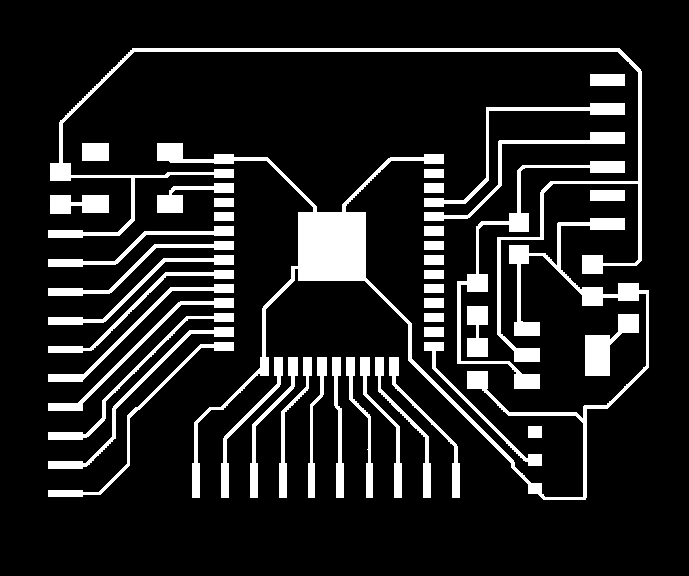
I designed circuit board as per minimum circuit required for esp32 and added some free pinouts so that I can program the pins later.
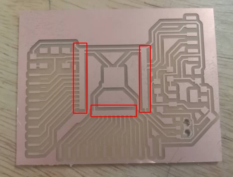
After the designing and exporting, I tried milling in the cnc milling machine and find out that pins of the esp32 were not printed. Iknew that I overlooked the view given in the mods.
Consultation with instructor found out that I need to change the pad size of the pins of the esp controller in the eagle library.
Doenload esp32 library of eagle from Here.
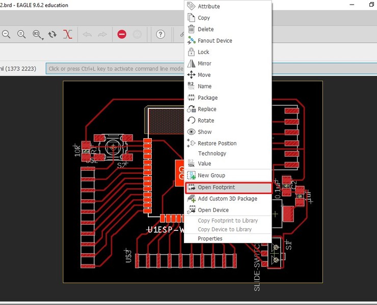
In order to change the pad size, Right click on the component and select Open Footprint to change it.
On the top, in the comment box, type change smd and enter to get drop down.
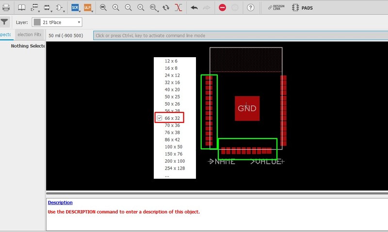
From the dropdown, select 66*32 usually it works for esp32 controller. After selecting, we need to select pins one by one to get changed.
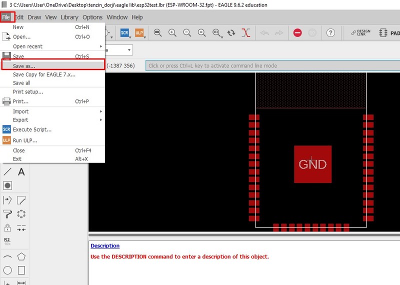
After the change, we need to save it as new library file.
Now open the component (ESP32) from new saved library and check if it worked.
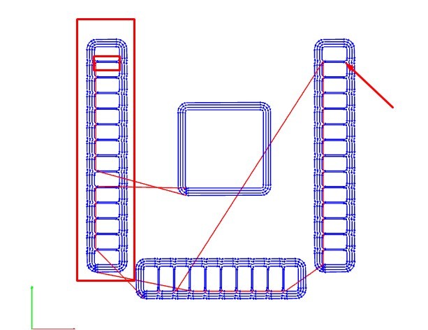
Before I use it in my design, I checked it in MIT MODS and looked working.
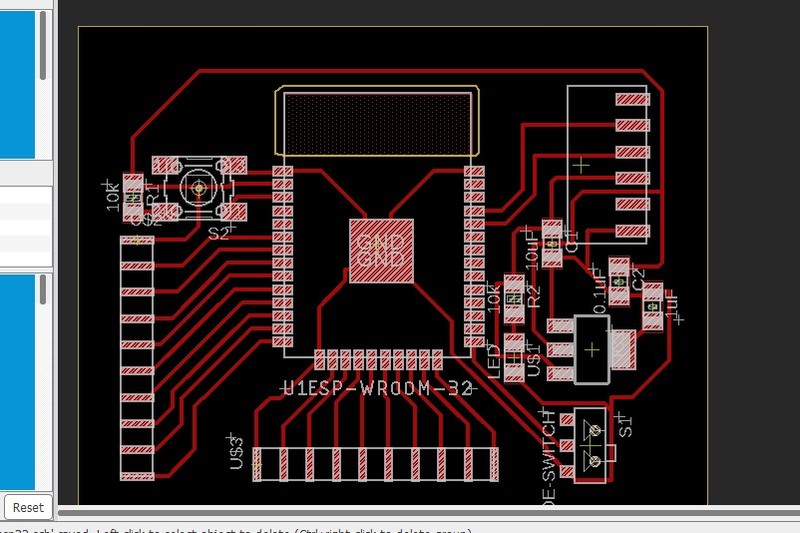
So, I changed the IC from new library that I have saved. Find my trace file and cut files at the end of the assignment.
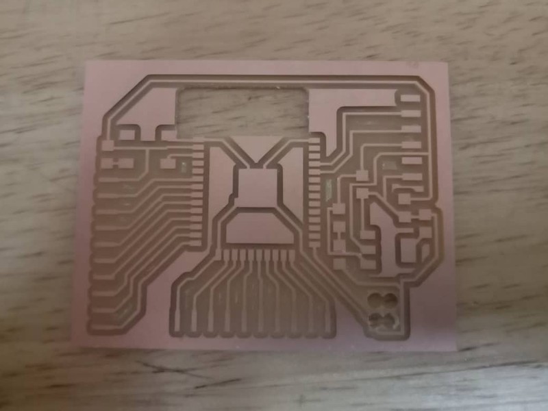
After editing, I did milling again and this time it came out well.
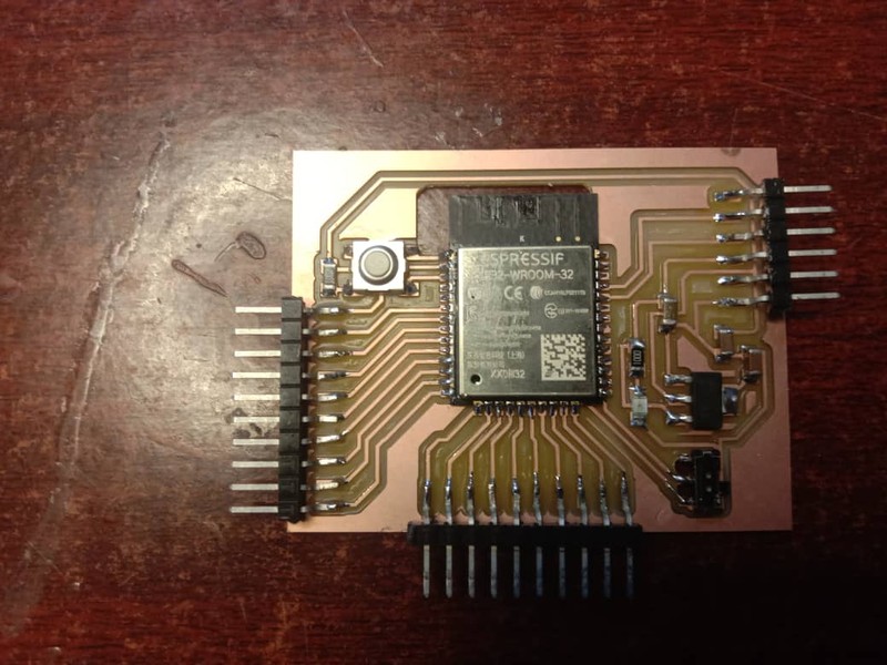
I soldered the required components as per my design and my board get ready for programming.
Programming ESP32:
Now it's time to program the controller board. We can use arduino IDE to program esp32, but we need to install the esp library like we did for attiny.
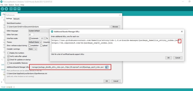
Under Files -> Preferences, we need to paste the https://dl.espressif.com/dl/package_esp32_index.json link as shown in above image. If you have another link already present in the text box, separate it using comma and keeping in new line.
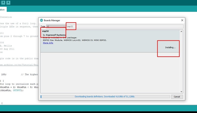
Once added, you can find the library available under Tools -> Board Manager. You can install it.
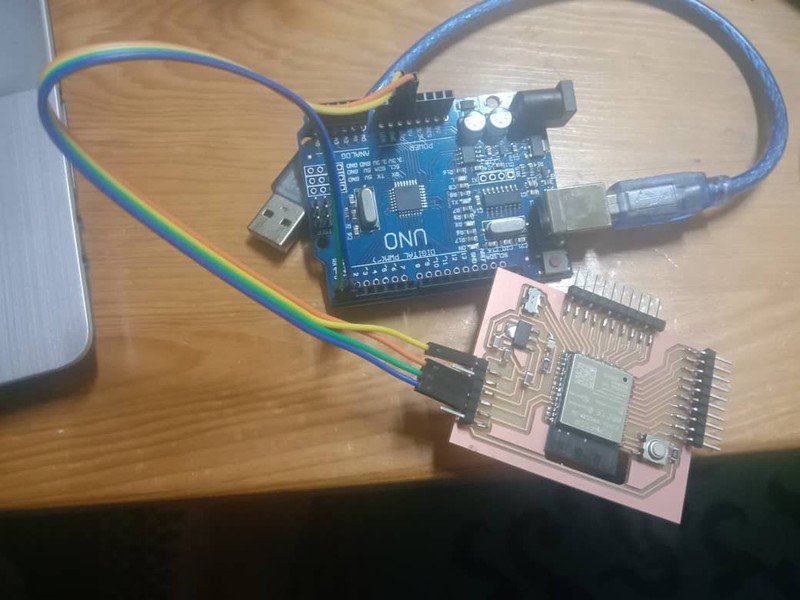
I used arduino as FTDI to program my ESP board. Unlike ATtiny, ESP32 doesn't require programmer, instead it uses FTDI programmer. So, we need to make arduino as FTDI by either
- Shotting the EN and GND of the arduino,
- Removing the IC of the arduino or
- Loading the blank program to the arduino.
I prefered loading program to the arduino to make it as FTDI.
	void setup(){
	pinMode(0,INPUT);
	pinMode(1,INPUT);
	}
	void loop(){
	}
This is simple arduino code that makes RX and TX pin of the arduino as output pin. Load this code to arduino that you are going to use as FTDI.
Now connect ESP board to power supply and connect RX and TX pin of arduino with RXD 0 and TXD 0 pins of ESP32 respectively.
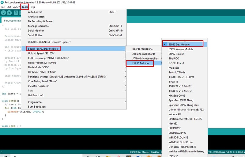
From the Tools -> Boards: -> ESP32 Arduino select ESP32 Dev Module to program our ESP32 WROOM 32 board.
Now keeping the Slide Switch in the programming mode i.e. connected position, to load program. You cannot select the Programmer, now, directly do upload as usual.
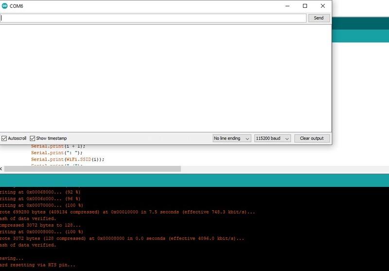
Once uploaded, there will not be any print on the Serial Monitor and it took me a whole lot of time tracing the mistake. But later found out that I need to put back Slide Switch to run position and press the Reset Button once.
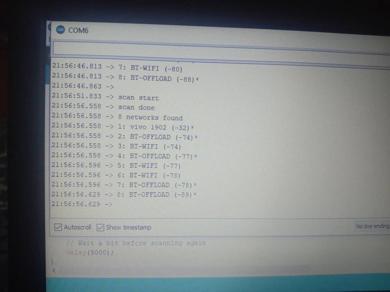
I was trying the example code of WiFiScan.
Programming 7 Segment on ESP board
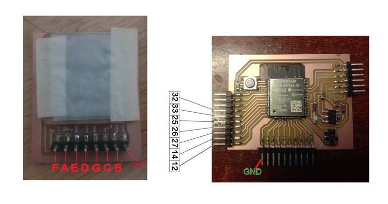
In order to program, first we need to know the pins that we are going to use. My pins required to connect and program are as in the image above.
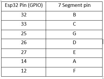
Pin Connection of my ESP32 board with 7 Segment LED.
	// array to store the pin no connected to A, B, C, D, E, F, G and DP
	// code from https://www.circuitgeeks.com/arduino-7-segment-display-tutorial/
	int seven_seg[] = {14, 32, 33, 26, 27, 12, 25};
	int num_array[10][7] = {{ 1, 1, 1, 1, 1, 1, 0 },  // 0
	                        { 0, 1, 1, 0, 0, 0, 0 },  // 1
	                        { 1, 1, 0, 1, 1, 0, 1 },  // 2
	                        { 1, 1, 1, 1, 0, 0, 1 },  // 3
	                        { 0, 1, 1, 0, 0, 1, 1 },  // 4
	                        { 1, 0, 1, 1, 0, 1, 1 },  // 5
	                        { 1, 0, 1, 1, 1, 1, 1 },  // 6
	                        { 1, 1, 1, 0, 0, 0, 0 },  // 7
	                        { 1, 1, 1, 1, 1, 1, 1 },  // 8
	                        { 1, 1, 1, 1, 0, 1, 1 }}; // 9
	// define a function
	void printNumber(int);
	void setup() {
	  for (int i = 0; i <= 8; i++) {
	    pinMode(seven_seg[i], OUTPUT);
	  }
	}
	void loop() {
	  // creating a for loop which counts from 0 to 9
	  for (int num = 0; num <=9; num++printNumber(num);
	    delay(1000);
	  }
	}
	// creating a function to print numbers
	void printNumber(int number) {
	  int pin;
	  for (int j = 0; j < 7; j++) {
	    pin = seven_seg[j];
	    digitalWrite(pin, num_array[number][j]);
	  }
	}
This is the simple 7 segment code that I used to program my esp32 to count from 0 - 9.
Reference
- ESP32 Library for eagle: https://github.com/lpodkalicki/eagle-libraries/blob/master/ics/esp32.lbr
- ESP32 tutorial resources: https://randomnerdtutorials.com/
- ESP32 Datasheet: https://www.alldatasheet.com/datasheet-pdf/pdf/1179101/ESPRESSIF/ESP-WROOM-32.html
- To modify pad size http://fabacademy.org/2021/labs/vigyanashram/students/pavan-mahadeokuchar/assignments/assignment11.html
- 7 Segment Programming https://www.circuitgeeks.com/arduino-7-segment-display-tutorial/
